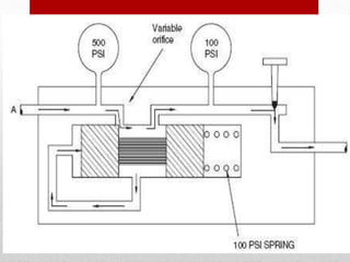
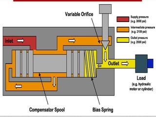
FLOW-CONTROL
VALVES
LECTURE 10
Introduction
• Flow-control valves, as the name
suggests, control the rate of flow of
a fluid through a hydraulic circuit.
Flow-control valves accurately limit
the fluid volume rate from fixed
displacement pump to or from
branch circuits.
• Flow-control valves have several functions, some of which are
listed below:
• 1. Regulate the speed of linear and rotary actuators : They
control the speed of piston that is dependent on the flow rate and
area of the piston:
• 2. Regulate the power available to the sub-circuits by
controlling the flow to them:
• 3. Proportionally divide or regulate the pump flow to various
branches of the circuit:
• It transfers the power developed by the main pump to different
sectors of the circuit to manage multiple tasks, if necessary.
Classification of
Flow-Control Valves
• Flow-control valves can be
classified as follows:
• 1. Non-pressure compensated.
• 2. Pressure compensated.
1. Non-pressure-compensated
• flow-control valves are used when the
system pressure is relatively constant and
motoring speeds are not too critical. The
operating principle behind these valves is
that the flow through an orifice remains
constant if the pressure drop across it
remains the same. In other words, the rate
of flow through an orifice depends on the
pressure drop across it.
Sometimes needle valves come
with an integrated check valve
for controlling the flow in one
direction only. The check valve
permits easy flow in the
opposite direction without any
restrictions.
2. Pressure-Compensated Valves
• Pressure-compensated flow-control
valves overcome the difficulty caused by
non-pressure-compensated valves by
changing the size of the orifice in relation
to the changes in the system pressure.
This is accomplished through a spring-
loaded compensator spool that reduces the
size of the orifice when pressure drop
increases.
• Once the valve is set, the pressure
compensator acts to keep the pressure
drop nearly constant. It works on a
kind of feedback mechanism from the
outlet pressure. This keeps the flow
through the orifice nearly constant.
A pressure-compensated flow-control
valve consists of a main spool and a
compensator spool. The adjustment
knob controls the main spool’s
position, which controls the orifice size
at the outlet..
• The upstream pressure is delivered to
the valve by the pilot line A.
Similarly, the downstream pressure is
ported to the right side of the
compensator spool through the pilot
line B. The compensator spring biases
the spool so that it tends toward the
fully open position.
• If the pressure drop across the valve
increases, that is, the upstream pressure
increases relative to the downstream
pressure, the compensator spool moves to
the right against the force of the spring.
This reduces the flow that in turn reduces
the pressure drop and tries to attain an
equilibrium position as far as the flow is
concerned.
•In the static condition, the
hydraulic forces hold the
compensator spool in balance,
but the bias spring forces it to
the far right, thus holding the
compensator orifice fully open.
•In the flow condition, any
pressure drop less than the bias
spring force does not affect the
fully open compensator orifice,
but any pressure drop greater
than the bias spring force
reduces the compensator
orifice.

hydralics lec10 (1).pptx

  • 1.
  • 2.
    Introduction • Flow-control valves,as the name suggests, control the rate of flow of a fluid through a hydraulic circuit. Flow-control valves accurately limit the fluid volume rate from fixed displacement pump to or from branch circuits.
  • 3.
    • Flow-control valveshave several functions, some of which are listed below: • 1. Regulate the speed of linear and rotary actuators : They control the speed of piston that is dependent on the flow rate and area of the piston: • 2. Regulate the power available to the sub-circuits by controlling the flow to them: • 3. Proportionally divide or regulate the pump flow to various branches of the circuit: • It transfers the power developed by the main pump to different sectors of the circuit to manage multiple tasks, if necessary.
  • 4.
    Classification of Flow-Control Valves •Flow-control valves can be classified as follows: • 1. Non-pressure compensated. • 2. Pressure compensated.
  • 5.
    1. Non-pressure-compensated • flow-controlvalves are used when the system pressure is relatively constant and motoring speeds are not too critical. The operating principle behind these valves is that the flow through an orifice remains constant if the pressure drop across it remains the same. In other words, the rate of flow through an orifice depends on the pressure drop across it.
  • 7.
    Sometimes needle valvescome with an integrated check valve for controlling the flow in one direction only. The check valve permits easy flow in the opposite direction without any restrictions.
  • 9.
    2. Pressure-Compensated Valves •Pressure-compensated flow-control valves overcome the difficulty caused by non-pressure-compensated valves by changing the size of the orifice in relation to the changes in the system pressure. This is accomplished through a spring- loaded compensator spool that reduces the size of the orifice when pressure drop increases.
  • 10.
    • Once thevalve is set, the pressure compensator acts to keep the pressure drop nearly constant. It works on a kind of feedback mechanism from the outlet pressure. This keeps the flow through the orifice nearly constant.
  • 13.
    A pressure-compensated flow-control valveconsists of a main spool and a compensator spool. The adjustment knob controls the main spool’s position, which controls the orifice size at the outlet..
  • 14.
    • The upstreampressure is delivered to the valve by the pilot line A. Similarly, the downstream pressure is ported to the right side of the compensator spool through the pilot line B. The compensator spring biases the spool so that it tends toward the fully open position.
  • 15.
    • If thepressure drop across the valve increases, that is, the upstream pressure increases relative to the downstream pressure, the compensator spool moves to the right against the force of the spring. This reduces the flow that in turn reduces the pressure drop and tries to attain an equilibrium position as far as the flow is concerned.
  • 16.
    •In the staticcondition, the hydraulic forces hold the compensator spool in balance, but the bias spring forces it to the far right, thus holding the compensator orifice fully open.
  • 17.
    •In the flowcondition, any pressure drop less than the bias spring force does not affect the fully open compensator orifice, but any pressure drop greater than the bias spring force reduces the compensator orifice.