Downloaded 204 times


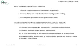
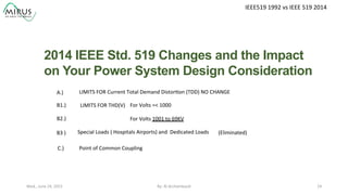
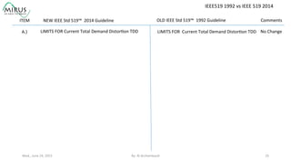
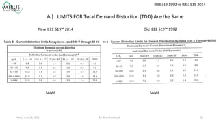
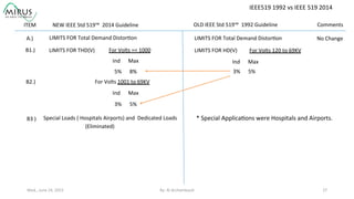
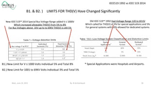
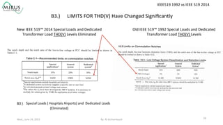
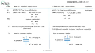

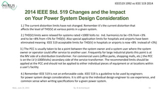


The presentation by Al Archambault discusses changes in the IEEE 519 standard from 1992 to 2014, highlighting their implications for power system design, particularly for engineers using variable speed drives. It emphasizes that while IEEE 519 serves as a guideline and is not enforceable, significant revisions were made, especially regarding Total Harmonic Distortion (THD) limits and the treatment of special loads like hospitals and airports. The new standard introduces updated THD limits and clarifications on points of common coupling, making it crucial for designers to adapt to these changes in their electrical systems.