This document is a thesis submitted by Stuart A. Deane to Trinity College Dublin in partial fulfillment of the requirements for a Masters in Bioengineering. The thesis describes the development of a bioengineered, decellularised xenograft for mitral valve replacement. Through a literature review, additional constructs were designed to standardize the surgical procedure and establish natural geometry. A decellularization protocol was assessed for its effects on mechanical properties and microstructure of porcine mitral valves. Uniaxial tensile testing showed the decellularization process did not significantly change the mechanical properties of the leaflets or chordae. Histological staining also showed no visible changes to microstructure or remaining nuclear material after decellular
![Stuart A. Deane Trinity College Dublin 2014
x
Figure 53 - typical true stress vs. true strain plot using video extensometry and Zwick force
data .............................................................................................................................................69
Figure 54 - Histogram showing lack of normality for chordae tensile test data.........................69
Figure 55 - Load Displacement Curve Illustrating the uncrimping of Collagen in relation to the
three regions...............................................................................................................................75
List of Tables
Table 1 - Reported Annular Dimensions .....................................................................................23
Table 2 - Showing comparison of various Inter-valley to Inter-peak sizes and an average........24
Table 3 - Measurements of Human and Porcine Hearts [62] .....................................................30
Table 4 - Decellularisation Processes..........................................................................................34
Table 5 - Results of uniaxial tensile tests carried out on Mitral Valve leaflet tissue displaying the
Modulus (MPa), UTS (MPa) and the % Strain at UTS..................................................................66
Table 6 - Results of Uniaxial Tensile test on both decellularised and fresh Mitral Chordae ......68](https://image.slidesharecdn.com/38e6f6e6-808d-47d7-b1bd-3ff471006261-150702142634-lva1-app6892/85/Stuart-Deane-Thesis-11-320.jpg)
![Stuart A. Deane Trinity College Dublin 2014
1
1 Introduction
In Britain approximately 1.87% of total cardiac surgeries are mitral valve replacements
(MVR). The total number of cardiac surgeries carried out in NHS hospitals in the year 2012 was
34,174 (639 MVR). Reports suggest, according to hospital discharges, that over 43,000 mitral
valve disorders were dealt with in The U.S, in 2003 [1]. If we were to extrapolate this based on
population increase alone this number rises to 48,562 mitral valve surgeries in the US in 2013.
According to Stanford school of medicine the national average is 43% replacement versus
repair [2]. This equates to almost 21,000 mitral replacements in the US every year. This is a
conservative estimate, not taking rising levels of obesity and an increasing elderly population
into account. Another report suggests that between 4.2-5.6 million adults in the U.S. had valve
disease in the year 2000 [3]. They discuss that 1 in 8 people older than 75 had a moderate to
severe valve disease and that of the 2.5% of the population affected as much as 1.8% had a
mitral valve disease.
When a mitral valve is defective there are two means of surgical intervention; repair
or replacement. At the moment the majority of surgeries carried out are repairs as this
represents a safer and more durable solution. Replacement is only selected when repair is not
amenable due to extensive damage. There are several options available when replacing a
valve; mechanical, bioprosthetic and allograft. The mechanical valves are associated with
much longer lifetimes and are therefore the preferred option when treating patients under
the age of 65 or who have a longer projected lifetime. There are two major drawbacks to
mechanical valves which are the necessity of long-term anticoagulation therapy and the forfeit
of natural hemodynamics. The bioprosthetic options are generally made of a fixed animal
tissue which is constructed on a plastic frame. These valves, in the mitral position, do not offer
the expected lifetimes of the mechanical valves for patients under 65 but do not require the
anticoagulation therapy [4]. For this reason they are the valve of choice for older patients or
those to whom anticoagulation therapy is not applicable.
The use of allografts in the clinical setting is very limited. A homograft when implanted
triggers an immunogenic response to donor tissue which requires anti-immunogenic drug
treatment. To combat this, techniques such as cryopreservation were employed to minimise
the immunogenic response. Formerly the majority of implants were cryopreserved until more
recent trials showed the lack of viability post-processing which lead to rapid calcification and](https://image.slidesharecdn.com/38e6f6e6-808d-47d7-b1bd-3ff471006261-150702142634-lva1-app6892/85/Stuart-Deane-Thesis-12-320.jpg)
![Stuart A. Deane Trinity College Dublin 2014
3
2 Literature Review
2.1 Anatomy and Physiology
2.1.1 The Cardiovascular system
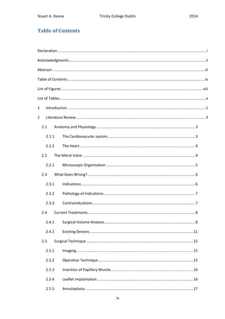
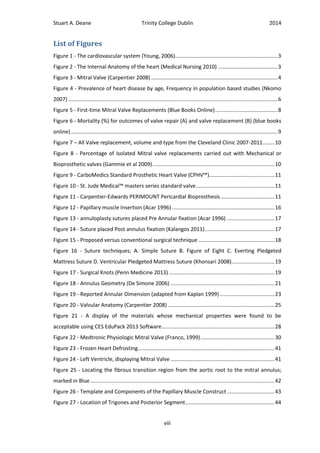
The heart is part of the
cardiovascular system in the body shown
in Figure 1 [5]. The cardiovascular system
is made up of the heart and the many
blood vessels running throughout the
body supplying nutrients and oxygen and
removing waste. It is essentially the
pump which maintains the flow of blood
through the system. The heart is split into
two sides the right receives blood from
the body and pumps it
to the lungs to
exchange carbon
dioxide for oxygen,
and the left receives
the oxygenated blood
from the lungs and
pumps it to the body.
The pumping pressure
is created by the
contraction and
relaxation of the
muscle wall.
Figure 1 - The cardiovascular system (Young, 2006)
Figure 2 - The Internal Anatomy of the heart (Medical Nursing 2010)](https://image.slidesharecdn.com/38e6f6e6-808d-47d7-b1bd-3ff471006261-150702142634-lva1-app6892/85/Stuart-Deane-Thesis-14-320.jpg)
![Stuart A. Deane Trinity College Dublin 2014
4
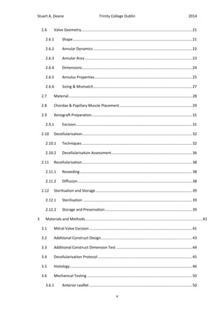
2.1.2 The Heart
The heart is approximately the size of a fist and is located in the thoracic cavity (chest
cavity) and has a mass of 250-350 (g) depending on the individual. Both sides of the heart are
split into two chambers; the atrium which receives the blood and the ventricle which pumps
the blood back out as shown in Figure 2 [6]. The ventricles take up most of the volume of the
heart, and the left in particular. As the muscle here is required to do more work it is much
thicker. In order to maintain blood flow in one direction the outlet of each chamber is
controlled by a valve. These valves work on the difference in pressure created by the relaxing
and tensing of the ventricular and atrial wall.
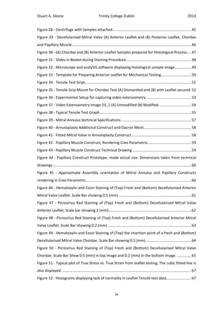
2.2 The Mitral Valve
The Mitral valve (also known as the
Bicuspid or the left Atrioventricular valve) is
located between the left atrium and ventricle.
This valve is under the most pressure, as it is
subject to the pressure caused by the contraction
of the left ventricle, and its failure will mean the
loss of nutrients and oxygen to the body. The
valve is made up of the annulus, the leaflets, the
chordae tendinae and the papillary muscles. The
Annulus is the area which surrounds the leaflets
and represents the edge of the valve as it is
positioned in the heart in the atrio-ventricular
junction (between the two chambers). There are
two leaflets (the anterior and posterior) and these are flaps of endocardium reinforced by a
connective tissue core that are attached to the inside of the annulus shown in Figure 3 [7].
The papillary muscles are embedded in the ventricular wall. The chordae are chords
of collagen which stretch from the valves to the papillary muscles. When the ventricle
contracts the pressure in the chamber causes the flaps to close and the chordae prevent the
valve from prolapsing (everting) into the atrium and thus prevent regurgitation. The papillary
muscles contract along with the ventricle wall tightening the chords [8]. Collectively, the
chordae and the papillary muscles are known as the sub-valvular apparatus. An indication of
Figure 3 - Mitral Valve (Carpentier 2008)](https://image.slidesharecdn.com/38e6f6e6-808d-47d7-b1bd-3ff471006261-150702142634-lva1-app6892/85/Stuart-Deane-Thesis-15-320.jpg)
![Stuart A. Deane Trinity College Dublin 2014
5
the size of the valve is given in the study by Acar of 82 homografts; the height of the anterior
leaflet was 25 ± 3 (mm). It was also noted that the distance from the apex of the anterior
papillary muscle to the annulus was 21 ±3 (mm). The distance from the annulus to the apex of
the posterior papillary muscle was 26 ± 4 (mm) [9].
2.2.1 Microscopic Organisation
The Structure of the valve leaflet can be split into several stratified layers. Each layer
begins at the basal edge and extends a distance into the valve providing different mechanical
properties. The main layers are the Spongiosa, Fibrosa and the Atrialis [10, 11]. The fibrosa is
made up of circumferentially orientated collagen fibrils to provide tensile stiffness, it is located
on the ventricular aspect of the valve [10]. The fibrosa is the thickest layer in the porcine
mitral valve and extends from the annulus into the valve where the collagen fibres propagate
into the chordae [11]. The Atrialis is found on the atrial aspect of the valve and extends from
the annulus approximately two thirds of the length of the valve. This layer consists
predominantly of radially orientated elastic fibres and also smooth muscle cells [11]. This layer
permits movement by tolerating extension and recoil [10]. The spongiosa is a layer of loose
connective tissue extending from the annulus to the free edge, where it makes up most of the
thickness [11]. It is comprised of proteoglycans interspersed with collagen and elastin. The
spongiosa provides compressibility, integrity and acts as an interface between the orthogonal
Atrialis and fibrosa [10]. The exterior of the valve is covered in continuous endocardial
endothelial layer which extends from the endocardial endothelial layers of the ventricle and
atrium. Cardiac muscle extends into the base of the valve which may lead to limited
vasculature. It is noted in Hinton et al (2011) that there is a particular balance of stiffness and
flexibility provided by the complex ECM which is essential for proper valve function [10].
There are five cell types found in the valves; valvular interstitial cells (VIC),
endocardial, cardiac muscle, endothelial and smooth muscle cells [11]. The most predominant
cell type is the VIC which is found in all layers. The distinct structure of the valve in
homeostasis is dependent on gene expression from the VIC that encodes fibrillar collagens,
proteoglycans and elastin [10] and thus it is highly likely that VIC have an important role in
valve remodelling. It is interesting to note that VIC have shown contractile properties which
may suggest that they maintain more than a passive support and could alter to aid
withstanding hemodynamic forces [11].](https://image.slidesharecdn.com/38e6f6e6-808d-47d7-b1bd-3ff471006261-150702142634-lva1-app6892/85/Stuart-Deane-Thesis-16-320.jpg)
![Stuart A. Deane Trinity College Dublin 2014
6
2.3 What Goes Wrong?
2.3.1 Indications
Total Mitral Valve replacement is indicative only when much less complex valve repair
reconstruction techniques are not amenable, due to it being considered a much more severe
surgical procedure. Replacement occurs when there is extensive damage to the valve leaflets
and valve apparatus [9]. The patient population changes from region to region as more
developed healthcare systems have increased ability for prophylaxis of disease reducing
rheumatic disease but in conjunction with that an increased life expectancy raises the
incidence of degenerative conditions [3, 12]. This is the opposite in developing countries
where rheumatic valve disease still presents a major health problem and affects a much
younger population. In a study by Chikwe et al the Aetiology of valve failure was shown for
patients recommended for both mitral repairs and replacements. Showing a significantly
higher level of rheumatic (3.5-27.4%) and endorcarditis (1.8-13.7%) recommended for
replacement, but still a higher percentage for Degenerative disorders (40%) [13]. A study by
Nkomo et al shows that incidence of valve disease is significantly associated with age in the
U.S. as shown in Figure 4.
Damage is traditionally caused by conditions such as severe rheumatic degeneration,
leaflet calcification, bacterial endocarditis (causing extensive tissue loss) and with the presence
Figure 4 - Prevalence of heart disease by age, Frequency in population based
studies (Nkomo 2007)](https://image.slidesharecdn.com/38e6f6e6-808d-47d7-b1bd-3ff471006261-150702142634-lva1-app6892/85/Stuart-Deane-Thesis-17-320.jpg)
![Stuart A. Deane Trinity College Dublin 2014
7
of complex lesions. Repair is avoided in these situations because of asymmetrical stenosis,
calcareous incrustations and valvular abscess formation [14] warranting valve replacement. In
one study by Acar et al the indications for operation were as follows: rheumatic mitral stenosis
(n = 26), acute infective endocarditis (n = 14), systemic lupus endocarditis (n = 2), and
marasmic endocarditis (n = 1).
2.3.2 Pathology of Indications
The pathologies of the various indicative diseases are important to consider as they
may change how a device performs when implanted. With Mitral Stenosis caused by
rheumatic carditis the valves are progressively thickened, scarred and calcified. These effects
cause fusion of the commissures and the chordae tendinae eventually reducing the effective
orifice area. This decrease will lead to a higher atrial pressure and can initiate atrial
enlargement. The pathophysiology for mitral regurgitation, caused by rheumatic heart disease
and acute infective endocarditis is similar. The left ventricle overloads as it must pump both
the stroke volume and the amount of blood regurgitated. This can cause ventricular dilation. It
has also been noted that the annular tissue can be friable (easily crumbled) due to these
conditions which can affect suturing. The Pathology associated with degenerative disease is
similar as mitral regurgitation is associated with LV enlargement and mitral stenosis is
associated with larger LA diameters [3].
2.3.3 Contraindications
According to Acar et al notable contraindications for traditional homograft are
unfavourable anatomy of the recipient papillary muscles due to the complex nature of the
surgical procedure, patients who are receiving a reoperation after a prosthetic valve (due to
issues with sizing) and young patients who are still growing (due to strong immune reactions)
[15]. It is hoped that by addressing each of these issues these contraindications can be
overcome.](https://image.slidesharecdn.com/38e6f6e6-808d-47d7-b1bd-3ff471006261-150702142634-lva1-app6892/85/Stuart-Deane-Thesis-18-320.jpg)
![Stuart A. Deane Trinity College Dublin 2014
8
2.4 Current Treatments
2.4.1 Surgical Volume Analysis
According to the online database resource provided by the Society for Cardiothoracic
Surgery in Great Britain & Ireland [16] the total number of cardiac surgeries carried out in the
year 2012 was 34,174 for all NHS hospitals. Of these procedures 2,118 were Isolated first time
mitral, either repair or replacement. The number of MV replacements was 638 (Figure 5), of
which 356 were isolated and 282 of which involved coronary artery bypass grafting (CABG).
Equating to approximately 1.87% of total Cardiac surgeries. Outcomes from these surgeries, in
terms of mortality, are shown adjacent to those for repair in Figure 6. The mortality for
replacement is marginally over twice that of repair (4.23-1.99%).
Figure 5 - First-time Mitral Valve Replacements (Blue Books Online)](https://image.slidesharecdn.com/38e6f6e6-808d-47d7-b1bd-3ff471006261-150702142634-lva1-app6892/85/Stuart-Deane-Thesis-19-320.jpg)
![Stuart A. Deane Trinity College Dublin 2014
9
In the United States (U.S.) a study carried out by Gammie et al over an 8 year period
(2000-2007) recorded 58,370 primary isolated MV surgeries (This excludes 127,261 patients
with concomitant CABG, aortic and other valve issues) from a total of 910 participating
hospitals. Of these 24,404 were replacements (41%) [17]. They concluded that the mortality
rate for replacement was consistently higher than for repair (3.8% vs. 1.4%), similar to that
found in Britain. These figures confirm that repair is presently a more desirable approach to
valve replacement.
In their study Gammie et al also recorded the type of valve replacement taking place
either mechanical or bioprosthetic; the results can be seen in Figure 8. The results indicate a
clear trend in the increasing popularity of the Bioprosthetic over the traditional mechanical
replacement valve. Their conclusions establish that improved reoperative mortality rates and
longer lifetimes without degeneration are the reasons behind this.
For more recent surgical trends we can look at data from the Cleveland Clinic, Ohio
US, which is the US leader in overall valve surgery and mitral valve surgery volume per
institution. In 2011 they carried out 1,286 primary mitral valve operations of which 416 (32%)
were replacements [18]. Their data, from 2007-2011, shows a dramatic shift towards the use
of bioprosthetics over mechanical valve replacements; as can be seen in Figure 7.
(A) (B)
Figure 6 - Mortality (%) for outcomes of valve repair (A) and valve replacement (B) (blue books online)](https://image.slidesharecdn.com/38e6f6e6-808d-47d7-b1bd-3ff471006261-150702142634-lva1-app6892/85/Stuart-Deane-Thesis-20-320.jpg)
![Stuart A. Deane Trinity College Dublin 2014
10
This shift in valve replacement type is attributed to advancement in fixation
technology in the tissue engineered bioprosthesis. In the past they were considered to
degenerate too quickly, particularly in younger patients, or patients with significant life
expectancy however recent studies have shown significant improvements in possible implant
lifetimes, with a low rate of valve related events at 18 years for patients over 65 [19]. The
Mechanical replacement is also less desirable due to the necessary long term anticoagulation
therapy.
Figure 8 - Percentage of Isolated Mitral valve replacements carried out with Mechanical or Bioprosthetic valves
(Gammie et al 2009).
Figure 7 – All Valve replacement, volume and type from the Cleveland Clinic 2007-2011](https://image.slidesharecdn.com/38e6f6e6-808d-47d7-b1bd-3ff471006261-150702142634-lva1-app6892/85/Stuart-Deane-Thesis-21-320.jpg)
![Stuart A. Deane Trinity College Dublin 2014
12
fixated using a glutaraldehyde solution. The annulus is made up of a flexible silicon rubber
covered in a knitted PTFE mesh.
Although these more developed valves have been shown to improve lifetime and
reduce calcification they still do not compare to the longevity of the mechanical valves. A
study carried out by Hammermeister et al (2000) compared the outcome of 181 mitral valve
replacements to compare the 15 year results of mechanical versus bioprosthetic valves [20].
Their results (although using older generation valves) revealed that in the mitral position
mechanical valves had a lower primary failure than bioprosthetics but that these result were
offset by the higher bleeding rate associated with anticoagulation therapy. A more recent
study shows the 25 year results of the PERIMOUNT placed in the mitral position [4]. They have
concluded that the expected valve “durability” was 11.4, 16.6 and 19.4 years for age groups
<60, 60-70 and >70 respectively.
Homograft/Xenograft
The first clinical procedure using a tissue engineered heart valve was carried out by
Dohmen et al in 2000 [21]. They describe the use of a cryopreserved decellularised pulmonary
allograft replacing the right ventricular outflow during a ROSS operation. The valve was
cultured for four weeks in autologous vascular endothelial cells (AVEC) in order to assure
recellularisation and thus no valvular calcification. The single operation, at one year, was
successful. They conclude by noting that the ideal Extra-Cellular Matrix (ECM) for tissue
engineered heart valves may be porcine due to their relative abundance and cost. More
recently Ali et al (2004) published the results of a much larger study involving the implanting
of 104 mitral homografts and eight-year follow-up data [22]. The valves used were
cryopreserved and they noted that after this process the valves did not retain any
recellularisation viability. Similarly to the bioprosthetics the durability appears to be related to
the recipient’s age, they noted a higher rate of cardiac events in patients below 40. They
stated that a majority of the early valve failures were due to patient mismatch and the
technique could be refined by intraoperative sizing.
A commercially available decellularised porcine heart valve, the SYNERGRAFT™
(CRYOLIFE Inc.) was introduced as an alternative to conventional bioprosthetics. A consequent
study by Simon et al (2003) exposed rapid early failure in paediatric patients [23]. They
concluded that the ECM provoked a strong inflammatory response causing structural failure](https://image.slidesharecdn.com/38e6f6e6-808d-47d7-b1bd-3ff471006261-150702142634-lva1-app6892/85/Stuart-Deane-Thesis-23-320.jpg)
![Stuart A. Deane Trinity College Dublin 2014
13
and rapid degeneration. They hypothesised that this response may be due to pre-implant
calcific deposits and incomplete decellularisation. Implantation of the SYNERGRAFT™ was
subsequently stopped. Again more recently Cebotari et al (2011) have compared the use of
fresh decellularised allografts for pulmonary valve replacement to glutaraldehyde-fixed bovine
and cryopreserved homografts [24]. Their findings suggest that the decellularised valves
showed better viability in that they provided “adaptive growth”, although the patient did have
to be called into hospital with short notice (3 weeks) for implantation. They also mention that
in their ovine tests in the decellularised allograft there was little invasion by inflammatory
cells.
An influential article by Rieder et al (2005) investigated the immune response of
decellularised porcine tissue in comparison to human tissue [25]. They established that the
decellularised (processed) xenograft ECM were more pro-inflammatory than the human tissue
which had not been decellularised and that the decellularised human tissue performed best.
These findings suggest that in the development of a decellularised ECM scaffold developed
from a native valve structure Homografts rather than Xenografts represent a better chance of
success. Initially this appears to negate the study of future Xenograft valve scaffold but
Hopkins et al (2005) remarks that guidance document 1994 put forward by the FDA in relation
prosthetic valves and ISO 5840:1996 suggest that before such a valve can be considered for
human trial it must first be replicated in a large animal trial [26]. The results by Rieder et al
now appear to recommend that such an animal model would need to be carried out using a
valve from the same species in order to properly simulate the in vivo immunological conditions
and that these findings and protocols would then be transferred to a human model. Therefore
this suggests that the first step in developing a successful decellularised homograft mitral
valve is to develop a successful decellularised xenograft mitral valve. It is important to note
that these results were based on decellularisation and assessment protocols available in 2005.
It is expected that by using more recent techniques a more thoroughly decellularised
xenograft ECM can be achieved.
The major advantage of using Xenograft material over homograft material is the
unrestricted material quantity. In response to the issue that a suitable homograft may not be
available a number of “homograft banks” have been set up to harvest, sterilise and store
homografts for future use. A number of these can be found, for example the national heart
centre Singapore, the European Homograft Bank in Brussels and a small clinical unit based at](https://image.slidesharecdn.com/38e6f6e6-808d-47d7-b1bd-3ff471006261-150702142634-lva1-app6892/85/Stuart-Deane-Thesis-24-320.jpg)
![Stuart A. Deane Trinity College Dublin 2014
14
the John Radcliffe Hospital in Britain. A recent report by Walter et al (2012) called the
practicality of these institutions into question by detailing a limited availability of suitable
donors and a wide variety in decontamination and thawing techniques meaning graft quality is
difficult to compare [27].
Another possible technology which may be utilised in the future is the creation of
autologous tissue-engineered heart valves (TEHVS) using biodegradable synthetic materials
[28].A promising study which utilises in vivo reseeding appears the most positive [29]. Much
more research and further in vitro and clinical trials will be necessary to establish the
advisability of this technology.
As has been shown there are several benefits of the viable Xenograft over traditional
mechanical prosthesis, bioprosthesis and homograft. As well as use when repair is not
appropriate the avoidance of long-term anticoagulation therapy can result in a much more
satisfying patient experience as the risk of a thromboembolic event is lower [30, 31]. It is
hypothesised that another benefit of the decellularised xenograft over a traditional fixated
bioprosthetic would be that due to cellular ingrowth the body would sustain the valve over
longer periods of time increasing durability due to viability [24]. Another benefit over
traditional prosthesis is the preservation of both natural ventricular geometry and
hemodynamics which reduces stress on the heart. As the study by Vetter et al shows the
leaflet motion was comparable with recordings obtained from natural mitral valves [32]. It is
thought that due to the Mitral valves intricate sub valvular apparatus that retaining the
natural structure will better mimic the regular bileaflet motion.](https://image.slidesharecdn.com/38e6f6e6-808d-47d7-b1bd-3ff471006261-150702142634-lva1-app6892/85/Stuart-Deane-Thesis-25-320.jpg)
![Stuart A. Deane Trinity College Dublin 2014
15
2.5 Surgical Technique
2.5.1 Imaging
Preoperative trans-esophageal echocardiography is performed to carry out a detailed
examination of the mitral valve and sub-valvular apparatus and to guide surgical strategy [9].
One reason for this is to examine the functionality and extent of damage to assess the
necessity of valve replacement [14]. In traditional surgery the native valve must be measured
in order to match to the xenograft. Important dimensions to take note of are the valve annular
diameter, height of the anterior leaflet, chordal and papillary muscle length and shape
(morphology) of the chords and papillary muscles [14]. These dimensions could be used to
choose a replacement valve. With the use of an off-the-shelf product this sizing can be
achieved intra-operatively and more accurately. It is suggested that Intra-operative trans-
esophageal echocardiography is repeated to compare pre and post-replacement valvular
function [14]. In one study the morphologic characteristics of the papillary muscles and the
distribution of the chordae were noted for each homograft and recorded on a specifically
designed identification card due to their individuality in each patient [9].
As the morphology of the papillary muscle and chordae can be quite individual to each
patient the study by Acar found it necessary to subdivide the features into four groups based
on the existence of a division in the muscle and its location with respect to the commissure:
“Type I, Simple single muscle. Type II, divided muscle in the sagittal plane forming an individual
head supporting chordae of the posterior leaflet. Type III, divided muscle in a coronal plane
forming an individual head supporting the commissural area of the leaflet. Type IV, divided
muscle with multiple heads originating at different levels on the ventricular wall from the apex
to the base” [9]. The number of anterior papillary muscles in each classification is as follows:
type I, n = 47; type II, n = 12; type III, n = 14; and type IV, n = 9, and for the posterior papillary
muscles: type I, n = 43; type II, n = 22; type III, n = 7; and type IV, n = 10. This indicates more
type I and type II than III and IV. It is also noted that Acar found type IV to be unsuitable for
implantation and these were discarded.
2.5.2 Operative Technique
Valve replacement must be carried out using “open” heart surgery. Firstly the patient
is given a general anaesthetic. The surgeon will open the chest wall and cut through the
breastbone to expose the heart; in a small number of cases a small incision between the ribs is
sufficient. Once the surgeon gains access to the heart a heart and lung bypass machine is](https://image.slidesharecdn.com/38e6f6e6-808d-47d7-b1bd-3ff471006261-150702142634-lva1-app6892/85/Stuart-Deane-Thesis-26-320.jpg)
![Stuart A. Deane Trinity College Dublin 2014
16
attached to move blood away from the heart and take over the pumping action and function
of the lungs. To open the heart a small incision is made in the left atrium. Most people spend
4-7 days in hospital following surgery.
2.5.3 Insertion of Papillary Muscle
The first step of attaching the new valve is inserting
the papillary muscles. Suturing of the papillary muscles end
to end would result in a poor join and thus the development
of an entirely new technique was necessary. The Donor
muscle is placed between the host papillary muscle (which
has been left intact during excision of the valve) and the
ventricular wall. In the study by Kalangos the host papillary
muscle and the ventricular wall are sutured in a “sandwich
fashion” around the donor papillary muscles using 4/0
pledgeted teflon sutures [14]. The technique used by Acar et
al is very similar. They first placed a number of mattress
sutures at the base of the graft muscle, then a number of
interrupted sutures along the margins of the graft and finally
at the apex as shown in Figure 12 [9]. It is important that the sutures do not interfere with the
origin of the chordae to prevent causing erosion.
2.5.4 Leaflet implantation
Before leaflet implantation sutures for mitral annuloplasty were placed around the
perimeter of the native annulus. The leaflet tissue was then sutured using a 4/0 braided
polyester suture around the circumference [9, 14, 33]. Both Acar and Kalangos use a
continuous suture for this. Acar details the order in which each annular segment is attached;
(1) posteromedial commissure, (2) anterior leaflet, (3) anterolateral commissure, and (4)
posterior leaflet. It is also noted that particular care is taken in the placement of the
positioning of the commissures [9].
Figure 12 - Papillary muscle Insertion
(Acar 1996)](https://image.slidesharecdn.com/38e6f6e6-808d-47d7-b1bd-3ff471006261-150702142634-lva1-app6892/85/Stuart-Deane-Thesis-27-320.jpg)
![Stuart A. Deane Trinity College Dublin 2014
17
2.5.5 Annuloplasty
Annuloplasty fixation
Much of the basis of this
device lies in refining the surgical
procedure to make quicker and more
reproducible surgical techniques than
are currently available. The need for
this refinement is outlined as it
demonstrates a major issue which
halts progress in establishing valvular
replacement via xenograft as a
superior treatment [15]. With this in
mind this research suggests that that
the incorporation of an annuloplasty
ring onto the graft at pre-surgery
could significantly reduce time spent
choosing and fitting during surgery.
The use of an annuloplasty
has many benefits all of which are
outlined by Acar [33]. His reasons for the
addition are as follows “the semirigid
structure” of the annuloplasty will
absorb the majority of the stress
experienced by the continuous valvular
suture line generated by ventricular
contraction; this could be attributed to
the dilation which often accompanies
the indications for replacement. As well
as this the ring allows a greater surface of leaflet coaptation, thereby lowering the tension on
the subvalvular apparatus by conforming the native annulus to the natural geometry of the
xenograft [9, 33].
Figure 14 - Suture placed Post annulus fixation (Kalangos
2011)
Figure 13 - annuloplasty sutures placed Pre Annular fixation
(Acar 1996)](https://image.slidesharecdn.com/38e6f6e6-808d-47d7-b1bd-3ff471006261-150702142634-lva1-app6892/85/Stuart-Deane-Thesis-28-320.jpg)
![Stuart A. Deane Trinity College Dublin 2014
18
Current techniques to fixate the valve leaflets do not vary significantly from author to
author. In most cases the fixation of the mitral homograft annulus to the native annulus is
accomplished by suturing using a continuous suture. In two recent surgical guides a 4/0
polypropylene monofilament is used [14, 33] to accomplish this. It is interesting to note that a
pre-dated paper also involving Christophe Acar advises the use of continuous 5-0 Prolene
polypropylene suture [9]. It is unclear why the surgeon changes from 5/0 to 4/0 suture but it
does equate both techniques and the change occurs during a period when Acar is performing
multiple surgeries [22], therefore we can presume the change is based on experience. Also in
one of these studies the sutures to fixate the annuloplasty are placed along the perimeter of
the host annulus prior to leaflet fixation, Figure 13, whereas the newer guide has these
stitches placed after annulo-fixation, Figure 14. Both Studies use 2/0 braided polyester sutures
to secure the annuloplasty and both used an interrupted stitch. An additional
recommendation is the use of 2/0 Tevdek (Braided polyester) [34]. The results recorded in one
study conducted by Acar using this technique demonstrate encouraging results from 104
patients with freedom any cardiac event 76% at 7 years and patients free from cardiac death
and all death as 90.6% and 82% after 8 years [22]. The important detail to take from this is
that it is conventional that both the donor annulus and annuloplasty are sutured to the host
annulus as shown in Figure 15 A. It is suggested that the donor annulus be secured to the
Annuloplasty pre-operatively, which in turn could be secured to the host annulus trans-
operatively thereby reducing surgery by one step and refining the surgical procedure by
standardising this step. This difference in technique is shown, Figure 15 B. The major
difference is both the integration and sealing of the homograft is largely dependent on the
annuloplasty ring. This extra functionality must be considered in annuloplasty ring choice as a
custom design may be required.
Figure 15 - Proposed versus conventional surgical technique](https://image.slidesharecdn.com/38e6f6e6-808d-47d7-b1bd-3ff471006261-150702142634-lva1-app6892/85/Stuart-Deane-Thesis-29-320.jpg)
![Stuart A. Deane Trinity College Dublin 2014
19
Suturing Technique
Surgical suturing
techniques to secure the
annuloplasty are shown in
Figure 16 [34]. The
suturing techniques
suggested for mitral valve
surgery are dependent on
the condition of the
tissue. It is noted that the
annular tissue is often
edematous (abnormal
accumulation of fluid,
swelling) and friable
(crumbly) and in this case
it is more beneficial to use horizontal mattress with soft felt pledgets as shown [34].
The Sutures can be completed
using a simple box knot or a surgeons knot
as shown in Figure 17 [35]. The sutures
should be placed 3-4 (mm) apart along the
annulus. The suggestion is made that the
leaflet tissue be kept moist with
intermittent rinsing with room temperature
physiologic saline solution as the heat from
the operating room lights will dry out and
permanently damage the tissue. It is also
noted that consideration be given to the
left circumflex coronary artery which
courses through the atrioventricular groove
first outside the posterior mitral annulus.
The coronary sinus also transverses around
the annulus and is likely to be encountered
Figure 16 - Suture techniques; A. Simple Suture B. Figure of Eight C. Everting
Pledgeted Mattress Suture D. Ventricular Pledgeted Mattress Suture (Khonsari
2008)
Figure 17 - Surgical Knots (Penn Medicine 2013)](https://image.slidesharecdn.com/38e6f6e6-808d-47d7-b1bd-3ff471006261-150702142634-lva1-app6892/85/Stuart-Deane-Thesis-30-320.jpg)
![Stuart A. Deane Trinity College Dublin 2014
20
in the region of the posteromedial commissure. The artery to the atrioventricular node also
may run parallel to the annulus just above the posteromedial commissure.
The size of the annuloplasty ring is chosen based on the size of the donor valve, in
both cases corresponding to the surface area of the anterior mitral leaflet [14] and in one case
outlining the use of an obturator [9], therefore sizing inter-operatively is not an issue.
Testing
A question arises as to whether a test, to determine the mechanical stress which the
fixation sutures of the homograft with pre-implanted annuloplasty could withstand in
comparison to the current surgical technique, should be performed. At the time of writing the
author was not aware of any appropriate established tests in this area as the technique has
been refined over many years and was originally adopted from mitral valve repair [36]. There
are a number of studies which deal with the use of computational models to estimate forces
experienced [37]. It is important to note that homograft failure due to dehiscence of the
leaflet tissue is not common in the failure of homograft devices. The one case of Dehiscence
experienced in Acars study of 104 patients was attributed to an underestimated replacement
valve due to a dilated left ventricle [22] which caused the chordae to put more tensile stress
on the leaflet. In another study the case described was attributed to the omission of an
annuloplasty ring [38]. It is therefore not thought necessary to test for mechanical properties
of the junction.](https://image.slidesharecdn.com/38e6f6e6-808d-47d7-b1bd-3ff471006261-150702142634-lva1-app6892/85/Stuart-Deane-Thesis-31-320.jpg)
![Stuart A. Deane Trinity College Dublin 2014
21
2.6 Valve Geometry
The next consideration is the choice of annuloplasty ring as there is a range to choose
from. The traditional role of the annuloplasty is restoration of natural geometry. As mentioned
previously the ring must take on extra functionality in the proposed technique by taking the
role of integrating and sealing the homograft as the transferred annulus and native annulus
will no longer be directly sutured. The two major characteristics to take into account therefore
are shape (change in shape) and mechanical properties (material).
2.6.1 Shape
The shape of the mitral valve is complex and
changes with the stage of the cardiac cycle. A plan
view of the mitral valve will show a D shaped profile
[39]. In three dimensions the annulus is well known
to approximate a saddle shape [40]. A study to
record the regional annular distortion of the mitral
annulus using 3-dimensional echocardiography with
respect to mitral regurgitation, measured using 3-
dimensional colour Doppler obtained the
reconstruction shown, Figure 18 [41]. Their
acquisition was based on 2˚ increments until 90 heart
cycles were recorded. This reconstruction shows the
“saddle” shape associated with the mitral annulus.
More importantly their conclusion on the choice of annuloplasty states that it should be based
on individual case of the valvular apparatus, suggesting that intra-operative sizing would be
appropriate.
A study which used both numerical simulation and experimental data investigated the
mitral valve stress experienced [42]. The numerical simulation compared flat to “markedly”
saddle shaped phantom annulus and discovered that minimum peak leaflet stress occurred at
15-25% annular height to commissural height ratio. The experimental data used 3D
echocardiography to image sheep, baboon and human valve geometry and found that each
had a ratio of 10-15%. Their conclusion was that the shape confers a mechanical advantage by
adding curvature. A study using 3D echocardiographic analysis in humans measures a mean
Figure 18 - Annulus Geometry (De Simone
2006)](https://image.slidesharecdn.com/38e6f6e6-808d-47d7-b1bd-3ff471006261-150702142634-lva1-app6892/85/Stuart-Deane-Thesis-32-320.jpg)
![Stuart A. Deane Trinity College Dublin 2014
22
value of annular height (AH) to intercommisural width (inter-valley) ratio of 22.7±6.9% [43].
The measurements taken in another study show a change in height from approximately 5.8-
7.8(mm) in comparison to an IV of approximately 33-35(mm) [40]; This gives an IV:AH ratio of
approximately 20%.
2.6.2 Annular Dynamics
The measurement of annular area and dynamics is extremely intricate; this is outlined
by Timek et al [44]. In their review of studies to that point they discuss the difference in results
found whilst using different techniques and species. They conclude that techniques such as
radiopaque marker imaging and sonomicrometry, for mitral valve mapping, have the added
advantage of tagging specific sites to be measured in comparison to techniques like
echocardiography which is much more subjective. The results found for these techniques are
much more consistent. Unfortunately these techniques are also much more invasive.
The major dynamics of the annulus are due to a change in circumference and a change
in area, Kaplan et al reported this change was due to shortening of the annular perimeter and
supplemented by reduced interpeak distances [40]. This change in circumference has been
linked to the dynamics of the muscular portion of the annulus in sheep by Timek et al. As well,
in this study, the fibrous portion remains relatively static [45]. It is worth noting that these
tests were carried out at stable baseline conditions in heavily sedated subjects. More recently
the fibrous, or anterior, portion of the annulus has been shown to contract in a quantitatively
similar way as levels of inotropy increase [46]. Another interesting finding is that a moderate
folding at end systole has been measured in humans, their conclusion that a prosthetic ring
seeking to mimic natural function would have to be flexible [47].](https://image.slidesharecdn.com/38e6f6e6-808d-47d7-b1bd-3ff471006261-150702142634-lva1-app6892/85/Stuart-Deane-Thesis-33-320.jpg)
![Stuart A. Deane Trinity College Dublin 2014
23
2.6.3 Annular Area
The change in Annular area and circumference measurements do vary with each
study; shown in Table 1. Timek et al discusses how the Primary use of TTE (transthoracic
echocardiogram) could be the cause of this as the studies are unable to follow individual
anatomical landmarks. The use of TTE over more accurate methods is presumably due to its
less invasive qualities, especially with regard to human testing. They also compare the data
which was available at the time. The figure below shows some of these data sets, Figure 19. It
is noted that the data collected in Pai could have been the result of dilation from cardiac
disease. The study also suggests that the data in Flachskamp showing larger annular areas
could be due to the tracking of LV myocardium muscle. In some cases a replacement valve is
sized slightly larger (3mm) in order to
provide an excess of skin for coaptation
[9]. Taking this into account an estimate
of 7±1 (cm2
) average annular area has
been chosen; agreeing with Kaplan and
Ormiston [40, 48]. The measurement of
the percentage annular circumference
reduction is similarly multifaceted,
taking into account what conditions the
heart was measured under [46] and the
technique used. A general agreement
appears to be an approximately 20-25%
area reduction.
Table 1 - Reported Annular Dimensions
Area (cm2
) % Change Perimeter (cm) % Change Subject Study Condition Technique
11.8±2.5 23.8±5.1% Human [47] None 3D Echo.
13±13% Sheep [45] None Rad.
Opaq.
7.5±1.4 14.3% 10.7±8.8 6.8% Sheep [46] Atrial
Pacing
Sono.
6.9±.5 18.2%±1.5 Human [41] None 3D Echo.
7.1±1.3 26±3% 9.3±0.9 13±3% Human [48] None 2D Echo.
Figure 19 - Reported Annular Dimension (adapted from Kaplan
1999)](https://image.slidesharecdn.com/38e6f6e6-808d-47d7-b1bd-3ff471006261-150702142634-lva1-app6892/85/Stuart-Deane-Thesis-34-320.jpg)
![Stuart A. Deane Trinity College Dublin 2014
24
2.6.4 Dimensions
The inter-peak (IP) and inter-valley (IV) distances have been recorded with similar but
lesser discrepancies. One study [49] gives a reading of approximately 3.3-3.5(cm) and 3-
3.4(cm) for IV and IP respectively. This equates to an approximate IP:IV max ratio of 97% and
an approximate minimum ratio of 90%. Another study by Carlhall gives IP = 33±2(mm) and IV =
35±5(mm) [50]. The given values for IP:IV ratio was a maximum of 0.94±0.15 to a minimum
(during presystolic period) of 0.89±0.16. A much more recent study by Pouch et al gives values
that lie between the two sets mentioned [43]; the results are given as IP 28.5±3.7 and IV of
33±3.3 (mm) which results in a ratio of 87.3±9.3%. Interestingly they record the minimum and
maximum deviation of the IP and IV 21.1-36.1 and 23.4-41.6 respectively. This shows a wide
range of valve sizes but a relatively small variation in measured ratios as shown in Table 2.
Table 2 - Showing comparison of various Inter-valley to Inter-peak sizes and an average
Size Inter-valley
(mm)
Size Inter-Peak
(mm)
Ratio (%) Species Reference
33-35 30-34 90-97 Human Kaplan (1999) [49]
35±5 33±2 89-94 Human Carlhall (2004) [50]
33±3.3 28.5±3.7 87±9.3 Human Pouch (2014) [43]
Average 90.6](https://image.slidesharecdn.com/38e6f6e6-808d-47d7-b1bd-3ff471006261-150702142634-lva1-app6892/85/Stuart-Deane-Thesis-35-320.jpg)
![Stuart A. Deane Trinity College Dublin 2014
25
2.6.5 Annulus Properties
Structure
The properties of the annulus correlate with the position of the annulus and is closely
linked to the general anatomy, Figure 20 taken from Carpentier et al 2008 [7]. It is important
to note that the annulus is denoted as the “hinge line” of the valvular leaflets [39]. The mitral
valve makes up part of the cardiac skeleton which holds all of the heart valves in place and
separates the atria and ventricles.
The anterior leaflet is located distally from the aortic valve and the area between
them has been shown to be in fibrous continuity [39]. The straighter part of the “D Shape”
associated with the mitral valve is located here. The area of the annulus between the two
valves is known as the fibrous annulus and stretches from the right to the left fibrous trigone.
It is worth noting that the atrioventricular bundle passes through the right trigone. Angelini et
al. describe how thick and well organised fibrous structures that produce chord-like segments
of ring are always present at the site of the left and right fibrous trigones [51]. Although
originally the mitral annulus was thought to be a “well defined band of collagen”, more recent
studies have shown that the structural and mechanical properties change in different regions
and, as well, from heart to heart [51]. Also in that study Angelini et al. describe how a well-
defined region of fibrous tissue which encircles the left atrioventricular valve, supports the
mitral valves and separates the atrial and ventricular myocardium is “exceptional”.
Figure 20 - Valvular Anatomy (Carpentier 2008)](https://image.slidesharecdn.com/38e6f6e6-808d-47d7-b1bd-3ff471006261-150702142634-lva1-app6892/85/Stuart-Deane-Thesis-36-320.jpg)
![Stuart A. Deane Trinity College Dublin 2014
26
It has been noted that in the anterior segment the hingeline is distinguished by the
distal margin of atrial myocardium from the atrial aspect and is less distinct from the
ventricular aspect as the fibrous continuity is an extensive sheet [39]. They describe the
change in properties in terms of the collagen present, stating that some areas have an easily
identifiable curtain like appearance whereas in other segments only thin strands of fibres were
present. The segment surrounding the posterior valve is known as the muscular region, as it is
the junction between the atrial and ventricular myocardium with little or no fibrous continuity.
Commonly the majority of the contraction of the circumference of the annulus is thought to
happen in this region and it has been shown to be weaker and is more susceptible to annular
dilation [39]. Another noteworthy anatomical feature adjacent to the annulus is the Coronary
sinus shown in Figure 20. This vein drains blood from the heart muscle and delivers it to the
right atrium.
Mechanical Properties
The mechanical properties of the annulus have been measured both in-vitro and in-
vivo. Gunning et al. studied the tensile strength of each individual segment [52]. They
concluded that the anterior annulus was stiffer than the posterior segment by a factor of 27 at
2% strain and decreased to a factor of 13 at 6% strain. They also determine that the posterior
segment is stiffest at the right commissural segment, followed by the left commissural
segment and least stiff at the posterior. Values for the modulus vary throughout the annulus.
At 2% strain a minimum of 1.007(MPa) at the posterior segment to a maximum of 28.15(MPa)
at the Anterior Segment.
When choosing a desired modulus for the mitral annulus a stiffer ring will reduce the
stress on the suture line, whereas a lower modulus will reduce stress on the apparatus by
retaining natural geometry through movement. A Finite Element Analysis (FEA) study carried
out has compared the benefits of a flexible annuloplasty ring over a rigid one and found that
the flexible returned leaflet and chordal stresses to a more natural state [53]. A study carried
out by Rijk-Zwikker concluded that flexible rings interfered less with normal movements of the
mitral valve and caused less impairment in ventricular filling, and the unloaded stroke volume
was 16% higher [54]. In contrast a recent study using 3-dimensional echocardiography
concluded that the objective of an annuloplasty is to restore natural shape and discouraged
the use of flexible, partial and flat rings [55]. It is important to note that a majority of this
movement is caused by a constriction of the posterior segment; this cannot be replicated due](https://image.slidesharecdn.com/38e6f6e6-808d-47d7-b1bd-3ff471006261-150702142634-lva1-app6892/85/Stuart-Deane-Thesis-37-320.jpg)
![Stuart A. Deane Trinity College Dublin 2014
27
to the necessary complexity of such a design. Therefore a modulus which correlates to the
higher modulus anterior segment will be chosen.
2.6.6 Sizing & Mismatch
The issue of sizing the annuloplasty can be broken down into the inner and outer
diameter. The outer diameter can be constructed so that the surgeon can trim the edge to
leave an overlap suitable for suturing to the host annulus. The sizing of the inner diameter is
more complex. Because the annuloplasty will not be able to contract the maximum effective
orifice area will need to be close to the smallest (diastolic) size of the donor valve; to reduce
stress on the sub-valvular apparatus. The minimum EOA (effective orifice area) will be
determined by the host heart size and the effective orifice size necessary to retain normal
function. A valve which has been mismatched can be associated with recurrence of congestive
heart failure, postoperative pulmonary hypertension and independently affected late survival
[56]. In this study Patient-prosthesis mismatch was defined as an indexed EOA of 1.25
(cm2
/m2
) or less. The IEOA is found by dividing the EOA (cm2
) by the Body Surface area of the
individual. The diastolic EOA of the valve can be determined by reducing the relaxed area by a
percentage correlated to cardiac contraction. Approximate values taken from [40]. Figure 4 in
this study show an approximate percentage difference of 7.6%. This was calculated by taking
the Mid-Diastole value (largest 5.3cm2
) to approximate the valve size when extracted, because
this represents the least muscle action (ventricular relaxation). If we divide the Mid-Systolic
value (smallest 4.9cm2
) by this Mid-Diastolic Value. To avoid valve mismatch a donor valve
could be sized in vitro and then reduced by 7.6%, then this value can be given a range of
effective IEOA it can cover effectively.
Another technique to simplify the process is to take into account the area found
earlier 7±1 (cm2
). By manipulating a 3D model of the mitral valve as constructed with the
ratios found earlier we can see that an IV value of 34(mm) generates an EOA of 8.23(cm2
) and
26 generates an EOA of 4.81(cm2
). Therefore these can correspond to a maximum and
minimum outer diameter. Therefore restricting the inner diameter (i.e. the porcine valve) to
an EOA of 4(cm2
) can standardise the procedure by designing the outer edge so that it is easily
modifiable. The issue of mismatch raised above should not become an issue as this exceeds
most available bioprosthetic EOA.](https://image.slidesharecdn.com/38e6f6e6-808d-47d7-b1bd-3ff471006261-150702142634-lva1-app6892/85/Stuart-Deane-Thesis-38-320.jpg)
![Stuart A. Deane Trinity College Dublin 2014
28
2.7 Material
The material choice for the Annuloplasty is based on a number of different factors. As
mentioned the material must have a Youngs Modulus stiffer than the annulus properties in
order to counteract any dilation due to the several conditions indicative of mitral replacement.
The Youngs modulus should then exceed 0.02815 (GPa). Another important factor will be the
fatigue limit of the material as it will be loaded 103680 times per day (at an average of
72bpm). This equates to 37843200 in one year or approximately 7.6 cycles over 20
years. Clearly this is a large ask of any material and maximising the fatigue properties is
extremely important. Finally if the density of the material can be minimised then this would be
advantageous. Having taken these factors into consideration a graph cross referencing each
properties can be created using CES EduPack 2013 software as shown in Figure 21.
The graph shows that the properties of Polyester, ABS, Polyamides, Polyethylene and
PTFE fall within the specifications of Youngs modulus. There are a number of issues with PTFE,
firstly that it has a very high density [57] and secondly it has a lower Fatigue strength and, due
to the importance of this property, will be discounted.
Exploring the available devices which are supported by similar structures we can see
that the majority use a polyester sewing ring. A few such devices are the St. Jude Medical
Epic™ and the Labcor Stented Pericardial™. The Carpentier-Edwards Perimount uses an
annulus made of flexible silicon rubber. Although the idea of using a more flexible material like
Fatigue strength at 10^7 cycles (MPa)
0.1 1 10 100
Young'smodulus(GPa)
0
1
2
3
4
5
Acrylonitrile butadiene styrene (ABS)
PTFE
Polyethylene (PE)
Polyamides (Nylons, PA)
Polyester
Figure 21 - A display of the materials whose mechanical properties were found to be acceptable using CES
EduPack 2013 Software](https://image.slidesharecdn.com/38e6f6e6-808d-47d7-b1bd-3ff471006261-150702142634-lva1-app6892/85/Stuart-Deane-Thesis-39-320.jpg)
![Stuart A. Deane Trinity College Dublin 2014
29
a silicon rubber is more attractive because it could further replicate the dynamic nature of the
natural annulus. The expected Youngs modulus for this material however falls short of the
acceptable range (0.005-0.02 GPa). The opposite is true of ABS plastic in that it is not easily
deformed; therefore the plastic of choice is polyester.
In order to improve the healing response and biocompatibility of the sewing ring a
Dacron® mesh could be added which promotes ingrowth of tissue. This is also very popular
among available valve replacements. A study by Golden et al in 1990 Showed that the porosity
of the Polyester used could influence the integration of synthetic arterial grafts [58]. They
showed that at a pore size of 60 (µm) intermodal distance luminal endothelial coverage of the
luminal surface was most comprehensive. A final thought might be the addition of a
radiopaque metal wire or markers so that the annulus can be subject to post-operative
imaging.
2.8 Chordae & Papillary Muscle Placement
The placement of the papillary muscles presents a further issue. An article by Robert
Frater MD lists the variability in anatomy of papillary muscles and their chordal origins as the
major reason that use of harvested mitral valves is not more widespread [59]. At present the
implantation techniques mentioned previously (section 2.5.3) are very difficult and time
consuming. Ideally the implantation method would standardise the papillary muscle
placement by presenting an adjustable length and also allowing integration of the muscle to
myocardium.
The chordae can be split into a number of different categories. First-order chordae insert
on the free edge of the leaflet and Second-order chordae insert onto the ventricular aspect on
the transition from the rough to smooth zones [60]. Although the primary purpose of the
subvalvular apparatus is to maintain leaflet competence (i.e. prevent prolapse) and free edge
alignment [59] Rodrigeuz et al 2004 detail the importance of second-order chordae in
“valvular-ventricular interaction” [61]. Their studies have shown that transection of the
chordae can lead to contractile dysfunction affecting left ventricle systolic performance,
leading to wall thickening and changes to systolic temporal dynamics. This is a clear argument
for the retention of natural geometry.](https://image.slidesharecdn.com/38e6f6e6-808d-47d7-b1bd-3ff471006261-150702142634-lva1-app6892/85/Stuart-Deane-Thesis-40-320.jpg)
![Stuart A. Deane Trinity College Dublin 2014
30
Research by Degandt et al shows that the “stay” chordae in the posterior porcine valve
were shorter than in the anterior which is unlike the human valve [62]. This implies that even
morphologically similar chordae would need to be placed slightly differently. They do mention
that a limitation of their study is the small numbers and change in heart weight which means
inter-species length comparison is impractical. The range of Mitral annulus diameter is very
similar in both the porcine and human valves measured. There is a significant difference in the
distance measured between the anterior papillary muscle to the left trigone (T1 – M1) and the
posterior papillary muscle to the right trigone (T2 – M2) in the human and porcine valves as
shown in Table 3. This suggests that a porcine valve replacement chosen for its annular area
would not have similar papillary muscle placement sights. In order to design a device which
facilitated the integration of the sub-valvular apparatus researchers would need to know
whether placement of the host or donors natural orientation was more important.
Table 3 - Measurements of Human and Porcine Hearts [62]
Measurement Human Porcine
Mitral Annulus Diameter 29.54±2.54 28.1±3.54
T1 – M1 (mm) 14.98±4.25 25.2±2.06
T2 – M2 (mm) 18.21±4.80 28.6±3.05
Yankah et al detail that implantation
technique should mimic the natural orientation
of the donor valve as closely as possible in
placement of both the annulus and the papillary
muscles, although this refers to allografts not
xenografts [63]. This approach will be adopted as
rationally the misalignment of the donor valve
will lead to rapid degeneration due to irregular
forces applied to the valve and sub-valvular
apparatus. Having established this, a further step
to harvest a standard morphology would also
standardise the procedure. This would involve
utilising only valves with 2 primary papillary
muscle heads as described by Acar et al (1996)
Type I and detailed earlier in section 2.5.1.
Figure 22 - Medtronic Physiologic Mitral Valve
(Franco, 1999)](https://image.slidesharecdn.com/38e6f6e6-808d-47d7-b1bd-3ff471006261-150702142634-lva1-app6892/85/Stuart-Deane-Thesis-41-320.jpg)
![Stuart A. Deane Trinity College Dublin 2014
31
One device tested using an animal model used Dacron sewing tubes secured near the
native papillary muscle insertion points as shown in Figure 22 [64]. Using this technique the
donor papillary muscle tips were secured to the Left ventricular myocardium using a number
(2-3) mattress sutures at a distance adequately apical to prevent prolapse. The sewing tubes
were then secured with two mattress sutures to the myocardium. It is worth noting that the
valve in this example was fixated, which means remodelling was not an issue and thus contact
of the papillary muscle to the host myocardium to provide possible revascularisation was not
necessary.
2.9 Xenograft Preparation
2.9.1 Excision
Acar et al. detail how to extract the donor valve [9]:
1. The first step is to dissect off the ventricular myocardium inserted into the annulus
without damaging the leaflet tissue; special care is to be taken around the
commissural area.
2. The atrial myocardium attached to the annulus is then dissected off.
3. Next the connective tissue of the left and right fibrous trigone is trimmed (“frequently
the site of a fibrocalcerous nodule”).
4. The last step of annular excision is the removal of fatty tissue in the atrioventricular
junction.
5. The preparation of the papillary muscles begins with the noting of their morphological
features so as to maintain orientation at implantation.
6. Where a papillary muscle head was divided sutures are placed to maintain respective
positions of the heads.
7. Leaving approximately 15 (mm) of muscular tissue beyond the origin of the chordae
the papillary muscles are detached from the ventricular wall.](https://image.slidesharecdn.com/38e6f6e6-808d-47d7-b1bd-3ff471006261-150702142634-lva1-app6892/85/Stuart-Deane-Thesis-42-320.jpg)
![Stuart A. Deane Trinity College Dublin 2014
32
2.10 Decellularisation
The decellularisation process is perhaps the most significant stage in developing a
xenograft which can survive in vivo for extended periods. When a xenogeneic material is
implanted into a host it will cause an inflammatory response and induce an immunogenic
reaction in the form of hyperacute rejection or delayed acute vascular rejection [65]. There are
a number of strategies to counteract this including immunosuppression, encapsulation and
decellularisation. In this scenario we are attempting to create an implant which will replace
the host valve, recellularise and revascularise if possible therefore the concept of
encapsulation is not appropriate. The strategy of immunosuppression also means chronic
pharmacological treatment which is undesirable.
The ideal process of decellularisation involves the most efficient removal of cells from
the tissue of interest and the minimisation of disruption to the structural and functional
proteins of the extracellular matrix [66, 67]. The reason for retaining the ECM is that they
provide a source of cues to promote constructive remodelling with recellularisation [68].
Badylak et al 2014 define remodelling as the complete breakdown and replacement of the
implanted tissue by functional tissue [69]. There are many different processes available and
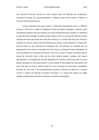
each tissue requires a variation of these to decellularise effectively. The various steps in
different protocols can be divided into physical, chemical and enzymatic.
2.10.1 Techniques
An overview of the various protocol portions are given in papers by Gilbert et al. [68]
and Badylak et al. [67]. Most often a process to rupture the cell membrane will be used at the
beginning of the process. These processes can include thermal shock, ultrasonics and
mechanical disruption. The term mechanical disruption can also be applied to simply removing
cell rich unwanted tissue before further steps to increase efficiency.
Agitation and perfusion are used to introduce the chemical and enzymatic solutions to
the tissue, depending on the characteristics of the tissue (i.e. if it is highly vascularised,
thick/thin). The use of vascular perfusion can greatly increase the efficacy of the process. In
this case the valve is known to have little vasculature which can be isolated, mainly due to
muscle insertion in the leaflet [11] and with some vasculature based in the strut chordae [70]
and this will make this technique ineffective. It is a combination of these various mechanical](https://image.slidesharecdn.com/38e6f6e6-808d-47d7-b1bd-3ff471006261-150702142634-lva1-app6892/85/Stuart-Deane-Thesis-43-320.jpg)
![Stuart A. Deane Trinity College Dublin 2014
34
A paper which takes into account the
recellularisation properties specific to the
xenogeneic heart valve is Rieder et al. 2004
[71]. In their study they compared
decellularisation protocols with their
subsequent aptitude for recellularisation with
human endothelial cells. The results for SDS
treatment is initially promising with effective
decellularisation but they report massive cell
lysis during recellularisation, the results
indicate that residual SDS can be found even
after prolonged washout. Their protocol of
Trypsin/EDTA created a confluent endothelial
layer in recellularisation. They did note
detectable porcine cells however. A protocol
of Triton x-100 and sodium-deoxycholate
followed by a washing process of
DNAse/RNAse to remove residual nucleic acids
proved to be the most effective for both
decellularisation and recellularisation
processes.
A study which also compares various
decell methods on porcine valves is by Zhou et
al. 2010 [72]. In their results they find that the
sodium deoxycholate treatment (A) was the
only one of four protocols which left the
elastic and collagen fibres unaltered. “Group A
were treated with 1% sodium deoxycholate
(Sigma–Aldrich) in PBS (Phosphate buffer
solution) at 37 ˚C for 24 hours with an
additional 24 h washing in PBS at room
temperature was performed under continuous
Table 4 - Decellularisation Processes](https://image.slidesharecdn.com/38e6f6e6-808d-47d7-b1bd-3ff471006261-150702142634-lva1-app6892/85/Stuart-Deane-Thesis-45-320.jpg)
![Stuart A. Deane Trinity College Dublin 2014
35
shaking to remove cellular remnants”. Their conclusion being that only sodium deoxycholate
allowed comprehensive cell removal with satisfactory ECM conservation.
Another study by Honge et al. 2011 [73] describes the effectiveness of recellularising
and calcification of Deoxycholic acid (DOA) and Glutaraldehyde treated aortic pig valves in
vivo. They showed that the glutaraldehyde rendered the valves extremely susceptible to
calcification and to thrombosis development. The DOA treated valves, when explanted,
showed observable endothelial and fibroblast recellularisation.
There are numerous techniques to be considered as shown in Table 4. Based on the
results of the summarised studies treatment with SDS is incompatible with recellularisation
process. Protocols using DOA did show improved recellularisation and less ECM malalignment
overall. This research indicates that the two most effective protocols are Zhou (A) and Rieder
(3). It is difficult to differentiate the two as the results of Rieder mostly deal with
recellularisation and Zhou with structure, but they do differ in total decell time and Rieder is
longer by 48 hours. Also the protocol set out by Rieder is older by 6 years; therefore Zhou
protocol (A) is the chosen protocol.](https://image.slidesharecdn.com/38e6f6e6-808d-47d7-b1bd-3ff471006261-150702142634-lva1-app6892/85/Stuart-Deane-Thesis-46-320.jpg)
![Stuart A. Deane Trinity College Dublin 2014
36
2.10.2 Decellularisation Assessment
There will be various aspects to the assessment of the capacity for the component to
be implanted after the decellularisation process. As the process will not be ideal there will be
unwanted side effects including growth factor elimination, ECM disruption, residual chemicals
and non-complete nuclei removal. Another factor is the mechanical strength and how the
valve and sub-valvular apparatus will perform in vivo under loading. Assessing how the
changed mechanical loading and other in vivo effects affect the recellularisation will be an
iterative process.
To fixate the tissue samples for examination a number of methods are described;
fixation in glutaraldehyde [71], fixation in formaldehyde [72-74] and snap freezing in liquid
nitrogen at -80˚C [25]. After fixation all samples are embedded in wax in preparation for
analysis.
In order to be determined fully decellularised the components which have been
shown to cause an immune rejection must be removed. Many of the techniques used to assess
the efficacy of the process are based on measuring the denuclearisation of the tissue. The
techniques based on evidence of avoiding adverse cell and host responses in studies are a
measurement of less than 50 dsDNA per milligram ECM dry weight, less than 200 (bp) DNA
fragment length and a lack of visible nuclear material in tissue sections stained with 4’,6-
diamidino-2-phenylindole (DAPI) or H&E (hematoxylin and eosin) [69, 75]. It is noted however
that the intracellular and membrane components also include the antigens which have been
shown to invoke immune rejection.
The next issue to investigate is the structural integrity of the ECM. This can be done by
staining, using various chemicals which will fluoresce during histology. Many studies analyse
collagen and elastin structure; using polyclonal rabbit IgG, 1:20 Monosan (Collagen type I & III)
[25, 71], Monoclonal anti-elastin, elastin trichrome and Movat Pentachrome staining [72] and
picrosirius red. The assumption being that the arrangement of collagen and elastin affects the
remodelling process. There is debate over the relevance of the composition and structure of
tissue with respect to site appropriate reconstruction [76]. It is largely recognised that ECM
does exert an influence on modulation of site specific function [77] and that collagen fibre
composition, individual to each tissue type is a critical factor in regulating its biomechanical
properties [76].](https://image.slidesharecdn.com/38e6f6e6-808d-47d7-b1bd-3ff471006261-150702142634-lva1-app6892/85/Stuart-Deane-Thesis-47-320.jpg)
![Stuart A. Deane Trinity College Dublin 2014
37
Further assessment can be carried out by conducting tensile tests on the leaflet tissue.
This can be carried out using a tensile testing machine modified to hold the leaflet tissue to
give an indication of the degradation of the mechanical properties during decellularisation.
This is especially important as the valve will be required to function immediately on
implantation, in this state, until recellularisation has taken place. Ideally testing of each
component would provide a better understanding of possible changes as the microstructure
changes from annulus to leaflet to chordae. An example of such a test for the leaflet is found
in a trial by Iwai et al 2007 [78]. In their test 5x10 (mm) Samples were tested at 10 (mm/min).
Another study carried out by Arbeiter et al also uses 5 (mm) wide samples but does not specify
length [79]. In the study by Barber et al the speed used was 4 (mm/s) [80]. Importantly tests
are carried out at different speeds and as the valve components demonstrate viscoelastic
properties this can significantly affect the mechanical properties. It will be necessary to
maintain a constant speed across mechanical tests.
The preconditioning phase of mechanical testing of tissue has been well documented.
The role of preconditioning is to mitigate error due to tissue handling and to diminish the
difference in subsequent load cycles by realigning the microstructure to a natural state, Carew
et al describe this as establishing a repeatable reference state [81]. There are a number of
studies which describe protocols for this stage of testing. Liao et al use 10 contiguous cycles
[82] whereas others have used cycling until a repeatable loading curve is observed [80]. In
their experiments Barber et al cycle between 200-400 (g) (≈2-4 (N)).
Similar uniaxial tensile tests have been carried out on the chordae. In the study by
Casado et al a test speed of 1 (mm/min) was used and the test was carried out at 37˚C in
physiological conditions [83]. They also describe preconditioning as described by Ritchie et al
2004 which involves cycling at a speed of 40 (% strain/s) (approximately 4mm/s) from 0-2 (N).
Liao et al use a speed of 4 (mm/s) also under physiological conditions and precondition until a
loading curve is repeatable.
There is much scope for further work in examining residual chemicals and growth factor
elimination. Also ideally a separate experimental setup to determine whether the different
tissue types present, leaflet, chordae and papillary muscles respond better to different
protocols.](https://image.slidesharecdn.com/38e6f6e6-808d-47d7-b1bd-3ff471006261-150702142634-lva1-app6892/85/Stuart-Deane-Thesis-48-320.jpg)
![Stuart A. Deane Trinity College Dublin 2014
38
2.11 Recellularisation
There are two methods to repopulate the scaffold with native cells. The first is based
on pre-surgical cell seeding using a bioreactor. The second method is the reliance on post-
implant diffusion of nutrients from the blood [26].
2.11.1 Reseeding
Although research has been conducted in this area the major issue in relation to this
project is that the time necessary to harvest the appropriate cells, culture them and then
reseed them is considerable. In a review by Badylak et al 2011 they discuss times differing
from 7 days to more than a month, depending on cell type and tissue type [67]. Clearly this is
not a possibility for an off-the-shelf product.
2.11.2 Diffusion
The question as to whether full endothelialisation can be accomplished in vivo due to
diffusion appears to be a question of tissue thickness. This oxygen and diffusion limitation of
tissue thickness in whole organ recellularisation is discussed in a study by Baptista et al 2009
[84]. The utilisation of in vivo recellularisation has been studied in relation to heart valves.
Research carried out by Quinn et al (2011) implanted decellularised pulmonary allografts
(n=8)to compare performance against bioprosthetics (n=4) and cryopreserved allografts (n=6)
in juvenile sheep [85]. The valves were explanted after 20 weeks for histological examination.
Their results show that autologous recellularisation was seen in decellularised valves but that
cells migrated primarily into the leaflet base and were rarely found in the middle or tip.
Endothelialisation occurred unevenly on the surface of the leaflet.
Another trial has shown similar results when implanting decellularised porcine valves
in the pulmonary valve location in canines [78]. The results show the spontaneous
endothelialisation of the luminal surface. They also show with H&E staining that at 2 months
the leaflets and adventitia (the outermost connective tissue covering of any vessel) were well
recellularised. At 6 months the valves were seen to be showing smooth muscle cells. These
results show viability of an in vivo recellularisation process without the need for in vitro cell
seeding and without the requirement of an intact vascular system. It should be noted that
these are short term results. A possible source of errors using this method is also mentioned
such that there must be a balance between resorption of the old matrix and synthesis of the
new matrix to reduce the likelihood of mechanical degradation.](https://image.slidesharecdn.com/38e6f6e6-808d-47d7-b1bd-3ff471006261-150702142634-lva1-app6892/85/Stuart-Deane-Thesis-49-320.jpg)
![Stuart A. Deane Trinity College Dublin 2014
39
The mitral valve is found in the systemic circuit, not the pulmonary as in the examples
above. This means that the valve will be subject to higher pressures and thus larger shear
forces which may affect in vivo recellularisation.
2.12 Sterilisation and Storage
2.12.1 Sterilisation
The Issue of sterilising heart valves is not new. A study carried out by Gall et al (1995)
outlines the recommendations made by an institution with 25 years of experience (1969-1994)
[86]. They recommend the use of incubation at 37˚C for 6 hours in a mixture of antibiotics
including penicillin and streptomycin. They say that valves which are refrigerated at 4˚C after
this sterilisation can be stored for up to 72 days and that storage for longer requires
cryopreservation. Another interesting recommendation is that specimens of tissue collected at
“trimming” must be sent for culture. This will allow knowledge of sterilisation to be compared
with patient progress. A follow up to this established that valves which are not to be
implanted within 1 to 2 days should be cryopreserved in order to remain viable [87]. It is noted
that viability was measured pre-implantation using autoradiography to assess cell function.
The use of gamma irradiation for sterilisation of medical devices is well known. Research
by Hafeez et al 2005 shows that Gamma irradiation has a significant detrimental effect on the
mechanical properties of samples of bovine pericardium [88]. The research theorises that the
pre-treatment process before irradiation has an effect on the damage experienced. This was
determined because the results measured are different from the conclusion of other trials
conducted.
2.12.2 Storage and Preservation
The shortfalls in the viability of cryopreserved valves as discussed previously and
established by Ali et al 2004 [22] conclude that all valves after cryopreservation were found to
be unviable at explant. Their definition appears to be that acellular and unviable are
interchangeable. Further work discussed how these homografts work by utilising the foreign
body response to sheath the valve and creates a pliable layer which encapsulates the leaflet](https://image.slidesharecdn.com/38e6f6e6-808d-47d7-b1bd-3ff471006261-150702142634-lva1-app6892/85/Stuart-Deane-Thesis-50-320.jpg)
![Stuart A. Deane Trinity College Dublin 2014
40
[89]. This effectively cuts off the cells in the leaflet tissue causing apoptosis. The durability of
these valves is limited by calcification. A more experimental technique is ice-free
cryopreservation which has shown greater ECM preservation due to the lack of formation of
ice [90]. The results of this trial are promising but more research must be carried out to make
it a practical substitute.
An alternative to cryopreservation is freeze drying. The trial carried out by Curtil et al
detail a protocol for freeze drying of porcine pulmonary valve leaflets [91]. Their results show
how the process and rate of cooling affected the structure of the leaflets. Although they do
allow that their process is not ideal for preservation. They do succeed in creating a porous
scaffold which is appropriate for rapid penetration by fibroblasts, but they show that the
internal pores do not communicate with the surface. The research carried out by Hafeez et al
2005 reports that there is minimal effects on mechanical properties due to freeze drying.
Once again it is presumed that these processes, both sterilisation and storage will have
effects on each other, the recellularisation process and will be affected by the decellularisation
process in turn. The process to produce the ideal preserved decellularised xenograft will be
some combination of the preceding techniques and finding the ultimate protocol will be an
iterative process.](https://image.slidesharecdn.com/38e6f6e6-808d-47d7-b1bd-3ff471006261-150702142634-lva1-app6892/85/Stuart-Deane-Thesis-51-320.jpg)
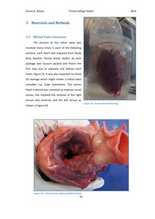
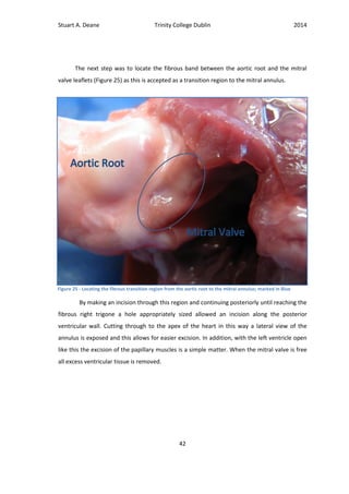
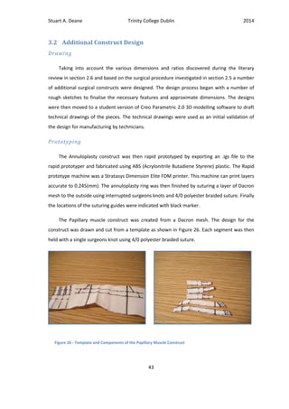
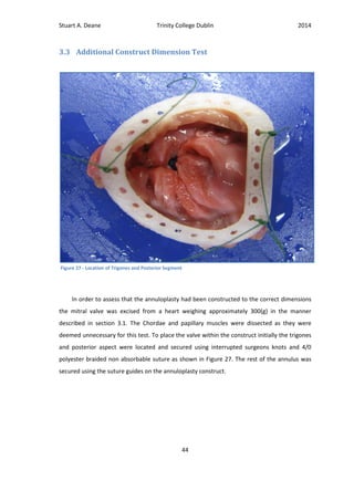
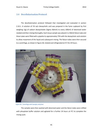
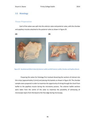
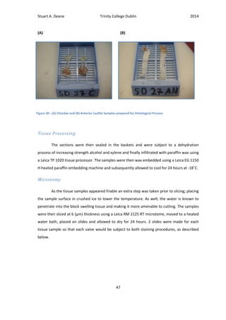
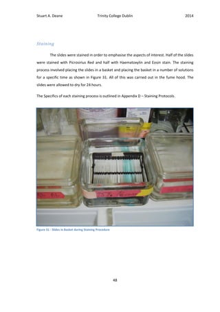
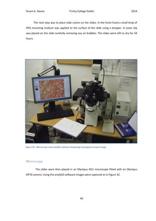
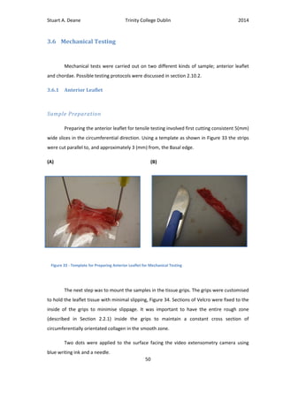
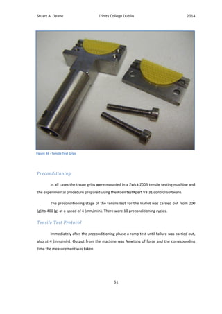
![Stuart A. Deane Trinity College Dublin 2014
52
3.6.2 Chordae
Sample Preparation
The chordae samples were chosen based on a number of criteria. As described by Lam
et al there are several classification of chordae [92]. As the structure of each chordae type
differs in both morphology and interaction with the valve leaflet the decision was made to use
the basal, or rough zone, chordae for consistency and because they are abundant. The
papillary muscle heads of the samples, as shown in Figure 29 (B), were split. Next the minor
branches of the chords were cut with approximately 1.5-2(mm) left on the main chord so as
not to cause a stress concentration. Finally the leaflet was cut so that adequate tissue could be
enclosed in the grip mount.
Again the grip mounts were custom made to hold the tissue with minimal slippage.
The grip holding the papillary muscle was equivalent to the anterior leaflet grip mounts. The
grip which held the leaflet was designed so as to remove the stress concentration presented
when the grip closed on the chord. This was achieved by wrapping the chord around a bar at a
distance from the grip as shown in Figure 35. Once again two ink dots were applied.
(A) (B)
Figure 35 - Tensile Grip Mount for Chordae Test (A) Dismantled and (B) with Leaflet secured](https://image.slidesharecdn.com/38e6f6e6-808d-47d7-b1bd-3ff471006261-150702142634-lva1-app6892/85/Stuart-Deane-Thesis-63-320.jpg)
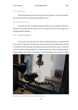
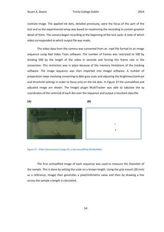
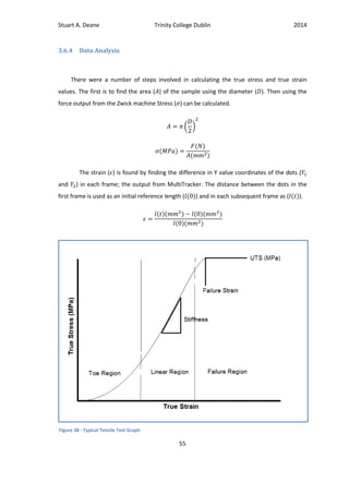
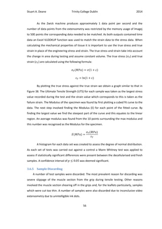
![Stuart A. Deane Trinity College Dublin 2014
57
4 Results
4.1 Additional Constructs
4.1.1 Annuloplasty
It was thought that the design of a modifiable “One-size-fits-all” annuloplasty would
further standardise the surgical procedure. With this in mind a constant inner orifice based on
the minimum expected intervalley (IV) ratio of a recipient valve could be exploited. This is
coupled with a modifiable outer edge based on the maximum expected mitral valve size. The
Major dimensions were taken from those found in the literary review. This means that the
range of intervalley dimensions expected are 30-36 (mm). Therefore the maximum outer IV is
45 in order to leave a 6 (mm) modifiable lip, 3 (mm) on either side, and a 7 (mm) overlap for
suturing to the donor annulus, 3.5(mm) on either side. This results in a constant EOA
(Estimated Orifice Area) of 6.4 (cm2
) which is larger than all available mechanical and
bioprosthetics [93]. As can be seen in the drawing a strengthening rib is positioned on the
inside overlap to add strength. The exact dimensions of this rib will need to be specified by in
vitro or finite element modelling. The guide holes along the inside are used to standardise the
Figure 39 - Mitral Annulus technical Specifications](https://image.slidesharecdn.com/38e6f6e6-808d-47d7-b1bd-3ff471006261-150702142634-lva1-app6892/85/Stuart-Deane-Thesis-68-320.jpg)
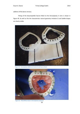
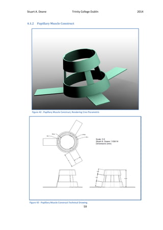
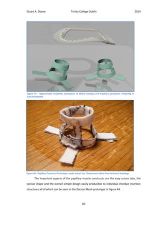
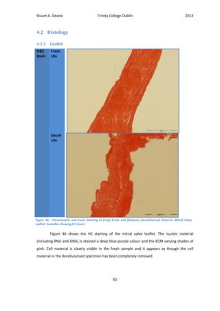
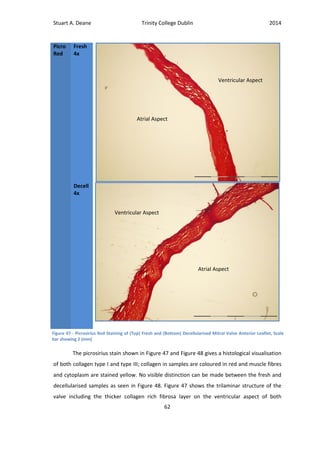
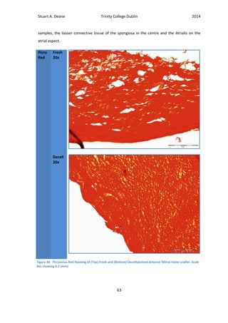
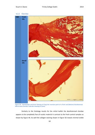
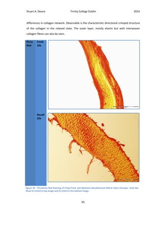
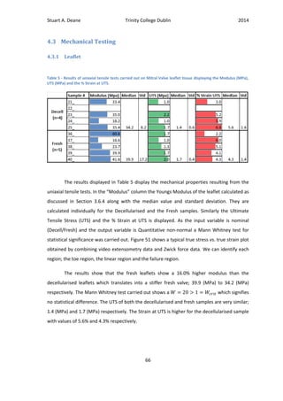
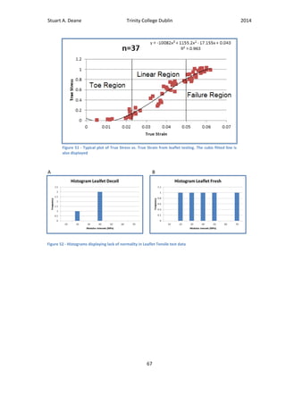
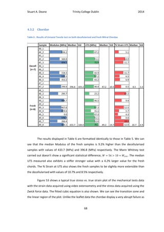
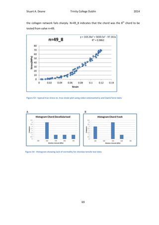
![Stuart A. Deane Trinity College Dublin 2014
70
5 Discussion
The overall objective of this project was the development of a bioengineered
decellularised xenograft for mitral valve replacement. In the beginning some major ideal
characteristics which the device would require were outlined. These involved standardising
the surgical procedure to maintain the xenograft as a feasible option, retaining the natural
hemodynamics of the heart, maximising availability of the device, long implanted lifetimes,
lack of anticoagulation therapy, lack of immune reaction and importantly viability to repair and
regrow due to the natural remodelling process of the body.
5.1 Additional Constructs
The research into the current treatments for mitral valve replacement indicated that the
primary reason the homograft was not in more widespread use was the intricate and time
consuming surgical procedure [15]. With this in mind a thorough investigation into the
techniques used was undertaken; Section 2.5 Surgical Technique. From this a number of areas
were highlighted as being difficult, irregular and carried out based largely on surgeons
intuition. The first issue arose in the analysis of presurgical imaging techniques. The valve must
be chosen and prepared before surgery. The approximate sizing and degree of damage must
be determined using trans-esophageal echocardiography [9, 14]. As outlined in Section 2.6 the
imaging process is itself quite difficult due to the gradual change from myocardium to valve
leaflet. These images can often be uninformative and ambiguous. One study states that the
majority of early failures were caused by patient mismatch and could have been avoided by
using transoperative sizing [22]. It was thought that intraoperative sizing would be a more
definitive process and as it is already utilised for choice of annuloplasty would not increase the
number of surgical steps or instruments [14, 15]. The device therefore must be available
immediately during surgery; an off-the-shelf (OTS) product. The implications of this become
more evident in the design process later on.](https://image.slidesharecdn.com/38e6f6e6-808d-47d7-b1bd-3ff471006261-150702142634-lva1-app6892/85/Stuart-Deane-Thesis-81-320.jpg)
![Stuart A. Deane Trinity College Dublin 2014
71
5.1.1 Papillary Muscle Construct
There are three steps involved in the implantation of a homograft. The first is the
insertion of the papillary muscles. In order for the device to simplify the papillary insertion
procedure it must be an improvement on the existing technique detailed in Section 2.5.3 and
shown in Figure 12. Here we can see that approximately 9 separate sutures are placed in each
of the papillary muscle. The placement is also restricted to the natural geometry of the
patient, particularly relying on the native papillary muscle for fixation. Due to the variability of
individual chordae and papillary muscle an OTS device designed to support all must conform
to a standard size. The use of a xenograft will mean that chordae morphology will not match
exactly to the geometry of the natural valve [62]. The decision was made to harvest a standard
valve type and size utilising a regular papillary muscle arrangement (type 1 as described in
Section 2.5.1) and implanting the valve in the natural geometry of the donor valve, which is
known to reduce stress in the subvalvular apparatus [63]. The design presented (Figure 42) for
the papillary muscle construct addresses these subjects. The first benefit of the papillary
muscle construct will be found in placing of the papillary muscles as it is not restricted to using
the recipient papillary muscles. As the donor valve is to be kept in its natural geometry a
structure can be utilised to maintain the geometry throughout the surgical procedure,
reducing the risk of misplacement and subsequent abnormal stress on the chordae. As well as
this the placement allows for contact between the papillary muscle and ventricular wall, this
could allow nutrient and cell diffusion in the remodelling process. This construct can be
compared with the Medtronic physiologic valve shown in Figure 22. The Dacron sewing tubes
on this product do not allow for contact of the papillary muscle with native tissue. Although
the glutaraldehyde fixed valve in question would be unable to remodel. Secondly the three
“easy suture” tabs will reduce the time and intricacy of the securing process by reducing the
number of sutures necessary, but also by mitigating suture placement issues surrounding the
chordae insertion points, which can cause erosion [15]. It is thought that securing of the device
will be improved by utilising the cone shape of the papillary muscle as it spreads from the tip
to the wider base which is attached to the myocardium. Lastly because the device will interact
with the papillary muscle, it must be permeable to allow diffusion of nutrients and cells from
the blood to allow remodelling. As can be seen in Figure 44 the device is easily manufactured
from a Dacron® mesh.](https://image.slidesharecdn.com/38e6f6e6-808d-47d7-b1bd-3ff471006261-150702142634-lva1-app6892/85/Stuart-Deane-Thesis-82-320.jpg)
![Stuart A. Deane Trinity College Dublin 2014
72
5.1.2 Annuloplasty Construct
Conventionally the next two steps of the surgical procedure involved, firstly, securing
the donor valve annulus which is followed by an annuloplasty. With the use of an OTS valve it
is possible to combine these steps, thereby reducing the surgical procedure significantly. This
would not be possible using a traditional valve as preoperative sizing was used for the valve
but intraoperative sizing was used for the annuloplasty. As previously mentioned the decision
was made to utilise an OTS one-size-fits-all approach. What this means is that one valve must
fit all recipients, and therefore must be easily modifiable. It was found in Section 2.6 that the
components of the annulus geometry could be described as ratios of the intervalley distance.
For this reason this is the dimension used to describe the design. It was also discovered that a
regular valve range of 30-36(mm) intervalley distance could be expected. The design
presented satisfies this range by maintaining a constant inner IV distance of 30 (mm) and by
having a modifiable outer lip, exact dimensions detailed in Section 4.1.1. As shown this will
allow a constant EOA of 6.4 (cm2
). It is important to note that all commercially available
mechanical and bioprosthetic devices have a smaller EOA than this with the Hancock
Bioprosthetic largest at 3.15 (cm2
) [93]. The benefits to the device recipient patient would be a
reduction in lower atrial pressure which would reduce the likelihood of atrial enlargement.
Another major feature of the annuloplasty construct is the shape. Research revealed
that the natural annulus conforms both to a D-shape when viewed from above [39] and also a
saddle-shape [40, 41]. The annulus design as seen in Figure 39 utilises these features to
conform the valve to the natural geometry when implanted, reducing unnatural stress on the
subvalvular apparatus [42]. As well as this it was noted that the annulus undergoes a change in
shape throughout the cardiac process. This involves a contraction of the posterior segment
during systole and a folding during end systole [40, 45, 47]. These factors indicate that the
annulus should be able to deform correctly to reduce subvalvular apparatus stress [47]. With
this and a fatigue life of (cycles) a material choice of polyester was made. Polyester
emulates the mechanical properties of the annulus adequately and which would survive for
approximately 20 years in vivo. This choice is popular amongst commercially available
bioprosthetics, which have polyester sewing rings. Interestingly all major market leaders have
released unaccompanied annuloplastys with similar characteristic saddle and D-shapes.
Caprentier Edwards Physio II [94], St. Jude Medical™ Rigid Saddle Ring [95] and the Medtronic](https://image.slidesharecdn.com/38e6f6e6-808d-47d7-b1bd-3ff471006261-150702142634-lva1-app6892/85/Stuart-Deane-Thesis-83-320.jpg)
![Stuart A. Deane Trinity College Dublin 2014
73
Profile 3D® Annuloplasty Mitral Valve Ring [96] all utilise the natural shape of the valve and
suggest the reduction in chordal forces as the reason.
Other less crucial features which are evident in the design presented include the
surgical guides (holes) placed around the annulus to allow for a more uniform, standard,
placement procedure. As well as this, as can be seen in Figure 40, the annulus construct is
finished by covering in a Dacron mesh to aid in biocompatibility. A strengthening rib is also
visible which would distribute the loading more evenly.
There are a number of issues which due to time constraints could not be dealt with. As
much of the work on constructs was research based, there was little testing of the concept.
What is shown is that the design is possible and although much in vitro testing would be
necessary before animal/human trials each component can be quickly constructed and is
theoretically highly functional. There were also some thoughts for evolutions of the design, for
example, if the annuloplasty were to be made from a resorbable material the valves would be
much more suitable to paediatric patients as it could integrate fully and grow with the heart.
As well as this the scaffold which would be necessary to implant the valve whilst retaining the
donor geometry will need to be considered. This is outside the scope of this project.
From this it can be found that the surgical procedure involved in implanting a xenograft
mitral valve could be standardised. With the use of easily placed papillary muscle constructs
and a modifiable annuloplasty construct a “one-size-fits-all” “off-the-shelf” valve is possible
and achievable. What this means is several of the original criteria are accomplished. Having
already discussed the easy surgical procedure, but also because we can now feasibly use a
xenograft we have the advantage of availability. This is in contrast to homografts which have
limited supply of suitable donors [27]. The criteria of retaining the natural hemodynamics is
also accomplished as the donor valve will include the characteristic subvalvular apparatus. This
will be an advantage over all commercially available bioprosthetics and mechanical valves and
it is known that recorded leaflet motion is comparable to natural mitral valves [32]. Another of
the conditions, a lack of anticoagulation therapy, is also satisfied by this arrangement as the
materials used in the considered procedure will not cause thrombosis.](https://image.slidesharecdn.com/38e6f6e6-808d-47d7-b1bd-3ff471006261-150702142634-lva1-app6892/85/Stuart-Deane-Thesis-84-320.jpg)
![Stuart A. Deane Trinity College Dublin 2014
74
5.2 Decellularisation
The major criteria which have not yet been addressed are the expected long lifetimes,
lack of immune reaction and viability. We have mentioned that the use of a xenograft over a
homograft will mean a greater supply due to the lack of availability of the homograft. The
negative aspect of using untreated xenogeneic material is that implantation in human subjects
invariably results in hyperacute rejection [65]. This will mean that the valve will be subject to a
rejection process gradually breaking it down and leading to failure. In order to avoid this
outcome a decellularisation process must be completed. The ideal decell process is intended
to successfully remove the immunogenic nucleic material whilst preserving the ECM [66, 67]. A
successfully decellularised valve will not provoke an immune reaction when implanted. The
ECM is shown to provide cues attracting appropriate recellularisation which is essential in the
remodelling process [68, 76, 77]. Badylak et al describe remodelling as the complete
replacement of donor tissue with site specific native tissue [69]. In an ideal process after decell
the tissue will remain viable to recellularisation. This means that the implanted valve is
replaced and a new living valve is regrown in its place due to the natural remodelling of the
body. As discussed in Section 2.10.1 there are many different decell protocols and their use is
dependent on the tissue type and required end use of the material. The protocol used in this
project was described by Zhou et al uses mechanical agitation and an ionic detergent
Deoxycholic Acid (DOA) to solubilise the cell membrane followed by a PBS rinsing cycle to
remove the remnants [72]. This protocol was chosen as there were a number of studies
relating DOA to the decell of valves, in successfully retaining their important microstructure
[72] and also in effective recellularisation [71, 73]. A Valve which has been successfully
remodelled in this way could be expected to endure for long periods of time supported by the
natural processes of the body, leading to long lifetimes.
An important aspect of the decellularisation process is the assessment of its successful
completion. There are a number of criteria which must be considered including the mechanical
properties, the microstructure and the detection of remaining nucleic material. The
mechanical properties of the valve are important as in our OTS model the valve will be
required to function immediately on implantation. Because of this it is important to compare
the decellularised valve to native tissue to ensure the mechanical properties have not been
substantially changed.](https://image.slidesharecdn.com/38e6f6e6-808d-47d7-b1bd-3ff471006261-150702142634-lva1-app6892/85/Stuart-Deane-Thesis-85-320.jpg)
![Stuart A. Deane Trinity College Dublin 2014
75
5.2.1 Mechanical testing
To test the mechanical properties a uniaxial tensile test was carried out. There are many
test protocols dependent on tissue type and the properties required which are discussed in
Section 2.10.2.
Leaflet
The properties tested are displayed in Table 5. The median modulus of the fresh valves
was shown to be 16% higher than the decellularised valve with values of 39.9 (MPa) and 34.2
(MPa) respectively. As well as this the corresponding Ultimate Tensile Strength (UTS)
measured were 1.7 (MPa) and 1.4 (MPa); a difference of 21.4%.This indicates that the
decellularisation process is reducing the mechanical properties of the valves and that the fresh
valve is slightly stiffer and stronger. A review by Badylak et al recently considers that the
decellularisation of tissue using ionic detergents (such as DOA) can lead to collagen denaturing
and a reduction in growth factors and GAG content [69]. The denaturing of collagen involves
slowly breaking it down and fully denatured collagen is gelatin. This consequence of the decell
process is most likely the cause of the slightly lower mechanical properties recorded as the
modulus is recorded during the linear phase attributed to collagen. The typical load
displacement diagram shown in Figure 51 is representative of that found in literature. As
described by Tower et al the toe region is demonstrative of the collagen structure uncrimping
and aligning while the other components
bear the load [97]. The linear region then
demonstrates the aligned collagen
becoming the primary load bearing element.
Finally the failure region shows failure of the
collagen fibres. This is illustrated in Figure
55. When analysing the data a cubic curve
was fitted. This was chosen because of
failure pattern resulting from the three
regions and is believed to represent the data
most accurately.
A finite element model analysis of the mitral valve simulated under normal conditions
found that the stress in the belly of the anterior leaflet reached 0.4-0.6 (MPa) [98]. As well as
this Liao et al indicated that a load of 60 (N/m) (approximately 0.6 (MPa)) represented
Figure 55 - Load Displacement Curve Illustrating the
uncrimping of Collagen in relation to the three regions](https://image.slidesharecdn.com/38e6f6e6-808d-47d7-b1bd-3ff471006261-150702142634-lva1-app6892/85/Stuart-Deane-Thesis-86-320.jpg)
![Stuart A. Deane Trinity College Dublin 2014
76
maximum systolic pressure [82]. This indicates that the tested valves (reaching 1.4 and 1.7
(MPa)) are well within the safe region and are not in danger of failure. Overall it appears that
although the decell process is reducing the mechanical properties, the difference is not
significant. The mechanical properties recorded by Arbeiter for the aortic valve are a modulus
of 28±4 (MPa) and a UTS of 4±2.6 (MPa) [79]. These values fall reasonably close to those
measured here and the discrepancies could be explained by a difference in testing conditions.
As their testing procedure does not mention video extensometry this could mean possible
slippage decreasing the Youngs modulus. As well as this the elongation at breakage was
measured as 23±13 (%) whereas the value found in this study was 4.3% also indicating possible
slippage. Another factor may be that the fibrosa is relatively thicker in the mitral valve
increasing the collagen to elastin ratio. The failure strength recorded by Barber et al is 981
(N/m), this is .981 (N/mm) and converting to MPa by dividing by and average leaflet thickness
(≈.5 (mm)) we get 1.962 (MPa) which is similar to the result found in this study [80]. It is noted
that the average measured thickness of the valve may have been a limitation here as the value
measured by Grande-Allen et al is almost double at 2.15±1.14 (mm) [99]. Mitigating a
difference like this would certainly bring the measured closer to the UTS measured in this
study.
A Mann Whitney test carried out on the leaflet data shows that the statistical
difference in the data groups (decell and fresh) is insignificant as . A
Mann Whitney Test is a non-parametric test for unpaired data sets. The data was thought to
be non-parametric as the histograms seen in Figure 52 do not visually represent normally
distributed data. For this reason and the small data set the median of the data was used
instead of the mean as the mean could be greatly influenced by outliers with the median being
more robust and sensible. This small data set remains one of the limitations of the experiment.
The modulus was calculated in a way that was reproducible over all of the data
samples, as described in Section 3.6.4. At first a linear trendline was fitted to the linear region
and the slope of this line was thought to be representative of the modulus. This technique was
inconsistent as the linear region was identified only visually.
Chordae
The results for the chordae are similar to the leaflet results and can be found in Table
6. Once again the histograms in Figure 54 show a lack of normality in the distribution due to](https://image.slidesharecdn.com/38e6f6e6-808d-47d7-b1bd-3ff471006261-150702142634-lva1-app6892/85/Stuart-Deane-Thesis-87-320.jpg)
![Stuart A. Deane Trinity College Dublin 2014
77
small study numbers. For this reason the data is analysed in the same non-parametric way as
the leaflet data described above.
The modulus for the decellularised chordae was measured as 9.2 (%) lower than that
of the fresh valves with 396.8 (MPa) and 433.7 (MPa) respectively. Again a Mann Whitney test
concludes that the difference in the data sets is not significant; . As well
as this the UTS measured was measured for the decellularised chordae as 4.2 (%) lower than
the fresh chord with values of 47.2 (MPa) and 49.2 (MPa) respectively. The percentage strain
at failure measured also shows the fresh valve to be slightly stiffer with values of 8.5 (%) for
the fresh and 10.7 (%)for the decellularised chord. Overall it can be seen that the
decellularisation process has reduced the mechanical properties of the chordae, but not in a
significant manner. Again the likely cause for this is the denaturing of the collagen in the use of
ionic detergents reported by Badylak et al [69].
Physiological conditions experienced by the chordae are reported by Rim et al as
ranging from 0.3-1.1 (MPa), using their computational model [98]. Results measured by Siefert
for the strut chordae are given as 0.71±0.08 (MPa) largely agreeing with Rim. A study by Liao
et al suggests that the thicker chordae are less strong and more extensible than thinner
chordae due to the crimp period [100] and as the effects are measured on the basal chordae it
is expected that they will be under more pressure. Lomholt et al report that the primary
chordae are under 3 times the tension of secondary chordae [101], even so the UTS measured
are far outside of this range. Ritchie et al report the largest strain experienced during the
cardiac cycle as 4.29 (%) for the strut chordae. It is expected that the basal chords would be
less extensible and comparing this with the typical force/displacement curve in Figure 53 this
falls well within the toe region and thus the elastic region where the chord can return its
original shape without damage.
The reported modulus figures by Casado are 233 (MPa) with an average area of 0.35
(mm2
) [83] and Barber as 132 (MPa) with an average area of 0.8 (mm2
) [102]; both smaller
than what is measured in this study. Barbers area is 3.3 times that found in this study and
Casados is 1.45 times higher. The smallest area group for mitral chordae reported by Liao is
0.5-1 (mm2
) which is still twice the area recorded in this study of 0.24±0.05 (mm2
).
Interestingly if these differences are multiplied by the reported moduli it is found that Barbers
changes to 435.6 (MPa) (132×3.3) and Casado to 337.9 (MPa) (233×1.45), which are very
similar to the values reported here. A report by Sasaki and Odajima suggests that the modulus](https://image.slidesharecdn.com/38e6f6e6-808d-47d7-b1bd-3ff471006261-150702142634-lva1-app6892/85/Stuart-Deane-Thesis-88-320.jpg)
![Stuart A. Deane Trinity College Dublin 2014
78
of collagen is 430 (MPa) [103] and as the chordae are largely aligned collagen this figure also
agrees with this study. These figures suggest that differences in diameter measurement may
have led to measured modulus differences. Overall it can be concluded that the
decellularisation process has not affected the mechanical properties of the chordae in a
significant way.
As mentioned a limitation of the mechanical studies is the small sample number. Steps
to mitigate the non-parametric data have been taken to reverse the effects. Another test to be
considered in the future which may yield further interesting results would be tensile tests on
the decellularised annulus as it may behave differently to the leaflet and the chordae.
5.2.2 Microstructure
As previously discussed it is important to preserve the ECM of the valve as it has been
shown to provide cues for remodelling in vivo. On a macroscopic level the structure of the
leaflet tissue is seen to be largely intact in both the fresh and decellularised samples, as seen
in Figure 47. The leaflet structure is very similar to images found by Stephens et al [104] who
describe the fibrosa, spongiosa and atrialis layers as described in Section 2.2.1. The
Microscopic structure showing interaction of the collagen network is very similar to that
shown by Movat Pentachrome staining in a study by Baraki et al for a decellularised aortic
valve to be implanted in sheep for in vivo recellularisation [105]. The results for Barakis study
do show successful recellularisation and it can be inferred that the collagen network in this
study could be similarly attractive. From this it is assumed that the collagen network has not
been substantially affected by the decellularisation process. Interestingly apparent damage to
the both the decellularised leaflet (Figure 47) and the decellularised chordae (Figure 50) can
be seen. The leaflet appears to be damaged on the atrial aspect and the chordae on the outer
sheath. Both of these areas are elastin rich. Following on from this it would be important to
carry out a movat pentachrome stain to ascertain changes to the elastin structure as this is a
crucial feature of the atrialis on the atrial aspect and the chordal sheath. Due to time
restrictions it was not possible during this study.
In Figure 50 the picrosirius stains for the chordae can be seen. An interesting feature
noticeable more so in the image of the decellularised chordae are the wavy lines running
perpendicular to the length of the chordae. These lines represent the crimped collagen](https://image.slidesharecdn.com/38e6f6e6-808d-47d7-b1bd-3ff471006261-150702142634-lva1-app6892/85/Stuart-Deane-Thesis-89-320.jpg)
![Stuart A. Deane Trinity College Dublin 2014
79
structure which is characteristic of the chordae as described by Liao et al [100]. The crimped
structures are sliced in a flat plane leaving only horizontal lines visible. As well as this the outer
sheath made of collagen and elastin can be seen. Again there is little visible difference to the
collagen structure and the assumption is that the decellularisation process made no
substantial change to the collagen structure.
5.2.3 Decellularisation
The hematoxylin and eosin (HE) staining presented in Figure 46 and Figure 49 are
perhaps the most important assessment of how successful the decellularisation process has
been. The HE stain reveals remaining nuclear material and therefore can give a visual
representation of the possible immune response of a xenogeneic material when implanted
[69, 75]. A clear difference in both the leaflet and chordae images can. Cellular material
(stained in blue) is abundantly visible in the fresh samples and appears to be completely
removed in the decellularised samples, indicating that the decell process has been a success.
Although the chordae image is of the insertion point and not the mid-chordae as in the decell
image Ritchie et al reported that HE staining on fresh valves revealed fibroblasts distributed
throughout the inner and outer layers of the chordae [70]. From this a successful
decellularisation can still be declared based on Figure 49. Rieder et al show images of
successfully decellularised leaflet tissue and they are comparable to those shown here [25]. In
a study carried out by Driessen et al Tissue Engineered Heart Valves (TEHV) were constructed
and decellularised before implant. The HE images in that paper were deemed a successful
decellularisation despite (minimal) visual cellular material present, these valves were shown to
recellularise autologously in vivo when implanted. Decellularised aortic ovine valves implanted
for in vivo recellularisation presented by Baraki et al also gave similar results [105]. The
viability is the important aspect associated with a successful decellularisation. The in vivo
autologous recellularisation, as recorded in these studies [29, 105], is inextricably linked to
remodelling and regrowth. This natural regrowth will then lead to the necessary long lifetimes
as the valve is supported by the body.
Following from these results it would be important to carry out DNA assays to determine
residual DNA which would give a clearer understanding of remaining immunogenic material,
due to time constraints this could not be carried out during this study. As discussed in Section
2.10.2 the recommended amount is 50 dsDNA per milligram ECM dry weight [69]. A major](https://image.slidesharecdn.com/38e6f6e6-808d-47d7-b1bd-3ff471006261-150702142634-lva1-app6892/85/Stuart-Deane-Thesis-90-320.jpg)
![Stuart A. Deane Trinity College Dublin 2014
80
limitation to this study was found when the muscles were viewed after the HE stain, it is clear
that neither the papillary muscles nor the muscle from the ventricular annulus were
decellularised. Separate research is ongoing into this area as the thicker muscle tissue is much
more difficult to process. It would also be important to test for residual chemicals and the
possible elimination of growth factors as described by Badylak [69].
As described here, all of the original criteria have been acknowledged. An improved
system for surgical procedure to establish the xenograft as a feasible alternative to available
bioprosthetics and mechanical valves was developed leading to availability of donors. Next the
condition of natural hemodynamics was established successfully as the xenograft retains the
characteristic subvalvular apparatus. An additional feature of both of these was the lack of
immune reaction due to the materials used. The decellularisation process was also shown to
be successful due to a lack of immunogenic material and the minimal disruption the ECM
indicating viability leading to long lifetimes would be possible. The next step of this process
would be to test the recellularisation potential of the valve. It would then be necessary to
measure the balance between resorption and remodelling to ascertain whether the valve can
survive in vivo long enough to complete the remodelling process. Furthermore, although the
preservation and storage was briefly described in Section 2.12.2 a more thorough investigation
into the available techniques and their possible effects on the properties mentioned would be
necessary.](https://image.slidesharecdn.com/38e6f6e6-808d-47d7-b1bd-3ff471006261-150702142634-lva1-app6892/85/Stuart-Deane-Thesis-91-320.jpg)

![Stuart A. Deane Trinity College Dublin 2014
82
Works Cited
1. Members, W.G., et al., Heart Disease and Stroke Statistics—2006 Update: A Report
From the American Heart Association Statistics Committee and Stroke Statistics
Subcommittee. Circulation, 2006. 113(6): p. e85-e151.
2. Cardiothoracic Surgical Outcome reports. 2013 [cited 2014 28 March]; Available from:
http://ctsurgery.stanford.edu/patient_care/outcomes_shc.html.
3. Nkomo, V.T., et al., Burden of valvular heart diseases: a population-based study. The
Lancet. 368(9540): p. 1005-1011.
4. Bourguignon, T., et al., Very late outcomes for mitral valve replacement with the
Carpentier-Edwards pericardial bioprosthesis: 25-year follow-up of 450 implantations.
The Journal of Thoracic and Cardiovascular Surgery, (0).
5. Young, M. Cardiovascular fitness training. 2008; Available from: http://www.swim-
teach.com/cardiovascular-fitness.html.
6. Medical Nursing. 2010 10th March]; Available from:
http://nursingmedic.blogspot.ie/2010/11/anatomy-of-heart.html.
7. Carpentier, A., Carpentier's Reconstructive Valve Surgery; From valve Analysis to Valve
Reconstruction. 2008: Saunders.
8. Marieb, E.N.a. and K.a. Hoehn, Anatomy & physiology. Fifth edition, International
edition. ed.
9. Acar, C., et al., Homograft replacement of the mitral valve: graft selection, technique of
implantation, and results in forty-three patients. The Journal of Thoracic and
Cardiovascular Surgery, 1996. 111(2): p. 367-380.
10. Hinton, R.B. and K.E. Yutzey, Heart Valve Structure and Function in Development and
Disease. Annual Review of Physiology, 2011. 73(1): p. 29-46.
11. Mulholland, M.D.L. and M.D.C.M.F.A.I. Gotlieb, Cardiac Valve Interstitial Cells:
Regulator of Valve Structure and Function. Cardiovascular Pathology, 1997. 6(3): p.
167-174.
12. Vahanian, A., et al., Guidelines on the management of valvular heart disease: The Task
Force on the Management of Valvular Heart Disease of the European Society of
Cardiology. European Heart Journal, 2007. 28(2): p. 230-268.
13. Chikwe, J., et al., A propensity score-adjusted retrospective comparison of early and
mid-term results of mitral valve repair versus replacement in octogenarians. European
Heart Journal, 2011. 32(5): p. 618-626.
14. Kalangos, A., et al., Mitral valve replacement using a mitral homograft. Multimedia
Manual of Cardio-Thoracic Surgery, 2011. 2011(0916).
15. Acar, C. and M. Ali, Homologous transplantation of the mitral valve: a review. The
Journal of cardiovascular surgery, 2004. 45(5): p. 455-464.
16. Blue Books Online. 2013; Available from: http://bluebook.scts.org/.
17. Gammie, J.S., et al., Trends in Mitral Valve Surgery in the United States: Results From
The Society of Thoracic Surgeons Adult Cardiac Database. The Annals of Thoracic
Surgery, 2009. 87(5): p. 1431-1439.
18. Valve Surgery Outcomes. 2011 [cited 2014 march 8th]; Available from:
http://my.clevelandclinic.org/Documents/heart/Outcomes/2011/05-valve-
disease.pdf.
19. Aupart, M.R., et al., Perimount pericardial bioprosthesis for aortic calcified stenosis:
18-year experience with 1133 patients. The Journal of heart valve disease, 2006. 15(6):
p. 768-75; discussion 775-6.](https://image.slidesharecdn.com/38e6f6e6-808d-47d7-b1bd-3ff471006261-150702142634-lva1-app6892/85/Stuart-Deane-Thesis-93-320.jpg)
![Stuart A. Deane Trinity College Dublin 2014
86
78. Iwai, S., et al., Minimally immunogenic decellularized porcine valve provides in situ
recellularization as a stentless bioprosthetic valve. Journal of Artificial Organs, 2007.
10(1): p. 29-35.
79. Arbieter, D., Suitability of porcine pericardial tissue for heart valve engineering:
Biomechanical properties. Biomedical Technology, 2012. 51(1): p. 882-883.
80. Barber, J.E., et al., Mechanical properties of myxomatous mitral valves. The Journal of
Thoracic and Cardiovascular Surgery, 2001. 122(5): p. 955-962.
81. Carew, E.O., J.E. Barber, and I. Vesely, Role of Preconditioning and Recovery Time in
Repeated Testing of Aortic Valve Tissues: Validation Through Quasilinear Viscoelastic
Theory. Annals of Biomedical Engineering, 2000. 28(9): p. 1093-1100.
82. Liao, J., E.M. Joyce, and M.S. Sacks, Effects of decellularization on the mechanical and
structural properties of the porcine aortic valve leaflet. Biomaterials, 2008. 29(8): p.
1065-1074.
83. Casado, J.A., et al., Determination of the mechanical properties of normal and calcified
human mitral chordae tendineae. Journal of the Mechanical Behavior of Biomedical
Materials, 2012. 13(0): p. 1-13.
84. Baptista, P.M., et al., Whole organ decellularization - a tool for bioscaffold fabrication
and organ bioengineering. Conf Proc IEEE Eng Med Biol Soc, 2009. 2009: p. 6526-9.
85. Quinn, R.W., et al., Performance and Morphology of Decellularized Pulmonary Valves
Implanted in Juvenile Sheep. The Annals of Thoracic Surgery, 2011. 92(1): p. 131-137.
86. Gall, K., et al., Allograft heart valve sterilization: A six-year in-depth analysis of a
twenty-five–year experience with low-dose antibiotics. The Journal of Thoracic and
Cardiovascular Surgery, 1995. 110(3): p. 680-687.
87. Gall BapplSc, K.L., et al., Allograft Heart Valve Viability and Valve-Processing Variables.
The Annals of Thoracic Surgery, 1998. 65(4): p. 1032-1038.
88. Hafeez, Y.M., et al., Effect of freeze-drying and gamma irradiation on biomechanical
properties of bovine pericardium. Cell and Tissue Banking, 2005. 6(2): p. 85-89.
89. Hopkins, R., From cadaver harvested homograft valves to tissue-engineered valve
conduits. Progress in Pediatric Cardiology, 2006. 21(2): p. 137-152.
90. Brockbank, K.M., et al., Ice-free cryopreservation of heart valve allografts: better
extracellular matrix preservation in vivo and preclinical results. Cell and Tissue Banking,
2012. 13(4): p. 663-671.
91. Curtil, A., D.E. Pegg, and A. Wilson, Freeze Drying of Cardiac Valves in Preparation for
Cellular Repopulation. Cryobiology, 1997. 34(1): p. 13-22.
92. LAM, J.H.C., et al., Morphology of the Human Mitral Valve: I. Chordae Tendineae: A
New Classification. Circulation, 1970. 41(3): p. 449-458.
93. Normal measurements of mitral valve protheses. 28 June 2010 [cited 2014 5th June];
Available from:
http://www.echopedia.org/wiki/Normal_measurements_of_mitral_valve_protheses.
94. Edwards. Carpentier-Edwards Physio II Annuloplasty Ring. 2014 [cited 2014 19th
Aug.]; Available from: http://www.edwards.com/products/rings/pages/physioii.aspx.
95. Medical, S.J. St. Jude Medical Rigid Saddle Ring with EZ Suture Cuff. 2014 [cited 2014
19th Aug]; Available from: http://professional.sjm.com/products/sh/valve-
repair/rigid-semi-rigid-rings/st-jude-medical-rigid-saddle-ring-with-ez-suture-
cuff#tech-specs.
96. Medtronic. Profile 3D Annuloplasty Mitral Valve Ring. 2014 [cited 2014 19th Aug];
Available from: http://www.medtronic.com/mics/valve-profile-3d.html.
97. Tower, T., M. Neidert, and R. Tranquillo, Fiber Alignment Imaging During Mechanical
Testing of Soft Tissues. Annals of Biomedical Engineering, 2002. 30(10): p. 1221-1233.](https://image.slidesharecdn.com/38e6f6e6-808d-47d7-b1bd-3ff471006261-150702142634-lva1-app6892/85/Stuart-Deane-Thesis-97-320.jpg)
![Stuart A. Deane Trinity College Dublin 2014
88
Appendix A – Effects of Deoxycholic acid
Decellularisation on Porcine Mitral Valve Chordae
Stuart A. Deane, Trinity College Dublin.
Abstract - This paper investigates the
effect of decellularisation using sodium
deoxycholate on the chordae of a porcine
mitral valve. Important aspects examined
are the resultant mechanical properties
and the changes to the Extra Cellular
Matrix as well as remaining nuclear
material. These factors could affect
performance if the chordae were to be
implanted as an unaccompanied device or
in conjunction with a replacement heart
valve. It was found that the
decellularisation process was a success and
as the mechanical properties did not
change significantly, the ECM appeared
unaltered and no visual signs of remaining
nuclear material were exhibited.
Introduction – The failure of the chordae
tendinae is a common complaint in all ages
but especially in the middle aged [1]. Their
failure leads to prolapsing of the valve
(MVP) and subsequently to the mitral
regurgitation associated with left
ventricular enlargement and heart failure.
There are a number of surgical procedures
for the treatment of MVP. The two major
categories are mitral valve
repair (MR) and replacement (MVR). MVR
is reserved for cases only where MR is not
applicable due to extensive damage to the
leaflet and subvalvular apparatus. Stanford
school of medicine report 57% as MR [2].
Reasoning for this is given as the mortality
rate associated with MVR is much higher;
4.23 and 1.99% respectively [3].
There are repair techniques for
mitral valve failure associated with failure
of the chordae in particular. These include
shortening the chordae or replacing them
with artificial PTFE chords [4]. It is thought
that a replacement chord which was
constructed from a decellularised porcine
chordae may have the ability to integrate
better with the native tissue, recellularise
and remodel.
MVR the chordae would be part of
an integrated decellularised mitral valve to
be implanted whole into patients. A
replacement like this would be expected to
integrate with the native geometry,
recellularise and remodel. The
investigation of properties of the chordae
is intrinsic to the success of such a valve.
Stuart A. Deane is a Student in the Bioengineering
Engineering Department Trinity College Dublin
Author Correspondence: deanest@tcd.ie](https://image.slidesharecdn.com/38e6f6e6-808d-47d7-b1bd-3ff471006261-150702142634-lva1-app6892/85/Stuart-Deane-Thesis-99-320.jpg)
![Stuart A. Deane Trinity College Dublin 2014
89
Methods - The investigation involved
attempting to successfully decellularise the
mitral chordae and assess the degree of
success.
Chordae Preparation –The hearts
were purchased from a butcher and were
received vacuum packed. The hearts were
defrosted weighed and dissected as
described by Acar et al [5].
Decellularisation – The protocol for
decellularisation was chosen based on a
similar process reported by Zhou et al [6].
A 1% w/v solution of deoxycholic acid was
prepared by measuring 1g of sodium
deoxycholate to every 100ml of deionised
water necessary. Each Sample was placed
in a 50ml falcon tube and filled 75% with a
pipette to allow movement of the fluid
during agitation. The falcon tubes were
then secured to a centrifuge and agitated
for 24hrs at 4˚C. After this a rinsing cycle
was carried out by washing the chordae in
deionised water filling the tubes 75% with
PBS and agitating for a further 24hrs also
at 4˚C.
Histology - The Chords were prepared
for histology by placing them in the baskets
in such a way as to maximise the
opportunity of slicing through them
longitudinally during the Microtomy
process. The sections were then sealed in
the baskets and subject to a dehydration
process in a Leica TP 1020 tissue processor.
The Samples were then wax embedded
and subsequently cooled at -18˚C for a
minimum of 24hrs. Samples were sliced at
6µm during Microtomy and placed on
slides. The slides were stained for
picrosirius red and H&E stains.
Mechanical testing – Uniaxial tensile
tests were carried out on the tissue
samples under physiological conditions at
37˚C. It was decided to use basal chordae
as they are abundant. The papillary muscle
heads were split and the chordae were
placed in the custom grips; designed to
allow minimal slippage during testing. The
grips were placed in a Zwick Z005 using
Roell testXpert V3.31 software. Two ink
dots were applied for video extensometry.
8 preconditioning cycles from 0.01-0.1N
were carried out at a speed of 2 mm/min.
A load to failure cycle was then carried out
at the same speed and this was used to
produce the load displacement curve.
Video Extensometry - For the video
extensometry the camera was placed as
close as possible whilst trying to minimise
shadow and increasing he contrast of the
background to the ink dots. An image
sequence of the test was then loaded into
imageJ and after a number of preparation
steps (e.g. adjusting brightness, contrast
and threshold) the MultiTracker plugin was
used to tabulate the coordinates of the
centroids of the dots.](https://image.slidesharecdn.com/38e6f6e6-808d-47d7-b1bd-3ff471006261-150702142634-lva1-app6892/85/Stuart-Deane-Thesis-100-320.jpg)
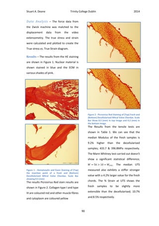
![Stuart A. Deane Trinity College Dublin 2014
91
Discussion – As the data recorded for the
mechanical tests was found to be non-
parametric a Mann Whitney statistical test
was chosen over a traditional t test.
Because of a small data set the median was
chosen to represent the data as the mean
could be influenced by outliers.
The Modulus for the decellularised
chordae was measured as 9.2% lower than
that of the fresh valves with 396.8MPa and
433.7MPa. A Mann Whitney test concludes
that the difference in the data sets is not
significant; . The UTS
was measured as 4.2% lower; 47.2 and
49.2MPa respectively. The % Strain
at failure measured also shows the fresh
valve to be slightly stiffer with values of
8.5% and 10.7%. We can see that the
decellularisation process has reduced the
mechanical properties of the chordae, but
not in any significant way. The rationale for
this is the collagen denaturing reported by
Badylak et al in the use of ionic detergents
[7].
The Physiological conditions
experienced by the chordae are reported
by Rim et al as ranging from 0.3-1.1MPa,
using their computational model [8].
Similarly Sieferts results for the strut
Table 1 – Results of the Uniaxial tensile test data on Mitral Chordae](https://image.slidesharecdn.com/38e6f6e6-808d-47d7-b1bd-3ff471006261-150702142634-lva1-app6892/85/Stuart-Deane-Thesis-102-320.jpg)
![Stuart A. Deane Trinity College Dublin 2014
92
chordae are given as 0.71±0.08MPa. A
study by Liao et al suggests that the thicker
chordae are less strong and more
extensible than thinner chordae [9] and as
we are measuring the effects on the basal
chordae we expect that they will be under
more pressure. Lomholt et al report that
the primary chordae are under 3 times the
tension [10], even so the UTS measured
are far outside of this range. Ritchie et al
report the largest strain experienced
during the cardiac cycle as 4.29% for the
strut chordae. We expect the basal chords
to be less extensible and comparing this
with our typical force/displacement curve
this falls well within the toe region and
thus the elastic region where the chord can
return its original shape without damage.
The reported modulus figures by
Casado are 233MPa with an average area
of .35mm2
[11] and Barber as 132MPa with
an average area of 0.8mm)[12] are smaller
than is measured in this study. Barbers
area is 3.3 times that found in this study
and Casados is 1.45 times. The smallest
area group for mitral chordae reported by
Liao is 0.5-1mm2
which is still twice the
area recorded in this study of
0.24±0.05mm2
. Interestingly if we multiply
these differences by the reported moduli
we find Barbers changes to 435.6MPa and
Casado to 337.9MPa, which are very
similar to the values reported here. A
report by sasaki and odajima suggests that
the modulus of collagen is 430MPa[13] and
as the chordae are largely aligned collagen
this figure also agrees with our study.
These figures suggest that differences in
diameter measurement may have led to
measured modulus differences. Overall we
can conclude that the decellularisation
process has not affected the mechanical
properties of the chordae in a significant
way.
An interesting feature noticeable
more in the image of the decellularised
chordae are the wavy lines running
perpendicular to the length of the chordae,
Figure 2. These lines represent the crimped
collagen structure which is characteristic of
the chordae as described by Liao et al [9].
The crimped structures are sliced in a flat
plane leaving only horizontal lines visible.
As well as this we can see the outer sheath
made of collagen and elastin. Again there
is little visible difference to the collagen
structure and the assumption is that the
decellularisation process made no
substantial change to the collagen
structure.
Cellular material (Stained in Blue)
is abundantly visible in the fresh samples
and appears to be completely removed in
the decellularised samples, indicating that
the decell process has been a success.
Although the chordae image is of the
insertion point and not the mid-chordae as](https://image.slidesharecdn.com/38e6f6e6-808d-47d7-b1bd-3ff471006261-150702142634-lva1-app6892/85/Stuart-Deane-Thesis-103-320.jpg)
![Stuart A. Deane Trinity College Dublin 2014
93
in the decell image Ritchie et al reported
that H&E staining on fresh valves revealed
fibroblasts distributed throughout the
inner and outer layers of the chordae [14]
and so we can still relate a successful
decellularisation based on Figure 1.
Conclusion – We can conclude that the
decellularisation process has been a
success and has not significantly affected
the mechanical or microstructural
properties of the chordae.
Works Cited
1. Devereux, R.B., et al., Mitral valve
prolapse. Circulation, 1976. 54(1):
p. 3-14.
2. Cardiothoracic Surgical Outcome
reports. 2013 [cited 2014 28
March]; Available from:
http://ctsurgery.stanford.edu/pati
ent_care/outcomes_shc.html.
3. Blue Books Online. 2013; Available
from: http://bluebook.scts.org/.
4. Mohty, D., et al., Very Long-Term
Survival and Durability of Mitral
Valve Repair for Mitral Valve
Prolapse. Circulation, 2001.
104(suppl 1): p. I-1-I-7.
5. Acar, C., et al., Homograft
replacement of the mitral valve:
graft selection, technique of
implantation, and results in forty-
three patients. The Journal of
Thoracic and Cardiovascular
Surgery, 1996. 111(2): p. 367-380.
6. Zhou, J., et al., Impact of heart
valve decellularization on 3-D
ultrastructure, immunogenicity and
thrombogenicity. Biomaterials,
2010. 31(9): p. 2549-2554.
7. Badylak, S., Decellularized
Allogeneic and Xenogeneic Tissue
as a Bioscaffold for Regenerative
Medicine: Factors that Influence
the Host Response. Annals of
Biomedical Engineering, 2014: p. 1-
11.
8. Rim, Y., et al., Mitral Valve Repair
Using ePTFE Sutures for Ruptured
Mitral Chordae Tendineae: A
Computational Simulation Study.
Annals of Biomedical Engineering,
2014. 42(1): p. 139-148.
9. Liao, J. and I. Vesely, A structural
basis for the size-related
mechanical properties of mitral
valve chordae tendineae. Journal
of Biomechanics, 2003. 36(8): p.
1125-1133.
10. Lomholt, M., et al., Differential
tension between secondary and
primary mitral chordae in an acute
in-vivo porcine model. The Journal
of heart valve disease, 2002. 11(3):
p. 337-345.
11. Casado, J.A., et al., Determination
of the mechanical properties of
normal and calcified human mitral
chordae tendineae. Journal of the
Mechanical Behavior of Biomedical
Materials, 2012. 13(0): p. 1-13.
12. Barber, J.E., et al., Myxomatous
mitral valve chordae. I: Mechanical
properties. J Heart Valve Dis, 2001.
10(3): p. 320-4.
13. Sasaki, N. and S. Odajima, Stress-
strain curve and young's modulus
of a collagen molecule as
determined by the X-ray diffraction
technique. Journal of
Biomechanics, 1996. 29(5): p. 655-
658.
14. Ritchie, J., J.N. Warnock, and A.P.
Yoganathan, Structural
Characterization of the Chordae
Tendineae in Native Porcine Mitral
Valves. The Annals of Thoracic
Surgery, 2005. 80(1): p. 189-197.](https://image.slidesharecdn.com/38e6f6e6-808d-47d7-b1bd-3ff471006261-150702142634-lva1-app6892/85/Stuart-Deane-Thesis-104-320.jpg)
![Stuart A. Deane Trinity College Dublin 2014
94
Appendix B - Ethical Issues
Introduction
This project is based around developing an effective treatment for
severe degenerative and progressive mitral valve failure. It is important to
look at both the short and long term effects of the research and the implications it may have
for society. In the short term how are tests being carried out and how is tissue being sourced
and resources allocated, in the long term is this treatment more effective than existing
treatments and if the device were to make it to market what would are the potential positive
and detrimental effects possible.
Experimental Stage
Safety Standards
All testing is being carried out under the strictest laboratory safety standards. The
most relevant dealing with personal safety is the European Directive 98/391/EEC whose basic
principle is risk prevention. There are many supplemental directives which support this
document covering chemical,biological, explosive ergonomic and general hazards Some of the
most appropriate being the IEC 61010 dedicated to equipment safety, BS EN 13150:2001 on
workbenches for laboratories, IEC 61010 on Equipment safety and EN IS726:2011 on Building
ventilation [1]. As all of the practical experiments necessary for this phase of testing are basic
and well established the set of standards outlined above give adequate safety coverage.
Tissue Sourcing
It is important to look at the issue surrounding the ethical sourcing of the animal tissue
for testing. At this early stage no live animal testing will take place. A number of studies are
being carried out on porcine heart sections sourced from a local butcher. Sourcing the tissue in
this manner ensures that the animals were killed in such a way as to avoid unnecessary
suffering in accordance with European Directive 93/119/EC. As well as this, sourcing tissue in
this way ensures that all reasonable steps to ensure tissue safety and hygiene meet the
highest standards reasonably available as regulated by the Food safety authority of Ireland [2].](https://image.slidesharecdn.com/38e6f6e6-808d-47d7-b1bd-3ff471006261-150702142634-lva1-app6892/85/Stuart-Deane-Thesis-105-320.jpg)
![Stuart A. Deane Trinity College Dublin 2014
95
Data Analysis and Study Limitations
An essential aspect of any research project is the accurate and unbiased reporting of
all data collected. It is a requirement of the educational institution and or publishing body that
all data is represented accurately and is the product of the individuals own work. Falsification
of results although forbidden can also have detrimental effects on the field of research as
future funding allocation may be wrongly based on them. As well as this a device based on
false results has the potential to cause massive direct damage to patients and clinicians when
brought to market. There are also ethical issues to be considered in the publication of results.
A summary of ethical issues in scientific publication is given by Anil K Jain [3]. In this article
they summarise the main points of Duplicate submission, falsification and Plagiarism.
In this experiment data obtained falls under several criteria. Results come primarily
from histological and mechanical tests. The issue with histological results is that they can be
open to interpretation. The images obtained are examined only by eye and this can lead to
individual opinions differing. This is avoided by examination from a number of researchers and
more experienced researchers to minimise the potential for bias. It is also important that
histological data is displayed in a clear format so as not to influence opinion. As well as this the
results from this study are compared to controls which are treated to similar conditions. It is
difficult to compare various studies as the origin, age, storage and testing conditions the tissue
is subject to can affect the outcome of tests. Measuring the difference against a control is a
more common defined method. The inaccuracy here can be compounded by a mistreatment
which is applied to both the control and test subject although by only measuring the
difference and strictly following standard test procedures this error can be minimised.
The design of the study is also significant in that it must be streamline in order not to
waste either time or funds allocated. As can be seen in the research proposal a timeline for
the study has been arranged. Adjacent to this a thorough review of literature to establish the
most effective test methods was conducted prior to testing.
Fund Allocation
The study is partly funded by the Higher Education Authority whose role is the
statutory planning and policy development body for higher education and research in Ireland.
This body has no conflict of interest which might bias the results published.](https://image.slidesharecdn.com/38e6f6e6-808d-47d7-b1bd-3ff471006261-150702142634-lva1-app6892/85/Stuart-Deane-Thesis-106-320.jpg)
![Stuart A. Deane Trinity College Dublin 2014
96
Importance of the Study
It is essential to assess the importance of the research and to understand whether
funds could be allocated in a more productive way. A mitral valve replacement is considered
only if a repair is not amenable. As shown in Figure 1 [4] the mortality rates for replacement
are much higher than that for repair. This suggests that patients who are recommended for
valve replacement have a much higher chance of morbidity and mortality.
With the number of people suffering from mitral valve disease increasing significantly
due to comorbidities such as obesity, research into this area will become more significant. As
shown in the introduction to my thesis the number of mitral valve replacements in the U.S.
alone could conservatively approximate 21,000 every year. These patients are receiving a less
satisfactory form of treatment and so research into an effective alternative is critical. It is
expected that the new technique will have the potential to exceed current techniques due to
the combination of a simplified surgical procedure, longer lifetime, viability and availability. As
well as this the individual parts of the research, additional constructs, decellularisation and
recellularisation viability are in themselves useful.
Implications for Society
More recently morbidity and disability in the elderly are declining and becoming
compressed into a shorter duration of time before death. One way of looking at this is that
new medical technology is recognised to lengthen the survival of those with disabling
conditions, through diagnostics and treatment, and on the other hand that declining mortality
from fatal diseases leads to a shift in the distribution of causes of disability from fatal to more
(A) (B)
Figure 1 - Mortality (%) for outcomes of valve repair (A) and valve replacement (B) (blue books online)](https://image.slidesharecdn.com/38e6f6e6-808d-47d7-b1bd-3ff471006261-150702142634-lva1-app6892/85/Stuart-Deane-Thesis-107-320.jpg)
![Stuart A. Deane Trinity College Dublin 2014
97
chronic illnesses associated with aging. These areas can then be attributed to the increasing
burden placed on developed societies to support their ever increasing elderly population. With
an increasing elderly population being treated for multiple illnesses and possibly retaining a
number of chronic illnesses, the cost increases will be large. “the nearly 23 million Americans
older than the age of 65 currently represent 11% of the population, yet they account for close
to 30% of the $160 billion spent annually on health care” [5]. And so it seems that although
the diagnosis and treatment of many serious conditions has improved due to medical devices,
statistically our elderly population is less healthy than ever, but somewhat paradoxically are
living longer. All of this puts a bigger strain on society to provide more services to retain
quality of life. Every person in the developed world has the right to adequate healthcare and
whether it is sustainable or not this will continue for some time to come.
The next issue to consider is who could afford to pay for the device if it were to go to
market. Ideally the device could be targeted at pediatrics as well as the elderly. Younger
patients have shown advanced calcification and rapid early failure of Cryopreserved implants
[6] and it is hoped that the developed device would better cater to their needs due to its
recellularisation viability. It has been shown that younger patients are more likely to present
with rheumatic heart disease in less developed countries whereas the increase in elderly
population means that most cases in fully developed countries will be due to degenerative
diseases [7]. It will be important to consider these presentations when conducting clinical
trials and to keep the cost of the device at a level where it can still be accessed by all in need
patients.
Future work
If the projected development of this research into a commercial product were to
advance this would necessitate animal testing and human clinical testing to validate efficacy
and safety of the product. The animal testing will have to be carried out under the European
Directive 2010/63/EU which covers the protection of animals used for scientific purposes [8].
As well as this researchers are required to consider the principles of three Rs, to Replace,
Reduce and refine the use of animals.
It is also suggested that commercialisation may affect the study and results as a
conflict of interest may occur. It will be crucial to implement a system which promotes
objectivity, honesty, respect for research participants and social responsibility. Presently no
financial gain is expected for either positive or negative results and so these ideals are not
affected.](https://image.slidesharecdn.com/38e6f6e6-808d-47d7-b1bd-3ff471006261-150702142634-lva1-app6892/85/Stuart-Deane-Thesis-108-320.jpg)
![Stuart A. Deane Trinity College Dublin 2014
98
Conclusion
We have discussed the major ethical issues likely to be encountered whilst
undertaking this research project. From the Issues of sourcing and working with tissue in a
laboratory setting to the considerations which must be taken into account if the device were
to be commercialised. These issues must be an integral part of the study design in order to
ensure ethical decency.
Works Cited
1. OSHA. Checklist for the prevention of accidents in laboraties. E-Facts; Available from:
http://www.osha.mddsz.gov.si/resources/files/pdf/E-Fact_20_-
_Checklist_for_the_prevention_of_accidents_in_laboratories.pdf.
2. FSAI. Requirments for SLaughterhouses. 13/3/2009; Available from:
https://www.fsai.ie/legislation/food_legislation/fresh_meat/requirements_for_slaugh
terhouses.html.
3. Jain, A.K., Ethical issues in scientific publication. Indian J Orthop, 2010. 44(3): p. 235-7.
4. Blue Books Online. 2013; Available from: http://bluebook.scts.org/.
5. Ouslander, J.G. and J.C. Beck, Defining the Health Problems of the Elderly. Annual
Review of Public Health, 1982. 3(1): p. 55-83.
6. Simon, P., et al., Early failure of the tissue engineered porcine heart valve
SYNERGRAFT® in pediatric patients. European Journal of Cardio-Thoracic Surgery,
2003. 23(6): p. 1002-1006.
7. Vahanian, A., et al., Guidelines on the management of valvular heart disease: The Task
Force on the Management of Valvular Heart Disease of the European Society of
Cardiology. European Heart Journal, 2007. 28(2): p. 230-268.
8. Commission, E. Animals used for scientific purposes. 2014 [cited 2014 18th May];
Available from:
http://ec.europa.eu/environment/chemicals/lab_animals/home_en.htm.](https://image.slidesharecdn.com/38e6f6e6-808d-47d7-b1bd-3ff471006261-150702142634-lva1-app6892/85/Stuart-Deane-Thesis-109-320.jpg)
![Stuart A. Deane Trinity College Dublin 2014
99
Appendix C - Business and Entrepreneurship
Introduction
It is important to investigate the possible impact of a technology in
the market place. In the medical device industry a product which does not
represent a significant profit margin will not be considered feasible as the
resources necessary to bring it to market are substantial. The heart valve
replacement market is forecast to increase and emerging technologies with serious market
potential will become takeover targets for larger companies. It is important to recognise which
pieces of the developed technologies are desirable and what can be protected in order to
maximise business potential. The steps necessary to accomplish market prospects include
preclinical testing to attract significant outside investment which can move the project
forward into IP and regulatory approval.
Market Analysis
The Global heart valve market represents a significant opportunity for emerging
technologies. There have been many market analysis’ carried out predicting growth of the
sector. Forecasts range from an expected Global market for heart valve devices of $1.5[1] to
$1.7[2] billion in the year 2015. In another analysis The US market alone is forecast to reach
$1.73 billion in 2015 [3]. The European market for heart valve repair and replacement
products is forecast to reach an estimated $1.37 Billion in the same year [4]. Although these
forecasts do vary significantly they all predict huge growth from 7-18.3% annually [2, 3].This
predicted growth will attract small manufacturers with specific technologies. The most
influential companies in the market are Edwards, St. Jude Medical and Medtronic, who control
approximately 70% of the overall market share [2] and the market dynamics suggest that
smaller manufacturers with market potential will become tempting takeover targets for the
larger corporations.
The primary reasons given for this growth are an increasing population raising rates of
congenital heart problems and a rapidly growing elderly population with age related valve
degeneration. As these trends are recognised to continue to increase, this market will
continue to grow.
Existing Products
There are a number of products available which represent direct competition to a
bioengineered decellularised xenograft for mitral valve replacement. These devices fall into](https://image.slidesharecdn.com/38e6f6e6-808d-47d7-b1bd-3ff471006261-150702142634-lva1-app6892/85/Stuart-Deane-Thesis-110-320.jpg)
![Stuart A. Deane Trinity College Dublin 2014
100
the following categories Mechanical, Bioprosthetic and homograft. The clinical use of
homografts is very limited due to difficult operative techniques and supply of appropriate
donor valves. Studies which report trends in valve replacement type show a growth in use of
bioprosthetics over the traditional mechanical valves [5]. Their conclusions establish that
improved reoperative mortality rates and longer lifetimes without degeneration are the
reasons behind this. For more recent surgical trends we can look at data from the Cleveland
Clinic, Ohio US, which is the US leader in overall valve surgery and mitral valve surgery volume
per institution. In 2011 they carried out 1,286 primary mitral valve operations of which 416
(32%) were replacements [6]. Their data, from 2007-2011, shows a dramatic shift towards the
use of bioprosthetics over mechanical valve replacements; as can be seen in Figure 1.
This shift in valve replacement type is attributed to advancement in fixation
technology in the tissue engineered bioprosthesis. In the past they were considered to
degenerate too quickly, particularly in younger patients, or patients with significant life
expectancy however recent studies have shown significant improvements in possible implant
lifetimes, with a low rate of valve related events at 18 years for patients over 65 [7]. The
Mechanical replacement is also less desirable due to the necessary long term anticoagulation
therapy.
Logically a valve technology which allowed implantation for longer periods without
degeneration, such as our device which has the potential for constructive remodelling, would
be desirable to companies such as those mentioned before and would therefore represent a
probable takeover target.
Patentability
In order for a technology to be patentable it must satisfy a number of criteria; Novelty,
Non-obviousness and usefulness. In this the device would be patentable as a combination of
Figure 1– All Valve replacement, volume and type from the Cleveland Clinic 2007-2011](https://image.slidesharecdn.com/38e6f6e6-808d-47d7-b1bd-3ff471006261-150702142634-lva1-app6892/85/Stuart-Deane-Thesis-111-320.jpg)
![Stuart A. Deane Trinity College Dublin 2014
103
Works Cited
1. Millenium. US Heart Valve Market to Reach $1.5 Billion by 2016. 2012 26th June, 2012
[cited 2014 17th June]; Available from: http://mrg.net/News-and-Events/Press-
Releases/Heart-Valve-Market-062612.aspx.
2. Transparency. Heart Valve Devices Market - Global Industry Size, Share, Trends,
Analysis and Forecasts 2012 - 2018. 2011 [cited 2014 17th June]; Available from:
http://www.transparencymarketresearch.com/heart-valve-devices-market.html.
3. Science, L. U.S. Markets for Heart Valve Repair and Replacement Products. 2010 [cited
2014 17th June]; Available from: https://www.lifescienceintelligence.com/market-
reports-page.php?id=A212.
4. Medtech. European Markets for Heart Valve Repair and Replacement Products. 2012
[cited 2014 17th June]; Available from:
http://www.medtechinsight.com/ReportA261.html.
5. Gammie, J.S., et al., Trends in Mitral Valve Surgery in the United States: Results From
The Society of Thoracic Surgeons Adult Cardiac Database. The Annals of Thoracic
Surgery, 2009. 87(5): p. 1431-1439.
6. Valve Surgery Outcomes. 2011 [cited 2014 march 8th]; Available from:
http://my.clevelandclinic.org/Documents/heart/Outcomes/2011/05-valve-
disease.pdf.
7. Aupart, M.R., et al., Perimount pericardial bioprosthesis for aortic calcified stenosis:
18-year experience with 1133 patients. The Journal of heart valve disease, 2006. 15(6):
p. 768-75; discussion 775-6.](https://image.slidesharecdn.com/38e6f6e6-808d-47d7-b1bd-3ff471006261-150702142634-lva1-app6892/85/Stuart-Deane-Thesis-114-320.jpg)