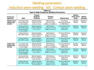
SlideShare a Scribd company logo
High Frequency Welding
Prepared by: - Darshan Shah
Smit Solanki
M.E. Welding Technology (2018-19)
Metallurgical & Materials Engineering Department,
The Maharaja Sayajirao University of Baroda
High Frequency Welding
• High-frequency welding is included in
a group of resistance welding process
variations that use high-frequency
welding current (1kHz to 800kHz) to
concentrate the welding heat at the
desired location.
• The heat produces the coalescence of
metals, and an upsetting force usually
is applied to produce a forged weld.
• High-frequency resistance welding is
an automated process and is not
adaptable to manual welding.
2
High Frequency Welding
• High-frequency resistance welding was developed during the late 1940s and
early 1950s to fill the need for high-integrity butt joints and seam welds in pipe
and tubing.
• But today the process is also used in the manufacture of products such as spiral-
fin boiler tubes, closed roll form shapes, and welded structural beams.
• A wide range of commonly used metals can be welded, including low-carbon and
alloy steels, ferritic and austenitic stainless steels, and many aluminum, copper,
titanium, and nickel alloys.
• HFW is based on two main electrical phenomena
1. Skin effect
2. Proximity effect
3
DC
1. Skin effect
• High-frequency current in metal conductors tends to flow at the surface of the
metal at a relatively shallow depth, which becomes shallower as the electrical
frequency of the power source is increased. This effect is called the skin effect.
• Current penetration depth in a conductor as a function of frequency.
• Due to skin effect heating is concentrated on the surface of the conductor.
Where, δ = Current penetration depth
ρ = Resistivity of the conductor
ω = Angular frequency of current
μ = Magnetic permeability of the conductor
4
2. Proximity effect
• When two conductors carrying HF current are placed close to one another, the current
concentrates on the two adjacent surfaces of the conductors. This is called the proximity
effect.
• Two currents flowing in opposite directions on the same material are mutually attracted.
• Due to proximity effect the heating is concentrated on very little part of the surface of the
conductor.
5
Electric Resistance Welded Tubing
(Low Frequency Resistance Welding)
6
High Frequency Induction Welding
7
High Frequency Induction Welding
• The induction coil induces a circumferential current in the tube.
• The high-frequency current flows along the edge of the weld vee due to the
proximity effect, and the edges are resistance heated to a shallow depth due to the
skin effect.
• Vee length usually between 1.5 to 2 tube diameter.
• Vee angle generally is between 3° and 7°.
• The welding speed and power source level are so adjusted that the two edges are
at the welding or forge temperature when they reach the weld point.
• The forge rolls press the hot edges together, applying an upset force to complete
the weld.
• Hot metal containing impurities from the faying surfaces of the joint is squeezed
out of the weld in both directions, inside and outside the tube.
• The upset metal normally is trimmed off flush with the base metal.
• One of the advantage of using HF is that it minimize the number of turns of
induction coil to 1 – 3 turns.
8
Impeder
Inside the
Core
Promotes
Path ADC
Why impeder is needed?
• Due to skin effect the HF current is
flowing from the very thin layer of the
surface.
• So it distinguishes the outside layer and
inside layer of the tube as two different
conductor.
• Here middle layer of the tube acts as a
perfect insulator as no current is passing
through it due to skin effect.
• The purpose of the impeder is to increase
the impedance (inductive reactance or
effective resistance) of the current path
around the inside wall of the workpiece.
This reduces the current that would
otherwise flow around the inside of the
tube and cause an unacceptable loss of
efficiency.
• An impeder is made from a magnetic
material such as ferrite.
9
High Frequency Contact Welding
• The process essentially is the same as
induction welding.
• The major difference is that sliding
contacts are placed on the tube
adjacent to the unwelded edges at the
vee length.
• Generally vee length is shorter than that
used with the induction process
because the pressure rolls are not
inductively heated by the magnetic field
of the induction coil.
• So the sliding contact can be placed
within the confine space.
10
High Frequency Welding
11
Comparison of the Induction and Contact
Welding Process
• Contact welding is a more efficient process than induction welding
because of the shorter vee length and because there are no losses in the
induction coil.
• For the seam welding of large-diameter pipe, the contact process can use as little
as half the power required by the induction process.
• The major disadvantage of the contact process is sliding contact wear.
• The service life of the contact tips decreases with increasing welding power level
so generally it is not operated above 800 kW.
• In contact welding process under some conditions, arcing between the
sliding contacts and the tube can occur. This may cause “arc marks”.
• Arc marks are required to be removed by a subsequent grinding operation.
• Generally induction welding can be used to weld the smaller-diameter
tube sizes, and contact welding can be used to weld the larger-diameters
sizes.
12
Welding Fins to Boiler Tube
• In Circumferential Fin Welding,
the fin is helically wound on
edge around a tube and
simultaneously welded to the
surface of the tube.
• In Longitudinal Fin Welding,
Fins can be welded
longitudinally to a tube on one
or both sides.
• This type of tube is used to
manufacture water walls in
boilers.
• Tube also can be welded to strip
or sheet metal for products
such as solar absorber plates
and freezer.
13
Weld
Weld
Contact Welding of Structural Beams
• Continuous high frequency
contact welding can be
adapted for the fabrication of
structural I-beams, T-beams
and H-beams.
• It is just a slight modification
to the fin welding technique
14
Weld
Seam Welding of Closed Roll Form Shapes
• Contact or induction processes can be
used depending on C/S.
• Lap welds are often made in roll form
components.
• lap joints must be designed with
consideration for the proximity effect,
and the two faying surfaces must be
brought together to form a vee.
• The geometry of the workpiece often
complicates the forge roll design.
15
Projecti
on Seam
Weld
Roll
Formed
Beam
Induction Welding of Pipe Butt Joints
• Closer the proximity conductor
develops a more confined current path.
• If a magnetic core is placed around the
proximity conductor, the current would
be further concentrated and heating
would take place directly below the
proximity conductor.
• High-frequency current in the coil
induces a circulating current
concentrated in the area of the pipe
butt joint, which is heated very rapidly.
• When the metal reaches welding
temperature, upset force is applied to
produce a forge weld.
16
Contact Welding of Finite-Length Plate Butt
Joints
• Same or dissimilar metals
• Can be of different thicknesses
• Low frequencies between 1 kHz and 10 kHz
generally are used.
• The current is introduced at each end of the
joint by small contacts and is confined to the
area of the joint by a proximity conductor.
• Magnetic core is used to assist in narrowing
the current path.
• When the joint reaches the welding
temperature, a forging force is applied and
the hot metal is upset.
• Welds of this type can be made at rates up to
1000 joints per hour.
17
18
Welding parameters
Induction seem welding V/S Contact seem welding
High frequency welding parameters for
induction welding process
19
Welding Equipments
• Equipment for high-frequency resistance welding includes
1. Power source (usually a solid-state inverter type)
2. Induction coils
3. Contacts
4. Impeders
5. Control devices
6. Mechanical equipment for
preparing and aligning
the workpieces.
20
Power source
• The predominant power source in modern installations of high-
frequency welding equipment is the solid-state inverter power source.
• These units provide welding output power ranging from 50 kW to 1800
kW and operate at frequencies from 80 kHz to 800 kHz.
• Solid-state power sources are smaller in size than traditional vacuum-
tube units and typically demonstrate efficiencies over 80%, while
vacuum-tube units operate at efficiencies between 50% and 65%.
• Economically efficient operation results in a significant decrease in
power consumption and cooling-water requirements.
21
Basic Circuit of a Solid-State Inverter Power Source
22
Solid-State Inverter Switching Sequence
23
Induction Coils
• It is generally fabricated from copper tubing, hollow copper bar or copper sheet.
• Normally water cooled
• Highest efficiency is obtained when the induction coil completely surrounds the
workpiece.
• Coil may have one or more turns.
• The strength of the magnetic field reduces rapidly as the distance between the
coil and the workpiece is increased.
• Spacing between the coil and the workpiece ranges from 3 mm for small-
diameter products to up to 25 mm for large-diameter products
24
AWS Welding Handbook
Contacts
• Made of copper alloy or may be
composed of hard metallic or ceramic
particles in a copper or silver matrix.
• Contact tips are hold via mounts.
• Replaceable due to wear.
• Internal and external cooling is required
for the contact tip and mounts.
• Area of contact tip = 0.25 - 1 in2
• Welding current = 500 - 5000 Amps
• Force of the contact tip against the
workpiece ranges between 20 – 200 N
• Service Life
• 1000 feet under very severe conditions
• 3,00,000 feet if circumstances are
optimal
25
Impeders
26
• The primary function of an impeder is to increase
the impedance around the inside circumference
of the tube, thus diverting more energy into the
weld “vee”.
• An impeder is made from a magnetic material
such as ferrite.
• The impeder must be cooled to prevent its
temperature from rising above its Curie
temperature, where it becomes nonmagnetic.
(For ferrite, it is between 170°C and 340°C.)
• The impeder is positioned so that it extends
about 1.5 mm to 3 mm beyond the apex of the
vee and the equivalent of 1 to 2 workpiece
diameters upstream of the induction coil.
Control Devices
• Control Devices maintain proper welding conditions at different mill
speeds.
• Especially to minimize scrap material resulting when the mill is started
and stopped, the weld power can be automatically adjusted as a
function of mill speed by control Devices.
• So it can virtually eliminate any unwelded seam when the mill is stopped
and restarted.
• The system also will reduce scrap.
• Weld temperature control system reads the output of a pyrometer or
analyzes the image obtained by an infrared camera aimed at the weld
vee, and automatically adjusts the welding power to maintain a
constant, preset temperature.
27
Advantages of High-Frequency Welding
• Produce welds with very narrow heat-affected zones (HAZ) so often
postweld heat treatment is eliminated.
• High welding speed and low-power consumption
• Able to weld very thin wall tubes
• A wide range of commonly used metals can be welded.
• Minimize oxidation and discoloration as well as distortion of workpiece
• Flux is almost never used but inert gas shielding is can be used for joining
highly reactive metals such as titanium
• High efficiency
28
Limitations of High-Frequency Welding
• As the equipment operates in the radio frequency range, special care
must be taken to avoid radiation interference in the plant’s vicinity
• Special precautions must be taken to protect the operator and plant
personnel from the hazards of high-frequency current.
• Uneconomical for products required in small quantities
• Need of proper fit-up for the surfaces to be joined
29
Some Products of High-Frequency Welding
30[Reference: Welding Handbook, Volume 2, p.665, AWS]
References
1. AWS Handbook, Volume 3 - Welding Processes, Part 2
2. John Wright , “Principles of high frequency induction tube welding”
3. Ilona Iatcheva, Georgi Gigov, Georgi Kunov, Rumena Stancheva, “Analysis of induction
heating system for high frequency welding,” Facta Universitatis, Ser: Elec. Energ. Vol. 25,
No 3, December 2012, pp. 183 - 191 DOI: 10.2298/FUEE1203183I
4. John Wright , “Optimizing Efficiency in HF Tube Welding Processes”
5. H. HAGA, K. AOKI AND T. SATO, “Welding Phenomena and Welding Mechanisms in High
Frequency Electric Resistance Welding—1st Report,” AWS 60th Annual Meeting held in
Detroit, Michigan, during April 2-6, 1979
6. Yan Pei, “High Frequency Induction Welding & Post-Welding Heat Treatment of Steel
Pipes,” University of Cambridge, June 2011
7. A. SPAHIU, “Experimental study of the induction heating in the manufacturing of
metallic tubes by longitudinal welding process,” U.P.B. Sci. Bull., Series C, Vol. 69, No. 2,
2007
8. OKABE Takatoshi, IIZUKA Yukinori, IGI Satoshi, “High Reliability Technology of the Weld
Zone of High-Frequency Electric Resistance Welding Linepipes,” FE GIHO No. 34 (Aug.
2014), p. 77–83
31
Thank You

More Related Content

What's hot

1- Welding Terminology.ppt
1- Welding Terminology.ppt1- Welding Terminology.ppt
1- Welding Terminology.ppt
AkmalShauqy1
 
Fundamentals of metal forming processes
Fundamentals of metal forming processesFundamentals of metal forming processes
Fundamentals of metal forming processes
Naman Dave
 
SOLIDIFICATION OF CASTING
SOLIDIFICATION OF CASTINGSOLIDIFICATION OF CASTING
SOLIDIFICATION OF CASTING
Vivek Tyagi
 
Surface Treatment
Surface TreatmentSurface Treatment
Surface Treatment
Mohamed Assem
 
EXPLOSION / EXPLOSIVE WELDING
EXPLOSION / EXPLOSIVE WELDINGEXPLOSION / EXPLOSIVE WELDING
EXPLOSION / EXPLOSIVE WELDING
Souvik Roy
 
HOT CRACKS AND COLD CRACKS (Welding)
HOT CRACKS AND COLD CRACKS (Welding)HOT CRACKS AND COLD CRACKS (Welding)
HOT CRACKS AND COLD CRACKS (Welding)
Melwin Dmello
 
ADVANCE WELDING TECHNOLOGY
ADVANCE WELDING TECHNOLOGY ADVANCE WELDING TECHNOLOGY
ADVANCE WELDING TECHNOLOGY
Ravi Vishwakarma
 
Welding process
Welding processWelding process
Welding process
Gulfam Hussain
 
Heat affected zone
Heat affected zoneHeat affected zone
Heat affected zone
jay prakash
 
Steel and effect of alloying elements
Steel and effect of alloying elementsSteel and effect of alloying elements
Steel and effect of alloying elements
temkin abdlkader
 
Centrifugal casting
Centrifugal castingCentrifugal casting
Centrifugal casting
Abdullah Tusar
 
Wis5 weldability n.ppt 1 11
Wis5 weldability n.ppt 1 11Wis5 weldability n.ppt 1 11
Wis5 weldability n.ppt 1 11
Thang Do Minh
 
4.patterns
4.patterns4.patterns
Carbon dioxide moulding process 1
Carbon dioxide moulding process 1Carbon dioxide moulding process 1
Carbon dioxide moulding process 1
Digvijaysinh Gohil
 
Solidification of metals
Solidification of metalsSolidification of metals
Solidification of metals
Dr.Shagun Agarwal
 
Forming process forging
Forming process forgingForming process forging
Forming process forging
N.Prakasan
 
Metal forming processes
Metal forming processesMetal forming processes
Metal forming processes
Er Deepak Sharma
 
Cast irons
Cast  ironsCast  irons
Cast irons
temkin abdlkader
 
Advanced Welding Technology
Advanced Welding TechnologyAdvanced Welding Technology
Advanced Welding Technology
abhibhavesh
 
casting ppt
casting pptcasting ppt
casting ppt
Tayyab Warraich
 

What's hot (20)

1- Welding Terminology.ppt
1- Welding Terminology.ppt1- Welding Terminology.ppt
1- Welding Terminology.ppt
 
Fundamentals of metal forming processes
Fundamentals of metal forming processesFundamentals of metal forming processes
Fundamentals of metal forming processes
 
SOLIDIFICATION OF CASTING
SOLIDIFICATION OF CASTINGSOLIDIFICATION OF CASTING
SOLIDIFICATION OF CASTING
 
Surface Treatment
Surface TreatmentSurface Treatment
Surface Treatment
 
EXPLOSION / EXPLOSIVE WELDING
EXPLOSION / EXPLOSIVE WELDINGEXPLOSION / EXPLOSIVE WELDING
EXPLOSION / EXPLOSIVE WELDING
 
HOT CRACKS AND COLD CRACKS (Welding)
HOT CRACKS AND COLD CRACKS (Welding)HOT CRACKS AND COLD CRACKS (Welding)
HOT CRACKS AND COLD CRACKS (Welding)
 
ADVANCE WELDING TECHNOLOGY
ADVANCE WELDING TECHNOLOGY ADVANCE WELDING TECHNOLOGY
ADVANCE WELDING TECHNOLOGY
 
Welding process
Welding processWelding process
Welding process
 
Heat affected zone
Heat affected zoneHeat affected zone
Heat affected zone
 
Steel and effect of alloying elements
Steel and effect of alloying elementsSteel and effect of alloying elements
Steel and effect of alloying elements
 
Centrifugal casting
Centrifugal castingCentrifugal casting
Centrifugal casting
 
Wis5 weldability n.ppt 1 11
Wis5 weldability n.ppt 1 11Wis5 weldability n.ppt 1 11
Wis5 weldability n.ppt 1 11
 
4.patterns
4.patterns4.patterns
4.patterns
 
Carbon dioxide moulding process 1
Carbon dioxide moulding process 1Carbon dioxide moulding process 1
Carbon dioxide moulding process 1
 
Solidification of metals
Solidification of metalsSolidification of metals
Solidification of metals
 
Forming process forging
Forming process forgingForming process forging
Forming process forging
 
Metal forming processes
Metal forming processesMetal forming processes
Metal forming processes
 
Cast irons
Cast  ironsCast  irons
Cast irons
 
Advanced Welding Technology
Advanced Welding TechnologyAdvanced Welding Technology
Advanced Welding Technology
 
casting ppt
casting pptcasting ppt
casting ppt
 

Similar to High frequency welding

Types of welding
Types of weldingTypes of welding
Types of welding
Nisarg Amin
 
Welding
WeldingWelding
Welding
WeldingWelding
ME 12A8 - WELDING TECHNOLOGY for industries.pptx
ME 12A8 - WELDING TECHNOLOGY for industries.pptxME 12A8 - WELDING TECHNOLOGY for industries.pptx
ME 12A8 - WELDING TECHNOLOGY for industries.pptx
RamasamyN4
 
Joining processes (welding)
Joining processes (welding)Joining processes (welding)
Joining processes (welding)
9665930613
 
Unit 4 -Special Welding Processes.ppt
Unit 4 -Special Welding Processes.pptUnit 4 -Special Welding Processes.ppt
Unit 4 -Special Welding Processes.ppt
MayurAppaiah
 
Transformer Designing
Transformer Designing Transformer Designing
Transformer Designing
Praveen Sharma
 
Gas Metal Arc Welding (GMAW)
Gas Metal Arc Welding (GMAW)Gas Metal Arc Welding (GMAW)
Gas Metal Arc Welding (GMAW)
saahil kshatriya
 
Welding
WeldingWelding
Welding
arun kumar
 
UNIT 5-Special Welding processwelding.ppt
UNIT 5-Special Welding processwelding.pptUNIT 5-Special Welding processwelding.ppt
UNIT 5-Special Welding processwelding.ppt
Praveen Kumar
 
UNIT 5-Special Welding processmechanical welding.ppt
UNIT 5-Special Welding processmechanical welding.pptUNIT 5-Special Welding processmechanical welding.ppt
UNIT 5-Special Welding processmechanical welding.ppt
Praveen Kumar
 
UNIT 5-Special Welding process mechanical.ppt
UNIT 5-Special Welding process mechanical.pptUNIT 5-Special Welding process mechanical.ppt
UNIT 5-Special Welding process mechanical.ppt
Praveen Kumar
 
Welding 2
Welding  2Welding  2
Welding 2
Jithu John
 
MIG,TIG Welding process
MIG,TIG Welding processMIG,TIG Welding process
MIG,TIG Welding process
sharmaabhi
 
Lecture-2.4.pdf
Lecture-2.4.pdfLecture-2.4.pdf
Lecture-2.4.pdf
BHAVESHRAMTEKKAR2
 
ELECTRO DISCHARGE MACHINING
ELECTRO  DISCHARGE MACHININGELECTRO  DISCHARGE MACHINING
ELECTRO DISCHARGE MACHINING
gautam buddha university
 
As resistance welding converted
As resistance welding convertedAs resistance welding converted
As resistance welding converted
sharmaabhi
 
Welding Processes
Welding ProcessesWelding Processes
Welding Processes
Himanshi Gupta
 
Manufacturing Processes (Arc Welding)
Manufacturing Processes (Arc Welding)Manufacturing Processes (Arc Welding)
Manufacturing Processes (Arc Welding)
Dhrumit Patel
 
Conducting Materials.pptx
Conducting Materials.pptxConducting Materials.pptx
Conducting Materials.pptx
aman400979
 

Similar to High frequency welding (20)

Types of welding
Types of weldingTypes of welding
Types of welding
 
Welding
WeldingWelding
Welding
 
Welding
WeldingWelding
Welding
 
ME 12A8 - WELDING TECHNOLOGY for industries.pptx
ME 12A8 - WELDING TECHNOLOGY for industries.pptxME 12A8 - WELDING TECHNOLOGY for industries.pptx
ME 12A8 - WELDING TECHNOLOGY for industries.pptx
 
Joining processes (welding)
Joining processes (welding)Joining processes (welding)
Joining processes (welding)
 
Unit 4 -Special Welding Processes.ppt
Unit 4 -Special Welding Processes.pptUnit 4 -Special Welding Processes.ppt
Unit 4 -Special Welding Processes.ppt
 
Transformer Designing
Transformer Designing Transformer Designing
Transformer Designing
 
Gas Metal Arc Welding (GMAW)
Gas Metal Arc Welding (GMAW)Gas Metal Arc Welding (GMAW)
Gas Metal Arc Welding (GMAW)
 
Welding
WeldingWelding
Welding
 
UNIT 5-Special Welding processwelding.ppt
UNIT 5-Special Welding processwelding.pptUNIT 5-Special Welding processwelding.ppt
UNIT 5-Special Welding processwelding.ppt
 
UNIT 5-Special Welding processmechanical welding.ppt
UNIT 5-Special Welding processmechanical welding.pptUNIT 5-Special Welding processmechanical welding.ppt
UNIT 5-Special Welding processmechanical welding.ppt
 
UNIT 5-Special Welding process mechanical.ppt
UNIT 5-Special Welding process mechanical.pptUNIT 5-Special Welding process mechanical.ppt
UNIT 5-Special Welding process mechanical.ppt
 
Welding 2
Welding  2Welding  2
Welding 2
 
MIG,TIG Welding process
MIG,TIG Welding processMIG,TIG Welding process
MIG,TIG Welding process
 
Lecture-2.4.pdf
Lecture-2.4.pdfLecture-2.4.pdf
Lecture-2.4.pdf
 
ELECTRO DISCHARGE MACHINING
ELECTRO  DISCHARGE MACHININGELECTRO  DISCHARGE MACHINING
ELECTRO DISCHARGE MACHINING
 
As resistance welding converted
As resistance welding convertedAs resistance welding converted
As resistance welding converted
 
Welding Processes
Welding ProcessesWelding Processes
Welding Processes
 
Manufacturing Processes (Arc Welding)
Manufacturing Processes (Arc Welding)Manufacturing Processes (Arc Welding)
Manufacturing Processes (Arc Welding)
 
Conducting Materials.pptx
Conducting Materials.pptxConducting Materials.pptx
Conducting Materials.pptx
 

Recently uploaded

哪里办理(csu毕业证书)查尔斯特大学毕业证硕士学历原版一模一样
哪里办理(csu毕业证书)查尔斯特大学毕业证硕士学历原版一模一样哪里办理(csu毕业证书)查尔斯特大学毕业证硕士学历原版一模一样
哪里办理(csu毕业证书)查尔斯特大学毕业证硕士学历原版一模一样
insn4465
 
Literature Review Basics and Understanding Reference Management.pptx
Literature Review Basics and Understanding Reference Management.pptxLiterature Review Basics and Understanding Reference Management.pptx
Literature Review Basics and Understanding Reference Management.pptx
Dr Ramhari Poudyal
 
14 Template Contractual Notice - EOT Application
14 Template Contractual Notice - EOT Application14 Template Contractual Notice - EOT Application
14 Template Contractual Notice - EOT Application
SyedAbiiAzazi1
 
Properties Railway Sleepers and Test.pptx
Properties Railway Sleepers and Test.pptxProperties Railway Sleepers and Test.pptx
Properties Railway Sleepers and Test.pptx
MDSABBIROJJAMANPAYEL
 
132/33KV substation case study Presentation
132/33KV substation case study Presentation132/33KV substation case study Presentation
132/33KV substation case study Presentation
kandramariana6
 
DEEP LEARNING FOR SMART GRID INTRUSION DETECTION: A HYBRID CNN-LSTM-BASED MODEL
DEEP LEARNING FOR SMART GRID INTRUSION DETECTION: A HYBRID CNN-LSTM-BASED MODELDEEP LEARNING FOR SMART GRID INTRUSION DETECTION: A HYBRID CNN-LSTM-BASED MODEL
DEEP LEARNING FOR SMART GRID INTRUSION DETECTION: A HYBRID CNN-LSTM-BASED MODEL
gerogepatton
 
New techniques for characterising damage in rock slopes.pdf
New techniques for characterising damage in rock slopes.pdfNew techniques for characterising damage in rock slopes.pdf
New techniques for characterising damage in rock slopes.pdf
wisnuprabawa3
 
5214-1693458878915-Unit 6 2023 to 2024 academic year assignment (AutoRecovere...
5214-1693458878915-Unit 6 2023 to 2024 academic year assignment (AutoRecovere...5214-1693458878915-Unit 6 2023 to 2024 academic year assignment (AutoRecovere...
5214-1693458878915-Unit 6 2023 to 2024 academic year assignment (AutoRecovere...
ihlasbinance2003
 
Harnessing WebAssembly for Real-time Stateless Streaming Pipelines
Harnessing WebAssembly for Real-time Stateless Streaming PipelinesHarnessing WebAssembly for Real-time Stateless Streaming Pipelines
Harnessing WebAssembly for Real-time Stateless Streaming Pipelines
Christina Lin
 
Recycled Concrete Aggregate in Construction Part III
Recycled Concrete Aggregate in Construction Part IIIRecycled Concrete Aggregate in Construction Part III
Recycled Concrete Aggregate in Construction Part III
Aditya Rajan Patra
 
digital fundamental by Thomas L.floydl.pdf
digital fundamental by Thomas L.floydl.pdfdigital fundamental by Thomas L.floydl.pdf
digital fundamental by Thomas L.floydl.pdf
drwaing
 
bank management system in java and mysql report1.pdf
bank management system in java and mysql report1.pdfbank management system in java and mysql report1.pdf
bank management system in java and mysql report1.pdf
Divyam548318
 
spirit beverages ppt without graphics.pptx
spirit beverages ppt without graphics.pptxspirit beverages ppt without graphics.pptx
spirit beverages ppt without graphics.pptx
Madan Karki
 
Iron and Steel Technology Roadmap - Towards more sustainable steelmaking.pdf
Iron and Steel Technology Roadmap - Towards more sustainable steelmaking.pdfIron and Steel Technology Roadmap - Towards more sustainable steelmaking.pdf
Iron and Steel Technology Roadmap - Towards more sustainable steelmaking.pdf
RadiNasr
 
Presentation of IEEE Slovenia CIS (Computational Intelligence Society) Chapte...
Presentation of IEEE Slovenia CIS (Computational Intelligence Society) Chapte...Presentation of IEEE Slovenia CIS (Computational Intelligence Society) Chapte...
Presentation of IEEE Slovenia CIS (Computational Intelligence Society) Chapte...
University of Maribor
 
Low power architecture of logic gates using adiabatic techniques
Low power architecture of logic gates using adiabatic techniquesLow power architecture of logic gates using adiabatic techniques
Low power architecture of logic gates using adiabatic techniques
nooriasukmaningtyas
 
2. Operations Strategy in a Global Environment.ppt
2. Operations Strategy in a Global Environment.ppt2. Operations Strategy in a Global Environment.ppt
2. Operations Strategy in a Global Environment.ppt
PuktoonEngr
 
DfMAy 2024 - key insights and contributions
DfMAy 2024 - key insights and contributionsDfMAy 2024 - key insights and contributions
DfMAy 2024 - key insights and contributions
gestioneergodomus
 
CHINA’S GEO-ECONOMIC OUTREACH IN CENTRAL ASIAN COUNTRIES AND FUTURE PROSPECT
CHINA’S GEO-ECONOMIC OUTREACH IN CENTRAL ASIAN COUNTRIES AND FUTURE PROSPECTCHINA’S GEO-ECONOMIC OUTREACH IN CENTRAL ASIAN COUNTRIES AND FUTURE PROSPECT
CHINA’S GEO-ECONOMIC OUTREACH IN CENTRAL ASIAN COUNTRIES AND FUTURE PROSPECT
jpsjournal1
 
Embedded machine learning-based road conditions and driving behavior monitoring
Embedded machine learning-based road conditions and driving behavior monitoringEmbedded machine learning-based road conditions and driving behavior monitoring
Embedded machine learning-based road conditions and driving behavior monitoring
IJECEIAES
 

Recently uploaded (20)

哪里办理(csu毕业证书)查尔斯特大学毕业证硕士学历原版一模一样
哪里办理(csu毕业证书)查尔斯特大学毕业证硕士学历原版一模一样哪里办理(csu毕业证书)查尔斯特大学毕业证硕士学历原版一模一样
哪里办理(csu毕业证书)查尔斯特大学毕业证硕士学历原版一模一样
 
Literature Review Basics and Understanding Reference Management.pptx
Literature Review Basics and Understanding Reference Management.pptxLiterature Review Basics and Understanding Reference Management.pptx
Literature Review Basics and Understanding Reference Management.pptx
 
14 Template Contractual Notice - EOT Application
14 Template Contractual Notice - EOT Application14 Template Contractual Notice - EOT Application
14 Template Contractual Notice - EOT Application
 
Properties Railway Sleepers and Test.pptx
Properties Railway Sleepers and Test.pptxProperties Railway Sleepers and Test.pptx
Properties Railway Sleepers and Test.pptx
 
132/33KV substation case study Presentation
132/33KV substation case study Presentation132/33KV substation case study Presentation
132/33KV substation case study Presentation
 
DEEP LEARNING FOR SMART GRID INTRUSION DETECTION: A HYBRID CNN-LSTM-BASED MODEL
DEEP LEARNING FOR SMART GRID INTRUSION DETECTION: A HYBRID CNN-LSTM-BASED MODELDEEP LEARNING FOR SMART GRID INTRUSION DETECTION: A HYBRID CNN-LSTM-BASED MODEL
DEEP LEARNING FOR SMART GRID INTRUSION DETECTION: A HYBRID CNN-LSTM-BASED MODEL
 
New techniques for characterising damage in rock slopes.pdf
New techniques for characterising damage in rock slopes.pdfNew techniques for characterising damage in rock slopes.pdf
New techniques for characterising damage in rock slopes.pdf
 
5214-1693458878915-Unit 6 2023 to 2024 academic year assignment (AutoRecovere...
5214-1693458878915-Unit 6 2023 to 2024 academic year assignment (AutoRecovere...5214-1693458878915-Unit 6 2023 to 2024 academic year assignment (AutoRecovere...
5214-1693458878915-Unit 6 2023 to 2024 academic year assignment (AutoRecovere...
 
Harnessing WebAssembly for Real-time Stateless Streaming Pipelines
Harnessing WebAssembly for Real-time Stateless Streaming PipelinesHarnessing WebAssembly for Real-time Stateless Streaming Pipelines
Harnessing WebAssembly for Real-time Stateless Streaming Pipelines
 
Recycled Concrete Aggregate in Construction Part III
Recycled Concrete Aggregate in Construction Part IIIRecycled Concrete Aggregate in Construction Part III
Recycled Concrete Aggregate in Construction Part III
 
digital fundamental by Thomas L.floydl.pdf
digital fundamental by Thomas L.floydl.pdfdigital fundamental by Thomas L.floydl.pdf
digital fundamental by Thomas L.floydl.pdf
 
bank management system in java and mysql report1.pdf
bank management system in java and mysql report1.pdfbank management system in java and mysql report1.pdf
bank management system in java and mysql report1.pdf
 
spirit beverages ppt without graphics.pptx
spirit beverages ppt without graphics.pptxspirit beverages ppt without graphics.pptx
spirit beverages ppt without graphics.pptx
 
Iron and Steel Technology Roadmap - Towards more sustainable steelmaking.pdf
Iron and Steel Technology Roadmap - Towards more sustainable steelmaking.pdfIron and Steel Technology Roadmap - Towards more sustainable steelmaking.pdf
Iron and Steel Technology Roadmap - Towards more sustainable steelmaking.pdf
 
Presentation of IEEE Slovenia CIS (Computational Intelligence Society) Chapte...
Presentation of IEEE Slovenia CIS (Computational Intelligence Society) Chapte...Presentation of IEEE Slovenia CIS (Computational Intelligence Society) Chapte...
Presentation of IEEE Slovenia CIS (Computational Intelligence Society) Chapte...
 
Low power architecture of logic gates using adiabatic techniques
Low power architecture of logic gates using adiabatic techniquesLow power architecture of logic gates using adiabatic techniques
Low power architecture of logic gates using adiabatic techniques
 
2. Operations Strategy in a Global Environment.ppt
2. Operations Strategy in a Global Environment.ppt2. Operations Strategy in a Global Environment.ppt
2. Operations Strategy in a Global Environment.ppt
 
DfMAy 2024 - key insights and contributions
DfMAy 2024 - key insights and contributionsDfMAy 2024 - key insights and contributions
DfMAy 2024 - key insights and contributions
 
CHINA’S GEO-ECONOMIC OUTREACH IN CENTRAL ASIAN COUNTRIES AND FUTURE PROSPECT
CHINA’S GEO-ECONOMIC OUTREACH IN CENTRAL ASIAN COUNTRIES AND FUTURE PROSPECTCHINA’S GEO-ECONOMIC OUTREACH IN CENTRAL ASIAN COUNTRIES AND FUTURE PROSPECT
CHINA’S GEO-ECONOMIC OUTREACH IN CENTRAL ASIAN COUNTRIES AND FUTURE PROSPECT
 
Embedded machine learning-based road conditions and driving behavior monitoring
Embedded machine learning-based road conditions and driving behavior monitoringEmbedded machine learning-based road conditions and driving behavior monitoring
Embedded machine learning-based road conditions and driving behavior monitoring
 

High frequency welding

  • 1. High Frequency Welding Prepared by: - Darshan Shah Smit Solanki M.E. Welding Technology (2018-19) Metallurgical & Materials Engineering Department, The Maharaja Sayajirao University of Baroda
  • 2. High Frequency Welding • High-frequency welding is included in a group of resistance welding process variations that use high-frequency welding current (1kHz to 800kHz) to concentrate the welding heat at the desired location. • The heat produces the coalescence of metals, and an upsetting force usually is applied to produce a forged weld. • High-frequency resistance welding is an automated process and is not adaptable to manual welding. 2
  • 3. High Frequency Welding • High-frequency resistance welding was developed during the late 1940s and early 1950s to fill the need for high-integrity butt joints and seam welds in pipe and tubing. • But today the process is also used in the manufacture of products such as spiral- fin boiler tubes, closed roll form shapes, and welded structural beams. • A wide range of commonly used metals can be welded, including low-carbon and alloy steels, ferritic and austenitic stainless steels, and many aluminum, copper, titanium, and nickel alloys. • HFW is based on two main electrical phenomena 1. Skin effect 2. Proximity effect 3
  • 4. DC 1. Skin effect • High-frequency current in metal conductors tends to flow at the surface of the metal at a relatively shallow depth, which becomes shallower as the electrical frequency of the power source is increased. This effect is called the skin effect. • Current penetration depth in a conductor as a function of frequency. • Due to skin effect heating is concentrated on the surface of the conductor. Where, δ = Current penetration depth ρ = Resistivity of the conductor ω = Angular frequency of current μ = Magnetic permeability of the conductor 4
  • 5. 2. Proximity effect • When two conductors carrying HF current are placed close to one another, the current concentrates on the two adjacent surfaces of the conductors. This is called the proximity effect. • Two currents flowing in opposite directions on the same material are mutually attracted. • Due to proximity effect the heating is concentrated on very little part of the surface of the conductor. 5
  • 6. Electric Resistance Welded Tubing (Low Frequency Resistance Welding) 6
  • 8. High Frequency Induction Welding • The induction coil induces a circumferential current in the tube. • The high-frequency current flows along the edge of the weld vee due to the proximity effect, and the edges are resistance heated to a shallow depth due to the skin effect. • Vee length usually between 1.5 to 2 tube diameter. • Vee angle generally is between 3° and 7°. • The welding speed and power source level are so adjusted that the two edges are at the welding or forge temperature when they reach the weld point. • The forge rolls press the hot edges together, applying an upset force to complete the weld. • Hot metal containing impurities from the faying surfaces of the joint is squeezed out of the weld in both directions, inside and outside the tube. • The upset metal normally is trimmed off flush with the base metal. • One of the advantage of using HF is that it minimize the number of turns of induction coil to 1 – 3 turns. 8
  • 9. Impeder Inside the Core Promotes Path ADC Why impeder is needed? • Due to skin effect the HF current is flowing from the very thin layer of the surface. • So it distinguishes the outside layer and inside layer of the tube as two different conductor. • Here middle layer of the tube acts as a perfect insulator as no current is passing through it due to skin effect. • The purpose of the impeder is to increase the impedance (inductive reactance or effective resistance) of the current path around the inside wall of the workpiece. This reduces the current that would otherwise flow around the inside of the tube and cause an unacceptable loss of efficiency. • An impeder is made from a magnetic material such as ferrite. 9
  • 10. High Frequency Contact Welding • The process essentially is the same as induction welding. • The major difference is that sliding contacts are placed on the tube adjacent to the unwelded edges at the vee length. • Generally vee length is shorter than that used with the induction process because the pressure rolls are not inductively heated by the magnetic field of the induction coil. • So the sliding contact can be placed within the confine space. 10
  • 12. Comparison of the Induction and Contact Welding Process • Contact welding is a more efficient process than induction welding because of the shorter vee length and because there are no losses in the induction coil. • For the seam welding of large-diameter pipe, the contact process can use as little as half the power required by the induction process. • The major disadvantage of the contact process is sliding contact wear. • The service life of the contact tips decreases with increasing welding power level so generally it is not operated above 800 kW. • In contact welding process under some conditions, arcing between the sliding contacts and the tube can occur. This may cause “arc marks”. • Arc marks are required to be removed by a subsequent grinding operation. • Generally induction welding can be used to weld the smaller-diameter tube sizes, and contact welding can be used to weld the larger-diameters sizes. 12
  • 13. Welding Fins to Boiler Tube • In Circumferential Fin Welding, the fin is helically wound on edge around a tube and simultaneously welded to the surface of the tube. • In Longitudinal Fin Welding, Fins can be welded longitudinally to a tube on one or both sides. • This type of tube is used to manufacture water walls in boilers. • Tube also can be welded to strip or sheet metal for products such as solar absorber plates and freezer. 13 Weld Weld
  • 14. Contact Welding of Structural Beams • Continuous high frequency contact welding can be adapted for the fabrication of structural I-beams, T-beams and H-beams. • It is just a slight modification to the fin welding technique 14 Weld
  • 15. Seam Welding of Closed Roll Form Shapes • Contact or induction processes can be used depending on C/S. • Lap welds are often made in roll form components. • lap joints must be designed with consideration for the proximity effect, and the two faying surfaces must be brought together to form a vee. • The geometry of the workpiece often complicates the forge roll design. 15 Projecti on Seam Weld Roll Formed Beam
  • 16. Induction Welding of Pipe Butt Joints • Closer the proximity conductor develops a more confined current path. • If a magnetic core is placed around the proximity conductor, the current would be further concentrated and heating would take place directly below the proximity conductor. • High-frequency current in the coil induces a circulating current concentrated in the area of the pipe butt joint, which is heated very rapidly. • When the metal reaches welding temperature, upset force is applied to produce a forge weld. 16
  • 17. Contact Welding of Finite-Length Plate Butt Joints • Same or dissimilar metals • Can be of different thicknesses • Low frequencies between 1 kHz and 10 kHz generally are used. • The current is introduced at each end of the joint by small contacts and is confined to the area of the joint by a proximity conductor. • Magnetic core is used to assist in narrowing the current path. • When the joint reaches the welding temperature, a forging force is applied and the hot metal is upset. • Welds of this type can be made at rates up to 1000 joints per hour. 17
  • 18. 18 Welding parameters Induction seem welding V/S Contact seem welding
  • 19. High frequency welding parameters for induction welding process 19
  • 20. Welding Equipments • Equipment for high-frequency resistance welding includes 1. Power source (usually a solid-state inverter type) 2. Induction coils 3. Contacts 4. Impeders 5. Control devices 6. Mechanical equipment for preparing and aligning the workpieces. 20
  • 21. Power source • The predominant power source in modern installations of high- frequency welding equipment is the solid-state inverter power source. • These units provide welding output power ranging from 50 kW to 1800 kW and operate at frequencies from 80 kHz to 800 kHz. • Solid-state power sources are smaller in size than traditional vacuum- tube units and typically demonstrate efficiencies over 80%, while vacuum-tube units operate at efficiencies between 50% and 65%. • Economically efficient operation results in a significant decrease in power consumption and cooling-water requirements. 21
  • 22. Basic Circuit of a Solid-State Inverter Power Source 22
  • 24. Induction Coils • It is generally fabricated from copper tubing, hollow copper bar or copper sheet. • Normally water cooled • Highest efficiency is obtained when the induction coil completely surrounds the workpiece. • Coil may have one or more turns. • The strength of the magnetic field reduces rapidly as the distance between the coil and the workpiece is increased. • Spacing between the coil and the workpiece ranges from 3 mm for small- diameter products to up to 25 mm for large-diameter products 24
  • 25. AWS Welding Handbook Contacts • Made of copper alloy or may be composed of hard metallic or ceramic particles in a copper or silver matrix. • Contact tips are hold via mounts. • Replaceable due to wear. • Internal and external cooling is required for the contact tip and mounts. • Area of contact tip = 0.25 - 1 in2 • Welding current = 500 - 5000 Amps • Force of the contact tip against the workpiece ranges between 20 – 200 N • Service Life • 1000 feet under very severe conditions • 3,00,000 feet if circumstances are optimal 25
  • 26. Impeders 26 • The primary function of an impeder is to increase the impedance around the inside circumference of the tube, thus diverting more energy into the weld “vee”. • An impeder is made from a magnetic material such as ferrite. • The impeder must be cooled to prevent its temperature from rising above its Curie temperature, where it becomes nonmagnetic. (For ferrite, it is between 170°C and 340°C.) • The impeder is positioned so that it extends about 1.5 mm to 3 mm beyond the apex of the vee and the equivalent of 1 to 2 workpiece diameters upstream of the induction coil.
  • 27. Control Devices • Control Devices maintain proper welding conditions at different mill speeds. • Especially to minimize scrap material resulting when the mill is started and stopped, the weld power can be automatically adjusted as a function of mill speed by control Devices. • So it can virtually eliminate any unwelded seam when the mill is stopped and restarted. • The system also will reduce scrap. • Weld temperature control system reads the output of a pyrometer or analyzes the image obtained by an infrared camera aimed at the weld vee, and automatically adjusts the welding power to maintain a constant, preset temperature. 27
  • 28. Advantages of High-Frequency Welding • Produce welds with very narrow heat-affected zones (HAZ) so often postweld heat treatment is eliminated. • High welding speed and low-power consumption • Able to weld very thin wall tubes • A wide range of commonly used metals can be welded. • Minimize oxidation and discoloration as well as distortion of workpiece • Flux is almost never used but inert gas shielding is can be used for joining highly reactive metals such as titanium • High efficiency 28
  • 29. Limitations of High-Frequency Welding • As the equipment operates in the radio frequency range, special care must be taken to avoid radiation interference in the plant’s vicinity • Special precautions must be taken to protect the operator and plant personnel from the hazards of high-frequency current. • Uneconomical for products required in small quantities • Need of proper fit-up for the surfaces to be joined 29
  • 30. Some Products of High-Frequency Welding 30[Reference: Welding Handbook, Volume 2, p.665, AWS]
  • 31. References 1. AWS Handbook, Volume 3 - Welding Processes, Part 2 2. John Wright , “Principles of high frequency induction tube welding” 3. Ilona Iatcheva, Georgi Gigov, Georgi Kunov, Rumena Stancheva, “Analysis of induction heating system for high frequency welding,” Facta Universitatis, Ser: Elec. Energ. Vol. 25, No 3, December 2012, pp. 183 - 191 DOI: 10.2298/FUEE1203183I 4. John Wright , “Optimizing Efficiency in HF Tube Welding Processes” 5. H. HAGA, K. AOKI AND T. SATO, “Welding Phenomena and Welding Mechanisms in High Frequency Electric Resistance Welding—1st Report,” AWS 60th Annual Meeting held in Detroit, Michigan, during April 2-6, 1979 6. Yan Pei, “High Frequency Induction Welding & Post-Welding Heat Treatment of Steel Pipes,” University of Cambridge, June 2011 7. A. SPAHIU, “Experimental study of the induction heating in the manufacturing of metallic tubes by longitudinal welding process,” U.P.B. Sci. Bull., Series C, Vol. 69, No. 2, 2007 8. OKABE Takatoshi, IIZUKA Yukinori, IGI Satoshi, “High Reliability Technology of the Weld Zone of High-Frequency Electric Resistance Welding Linepipes,” FE GIHO No. 34 (Aug. 2014), p. 77–83 31