Download to read offline


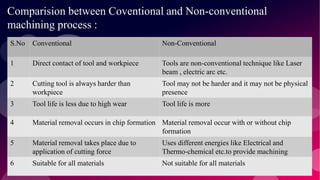
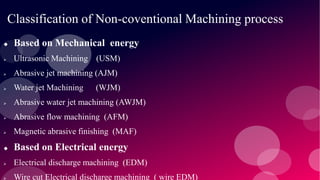

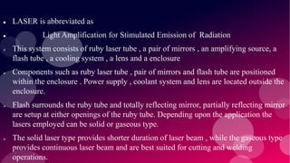


The document provides information on various non-conventional machining processes. It begins with defining machining and distinguishing between conventional and non-conventional processes. Key non-conventional processes discussed include ultrasonic machining, electrical discharge machining (EDM), laser beam machining, and electrochemical grinding. Ultrasonic machining uses abrasive particles and high frequency vibrations to remove material. EDM uses electric sparks to erode material by thermal melting/vaporization. Laser beam machining focuses an intense laser to melt/vaporize workpieces. Electrochemical grinding combines material removal by abrasion and electrochemical deposition of an oxide film.


![Electrical discharge machining [EDM]](https://cdn.slidesharecdn.com/ss_thumbnails/electricaldischargemachiningedm-170803232011-thumbnail.jpg?width=640&height=640&fit=bounds)


