Downloaded 114 times
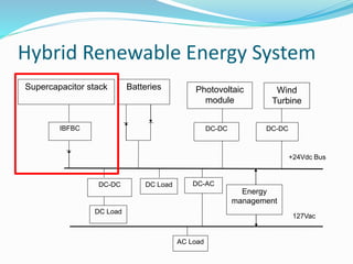
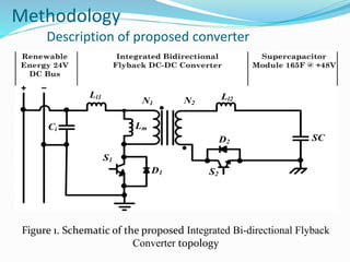
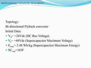
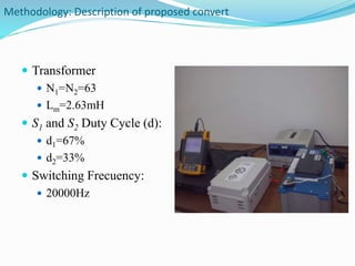
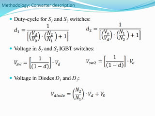
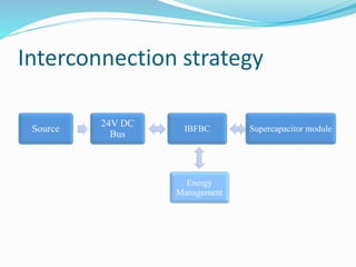
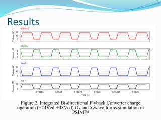
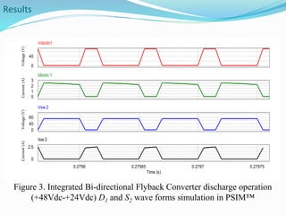
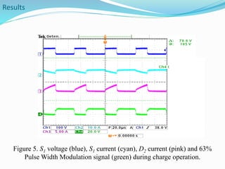
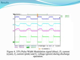
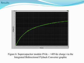
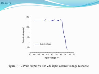
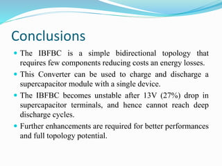

The document describes a study of an Integrated Bi-directional Flyback Converter (IBFBC) for interfacing renewable energy sources, energy storage, and loads. The IBFBC allows both charging and discharging of a supercapacitor module from a 24V DC bus. Simulation results show the converter can charge the supercapacitor from 0V to 48V and regulate the output voltage. However, the converter becomes unstable after a 27% drop in the supercapacitor voltage, limiting its ability to fully discharge the storage. Further improvements are needed to enhance the converter's performance.


![2100069076 [Autosaved].pptx jnunuuhhihihhi](https://cdn.slidesharecdn.com/ss_thumbnails/2100069076autosaved-251230044957-c15eebae-thumbnail.jpg?width=640&height=640&fit=bounds)