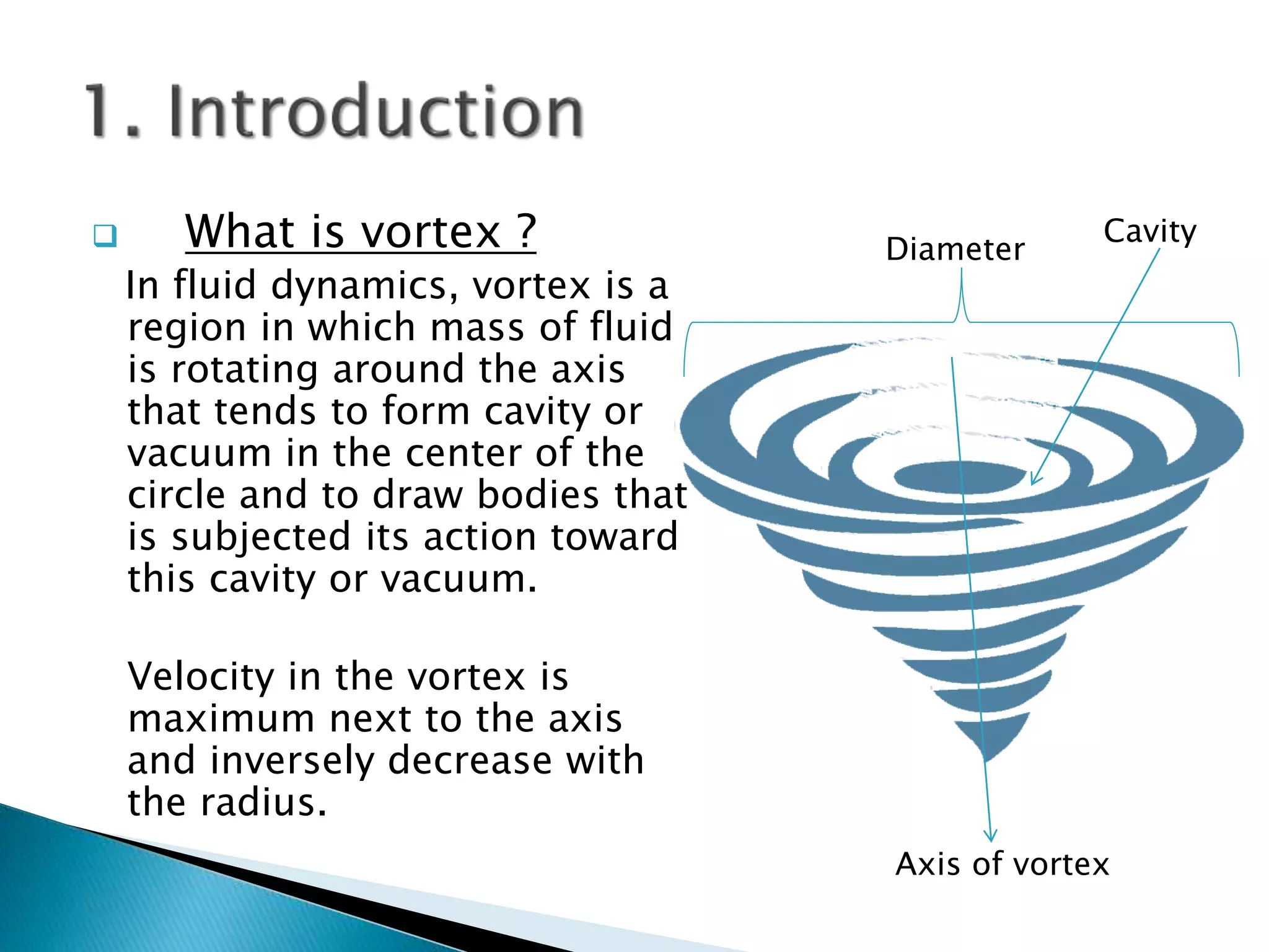
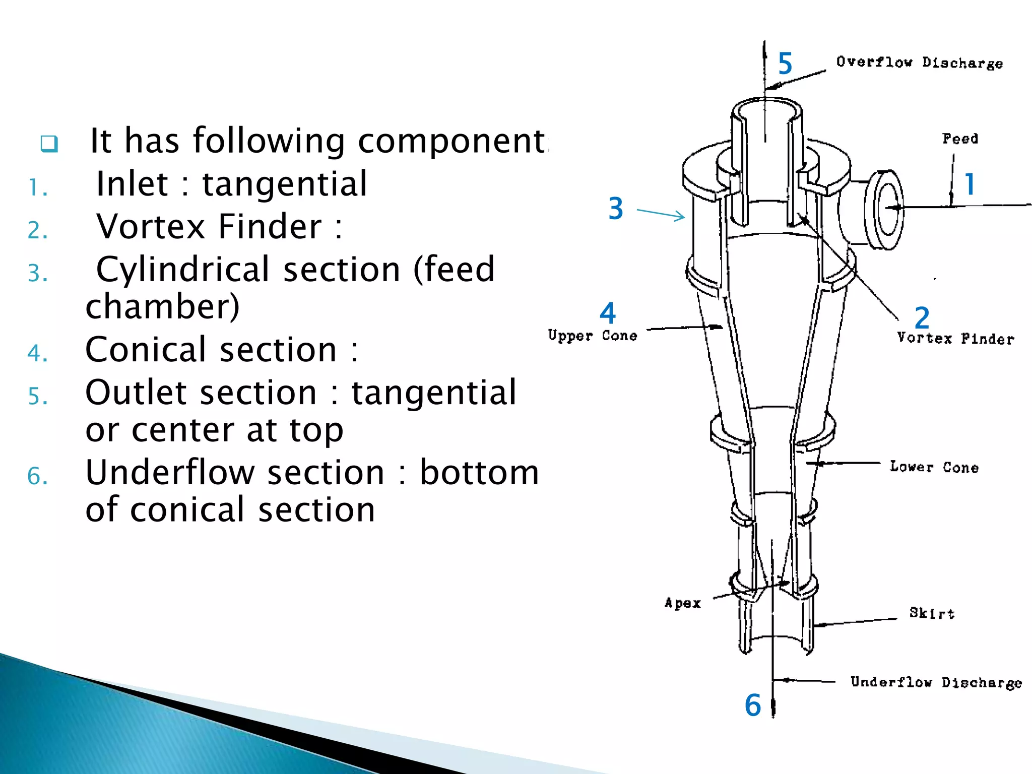
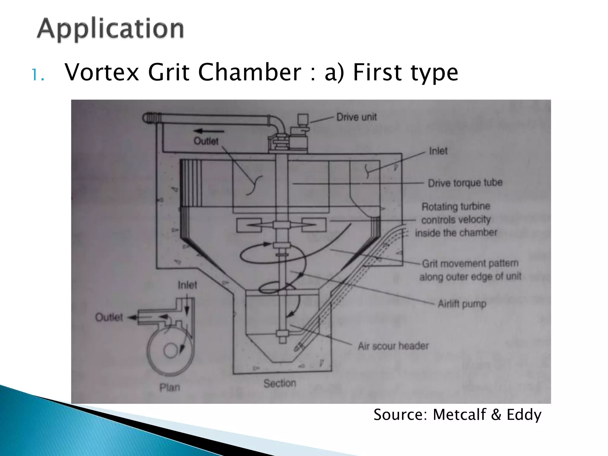
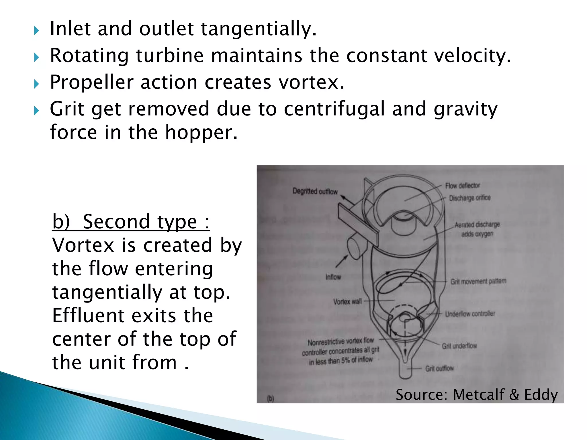
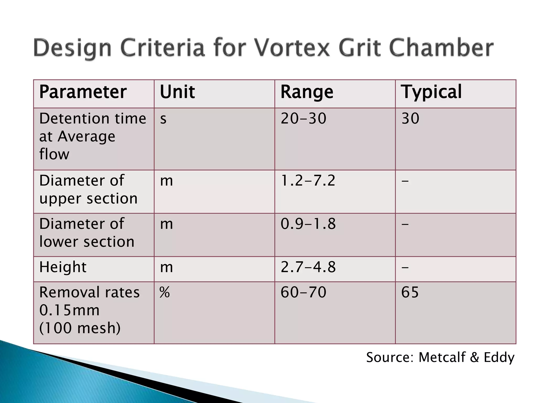
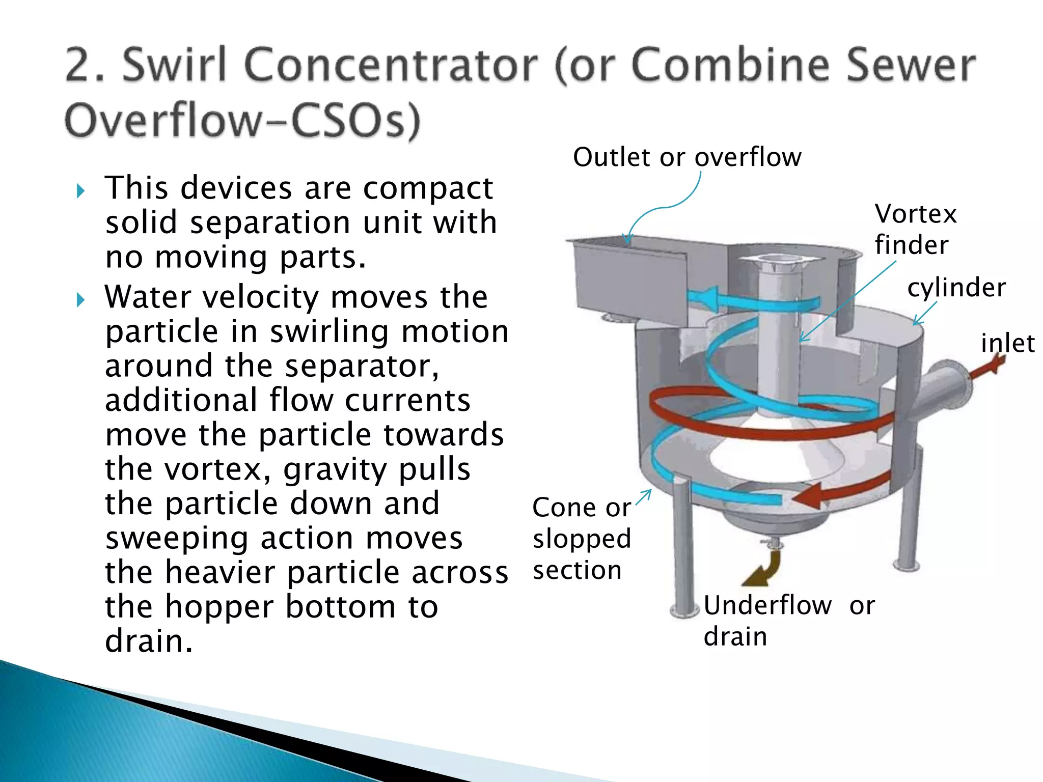
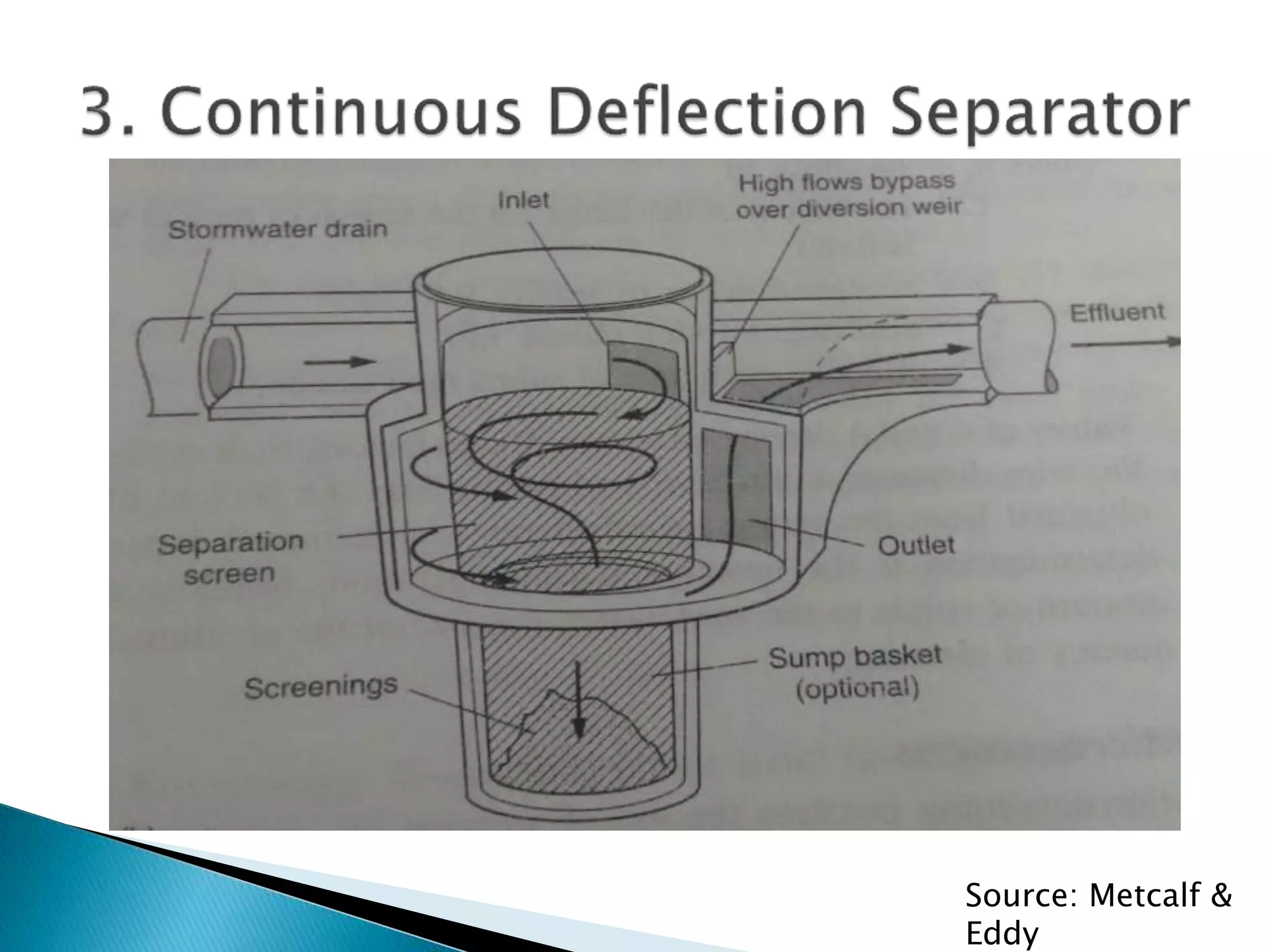
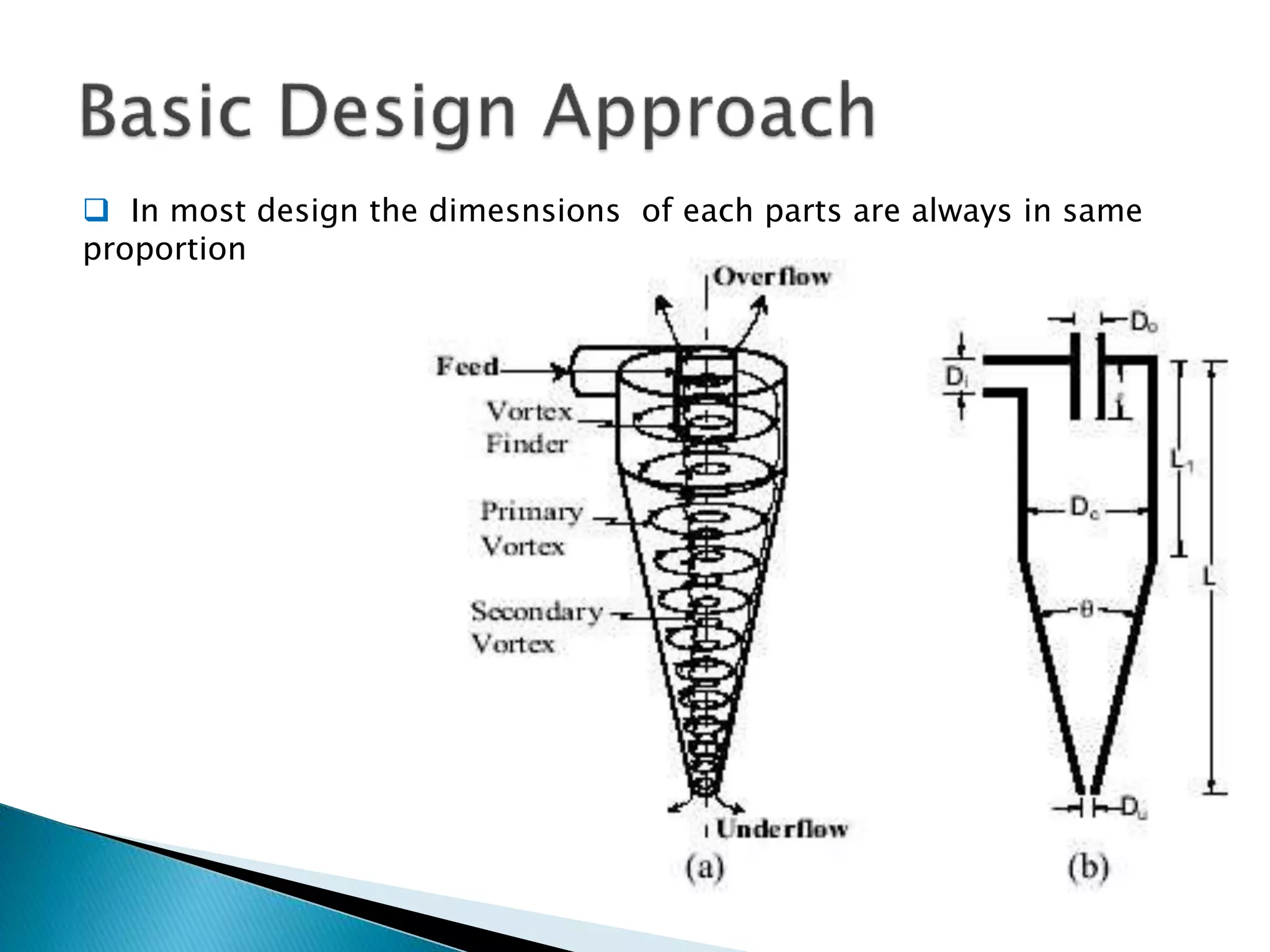
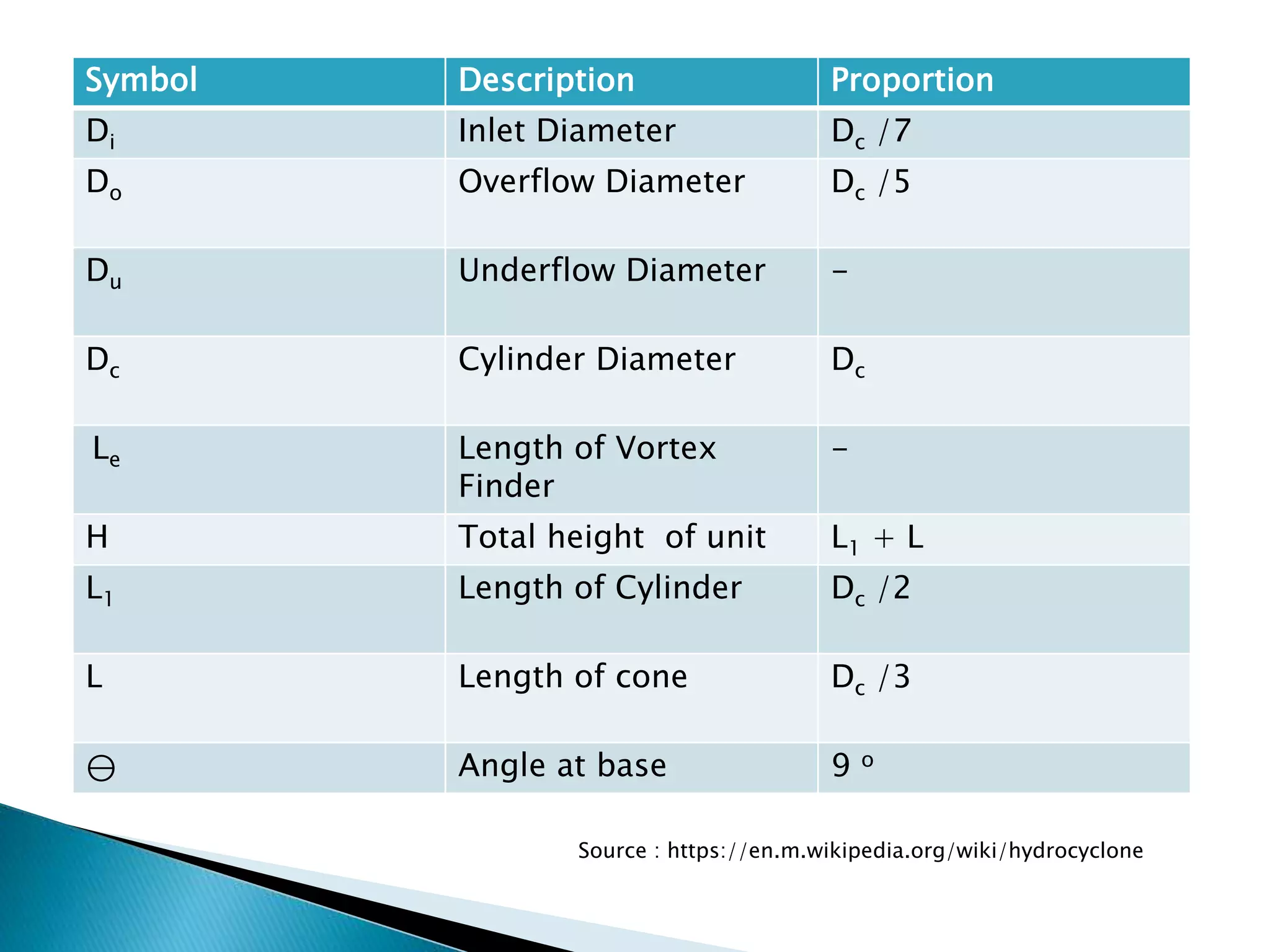
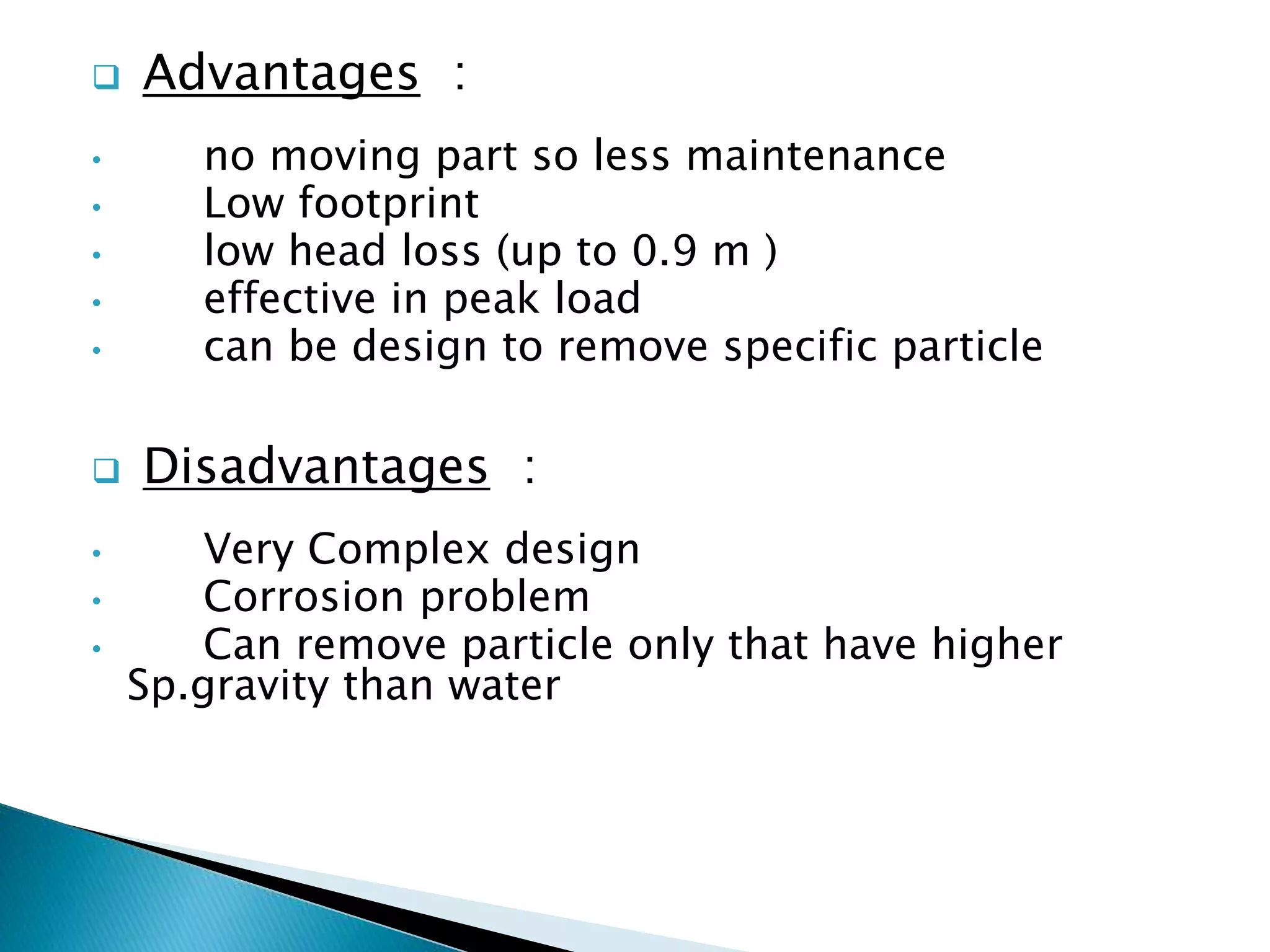
3. What is vortex ?
In fluid dynamics, vortex is a
region in which mass of fluid
is rotating around the axis
that tends to form cavity or
vacuum in the center of the
circle and to draw bodies that
is subjected its action toward
this cavity or vacuum.
Velocity in the vortex is
maximum next to the axis
and inversely decrease with
the radius.
Axis of vortex
Diameter
Cavity
4. Inertia is the resistance of the any physical
object to any change in its state of motion ;
this include changes to its speed , direction or
state. It is the tendency of object to keep
moving in the straight line with constant
velocity.
Centrifugal force is an inertial force that
directed away object from axis around which it
rotates.
Now Vortex separator is device that used to
separate the sediments from the fluid or two
different fluid that have different density.
5. It has following components:
1. Inlet : tangential
2. Vortex Finder :
3. Cylindrical section (feed
chamber)
4. Conical section :
5. Outlet section : tangential
or center at top
6. Underflow section : bottom
of conical section
1
2
3
4
5
6
6. The waste water enters the cylindrical section
tangentially.
The pressure of the wastewater at the inlet
influences the inlet velocity by means of an inlet
fixed cross section area.
The inlet velocities initiates a rotational pattern
that creates downward spiral in the feed chamber.
7. Centrifugal forces push the coarser material (or
higher specific gravity >= 2.65) outward towards
the cone wall. This increases the percent solids
near the wall by displacing the water towards the
center of the cone.
To counteract the crowding action as the cone
diameter decreases , a secondary interior spiral or
vortex is formed from the remaining w/w and fine
solids. This vortex causes the liquid and fine
solids to be carried up and out of the overflows.
The descending coarser solids will exit the cone
through the apex at relative high solids.
8. For Vortex : Velocity * Radius = constant
Centrifugal force = (tangential velocity )2 / radius
Particle size , Density and Drag
9. 1. Sediments having sp.gravity 2.65 or
greater (0.2 mm)
2. Metals
3. Organics (depends on sp.gravity)
4. Oil and grease
5. Floating matters
6. Nutrients (very low removal)
10. 1. Vortex Grit Chamber : a) First type
Source: Metcalf & Eddy
11. Inlet and outlet tangentially.
Rotating turbine maintains the constant velocity.
Propeller action creates vortex.
Grit get removed due to centrifugal and gravity
force in the hopper.
b) Second type :
Vortex is created by
the flow entering
tangentially at top.
Effluent exits the
center of the top of
the unit from .
Source: Metcalf & Eddy
12. Parameter Unit Range Typical
Detention time
at Average
flow
s 20-30 30
Diameter of
upper section
m 1.2-7.2 -
Diameter of
lower section
m 0.9-1.8 -
Height m 2.7-4.8 -
Removal rates
0.15mm
(100 mesh)
% 60-70 65
Source: Metcalf & Eddy
13. This devices are compact
solid separation unit with
no moving parts.
Water velocity moves the
particle in swirling motion
around the separator,
additional flow currents
move the particle towards
the vortex, gravity pulls
the particle down and
sweeping action moves
the heavier particle across
the hopper bottom to
drain.
inlet
Outlet or overflow
Vortex
finder
cylinder
Cone or
slopped
section
Underflow or
drain
15. How it is differ from conventional Vortex
separation :
It utilizes a filtration mechanism for solid
separation and does not rely on secondary flow
current induced by the vortex action.
Only one outlet.
Flow condition within the CDS separator have
different velocity profile. Surface velocity increases
with increasing the distance from the center of the
chamber(reverse of the conventional vortex
separator).
17. In most design the dimesnsions of each parts are always in same
proportion
18. Symbol Description Proportion
Di Inlet Diameter Dc /7
Do Overflow Diameter Dc /5
Du Underflow Diameter -
Dc Cylinder Diameter Dc
Le Length of Vortex
Finder
-
H Total height of unit L1 + L
L1 Length of Cylinder Dc /2
L Length of cone Dc /3
⊖ Angle at base 9 o
Source : https://en.m.wikipedia.org/wiki/hydrocyclone
19. Advantages :
• no moving part so less maintenance
• Low footprint
• low head loss (up to 0.9 m )
• effective in peak load
• can be design to remove specific particle
Disadvantages :
• Very Complex design
• Corrosion problem
• Can remove particle only that have higher
Sp.gravity than water