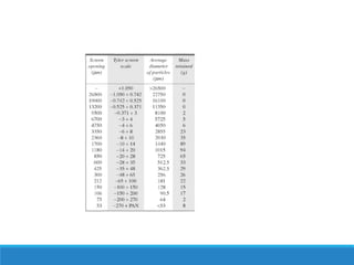
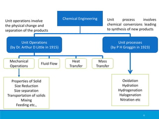
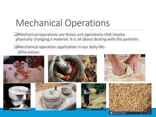
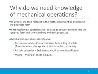
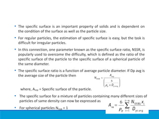
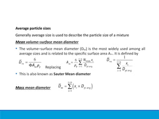
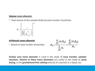
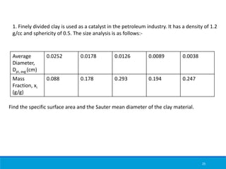
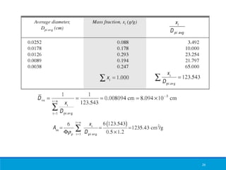
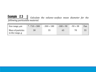
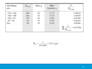
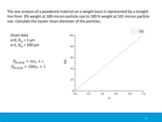
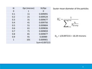
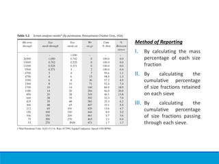
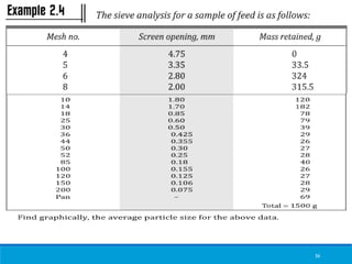
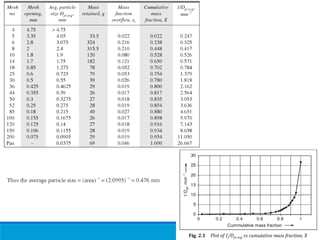
The document provides information about the evaluation scheme, course outcomes, history, and concepts of chemical engineering and mechanical operations for a course. It discusses particle characterization, average particle sizes including Sauter mean diameter, and provides an example calculation for determining Sauter mean diameter from size analysis data.
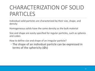
![Size of feed and product
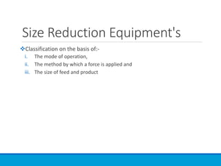
➢Coarse crushers (large feed size to (50-5) mm product size
➢Intermediate crushers [(50-5) mm to (5-1) mm product size]
➢Fine crushers/Grinders [(5-2) mm to ≈ 200 mesh]
➢Ultrafine grinders [6 mm to (1-50) µm]](https://image.slidesharecdn.com/module1-231010170610-ef0c820d/85/Module-1-pdf-61-320.jpg)
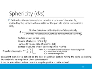
![Size of feed and product
➢Coarse crushers (large feed size to (50-5) mm product size
➢Intermediate crushers [(50-5) mm to (5-1) mm product size]
➢Fine crushers/Grinders [(5-2) mm to ≈ 200 mesh]
➢Ultrafine grinders [6 mm to (1-50) µm]](https://image.slidesharecdn.com/module1-231010170610-ef0c820d/85/Module-1-pdf-67-320.jpg)