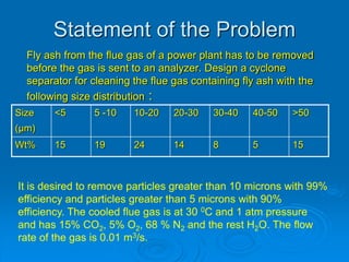
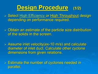
(1) A cyclone separator is needed to remove fly ash from flue gas from a power plant, with particles above 10 μm needing 99% removal and above 5 μm needing 90% removal.
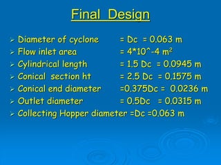
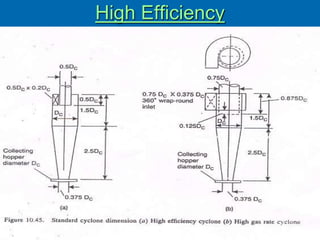
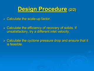
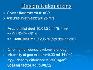
(2) A cyclone with a diameter of 0.063 m was designed, which could achieve the required efficiencies. Pressure drop and other design parameters were calculated.
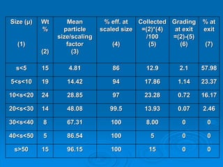
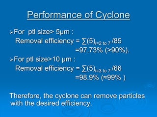
(3) The performance of the cyclone was analyzed through calculating particle size distribution at the inlet and outlet, showing the desired efficiencies were achieved.
![Formulae Used
Scaling Factor (Stairmand):
[(Dc2/Dc1)3 * (Q1/Q2) *(μ1/ μ2)* ( Δρ1/ Δρ2)]0.5
Where,
Dc1: diameter of standard cyclone= 8’’ (203 mm)
Dc2: diameter of proposed cyclone,mm
Q1 : standard flow rate
for high efficiency design= 223 m3/h
for high throughput design= 669 m3/h
Δρ1: solid-fluid density difference in standard conditions= 2000 kg/m3
Δρ2 : density difference, proposed design
μ1 : test viscosity fluid (air at 1 atm, 20º C)= 0.018 mN s/m2
μ2 : viscosity, proposed fluid](https://image.slidesharecdn.com/12-ed-i-cyclone-6s-r13-240319183810-73a67ecc/85/12-ed-i-cyclone-6s-r13-ppt-cyclone-separtor-11-320.jpg)
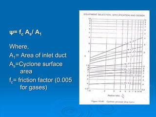
![ Pressure Drop Formula(Δp) =
(ρf /203)*{u1
2 [1+2φ2(2rt/re -1 )] + 2u2
2}
where,
Δp: pressure drop
ρf : gas density =0.8 kg/m3
u1 : inlet duct velocity
u2 : exit duct velocity
rt :radius of circle to which centre line of the inlet
is tangential
re :radius of exit pipe
Φ : Pressure drop correction factor](https://image.slidesharecdn.com/12-ed-i-cyclone-6s-r13-240319183810-73a67ecc/85/12-ed-i-cyclone-6s-r13-ppt-cyclone-separtor-15-320.jpg)