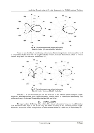
The document discusses the modeling of beamforming in circular antenna arrays with directional emitters, highlighting their ability to enhance the signal-to-interference ratio using adaptive beamforming techniques. It evaluates the spatial pattern formation of cylindrical antenna arrays through phased methods and the application of the Dolph-Chebyshev window to mitigate side lobe levels. The findings illustrate the improvements in beamforming efficiency and the reduction of sidelobes when directional factors are applied to antenna configurations.
![International Journal of Research in Engineering and Science (IJRES)
ISSN (Online): 2320-9364, ISSN (Print): 2320-9356
www.ijres.org Volume 5 Issue 3 ǁ Mar. 2017 ǁ PP.01-05
www.ijres.org 1 | Page
Modeling Beam forming in Circular Antenna Array with
Directional Emitters
Nechaev Yu.B.1
,Alkhafaji Sarmad K.D.1
,Peshkov I.W.2
1
(Information Systems Department, Voronezh State University, Russia)
2
(Radio Electronics And Computer Techniques Department, Bunin Yelets State University, Russia)
ABSTRACT: The article discusses the functioning of the radio direction-finding and beamforming methods in
the system of circular antenna arrays formed from the designed radiators, directional factor which is not equal to
1. Evaluation of forming of spatial pattern of cylindrical antenna array using phased method is fulfilled. Dolph-
Chebyshev window is used to reduce the side lobe level.
Keywords : Antenna, Cylindrical antenna; Direction-Finding; Digital Processing; Dolph-Chebyshev; Phased
array; Super resolution.
I. INTRODUCTION
Adaptive beamforming of antenna arrays (AR) can significantly increase the ratio of the transmitting
signal power to interference and noise power. One way it is beamforming based on an assessment of the angular
coordinates of radio sources. In such problems, the required number of primary modules processing the received
signals and analog-to-digital converters can reach high values [1]. The different configurations are used today,
but ones with the patch antennas which have the directive factor higher that one took great interest. One of the
most famous configuration is cylindrical antenna arrays.
II. PROBLEM FORMULATION
Let an antenna array consist of N antenna elements (AE). Let‟s assume, that M radio signals arriving on
the antenna array from distinct directions
1
0
,
M
mmm
. For an arbitrary geometry configuration antenna array a
complex output signal vector can be written as: [1]:
)()( ttt nsAx
, (1)
where T
tx
– N-dimensional vector describing output signals of each antenna element, )(ts
– M-dimensional
signal vector; tn
– N-dimensional noise vector of spatial channel and receiver; A – NM matrix of steering
vectors, mth column of the matrix describes phase distribution of mth signal source inside antenna array. Assume
that the antenna elements in the circular antenna array are identical and have a maximum radial direction from
the center of the array, 1,,1,0,
2
Nn
N
n
g
. In this case, the steering vector is defined as [2]:
T
N
N
rj
rj
e
N
N
geg
12
cos
cos 12
a , (2)
where
2
- wave number (λ – wave length), g - amplitude response of the antenna element (i.e., antenna
gain) in the direction of θ.
It should be noted that since the direction vector (2) represents the amplitude and phase responses of
the antennas in the composition of the lattice (1) from different incident waves, the gain g is the voltage gain (or
current) relative to the values that could be taken hypothetical isotropic antenna . Antennas are typically defined
in terms of their radiated (or received) power in a certain direction with respect to an isotropic antenna. If the
radiation pattern of the antenna power to designate as a linear gain G (θ) relative to an isotropic antenna, then
Gg .
To investigate the effect of the directivity of the accuracy of the direction-finding is necessary to have a
model of a hypothetical radiation pattern of the antenna. In this article the problems and limitations of the
antennas of the development process are not considered, the purpose of the work to investigate the effect of NAM
focus on the accuracy of radio direction finding. Model pattern of the antenna element in the far zone has](https://image.slidesharecdn.com/a530105-170713055647/85/Modeling-Beam-forming-in-Circular-Antenna-Array-with-Directional-Emitters-1-320.jpg)
![International Journal of Research in Engineering and Science (IJRES)
ISSN (Online): 2320-9364, ISSN (Print): 2320-9356
www.ijres.org Volume 5 Issue 3 ǁ Mar. 2017 ǁ PP.01-05
www.ijres.org 1 | Page
Modeling Beam forming in Circular Antenna Array with
Directional Emitters
Nechaev Yu.B.1
,Alkhafaji Sarmad K.D.1
,Peshkov I.W.2
1
(Information Systems Department, Voronezh State University, Russia)
2
(Radio Electronics And Computer Techniques Department, Bunin Yelets State University, Russia)
ABSTRACT: The article discusses the functioning of the radio direction-finding and beamforming methods in
the system of circular antenna arrays formed from the designed radiators, directional factor which is not equal to
1. Evaluation of forming of spatial pattern of cylindrical antenna array using phased method is fulfilled. Dolph-
Chebyshev window is used to reduce the side lobe level.
Keywords : Antenna, Cylindrical antenna; Direction-Finding; Digital Processing; Dolph-Chebyshev; Phased
array; Super resolution.
I. INTRODUCTION
Adaptive beamforming of antenna arrays (AR) can significantly increase the ratio of the transmitting
signal power to interference and noise power. One way it is beamforming based on an assessment of the angular
coordinates of radio sources. In such problems, the required number of primary modules processing the received
signals and analog-to-digital converters can reach high values [1]. The different configurations are used today,
but ones with the patch antennas which have the directive factor higher that one took great interest. One of the
most famous configuration is cylindrical antenna arrays.
II. PROBLEM FORMULATION
Let an antenna array consist of N antenna elements (AE). Let‟s assume, that M radio signals arriving on
the antenna array from distinct directions
1
0
,
M
mmm
. For an arbitrary geometry configuration antenna array a
complex output signal vector can be written as: [1]:
)()( ttt nsAx
, (1)
where T
tx
– N-dimensional vector describing output signals of each antenna element, )(ts
– M-dimensional
signal vector; tn
– N-dimensional noise vector of spatial channel and receiver; A – NM matrix of steering
vectors, mth column of the matrix describes phase distribution of mth signal source inside antenna array. Assume
that the antenna elements in the circular antenna array are identical and have a maximum radial direction from
the center of the array, 1,,1,0,
2
Nn
N
n
g
. In this case, the steering vector is defined as [2]:
T
N
N
rj
rj
e
N
N
geg
12
cos
cos 12
a , (2)
where
2
- wave number (λ – wave length), g - amplitude response of the antenna element (i.e., antenna
gain) in the direction of θ.
It should be noted that since the direction vector (2) represents the amplitude and phase responses of
the antennas in the composition of the lattice (1) from different incident waves, the gain g is the voltage gain (or
current) relative to the values that could be taken hypothetical isotropic antenna . Antennas are typically defined
in terms of their radiated (or received) power in a certain direction with respect to an isotropic antenna. If the
radiation pattern of the antenna power to designate as a linear gain G (θ) relative to an isotropic antenna, then
Gg .
To investigate the effect of the directivity of the accuracy of the direction-finding is necessary to have a
model of a hypothetical radiation pattern of the antenna. In this article the problems and limitations of the
antennas of the development process are not considered, the purpose of the work to investigate the effect of NAM
focus on the accuracy of radio direction finding. Model pattern of the antenna element in the far zone has](https://image.slidesharecdn.com/a530105-170713055647/75/Modeling-Beam-forming-in-Circular-Antenna-Array-with-Directional-Emitters-1-2048.jpg)
![Modeling Beamforming In Circular Antenna Array With Directional Emitters
www.ijres.org 2 | Page
m
cos1 response in the azimuthal plane, where m directivity control. Such NAM has CPV, which
increases with increasing m and has a maximum gain at θ = 0 °. This model is a close approximation of the
antennas which have the radiation on the back side, such as a microstrip antenna with a finite ground.
Furthermore, it is assumed that a symmetric Nam dimensional plane, then the normalized diagram for emitters
arranged in a ring, looks like [4, 5]:
1,,1,0,
2
cos1sin1
2
1
, 2
Nn
N
n
U
m
m
mn
(3)
It should be noted that the maximum of each element extends radially from the center of the ring are
uniformly distributed AR. Using a mathematical model DN (3) directional coefficient of each antenna element in
the composition calculated as the lattice [4, 5]:
2
0 0
22
sincos1sin1
2
dd
D
mm
m
(4)
For an isotropic antenna, m = 0 and D = 1 in the expression (4), and by increasing the D m orientation
also increases. For example, when m ≈ 2.7, D = 4 and when m ≈ 8,7, direction D = 10, etc.
From the expression (4) can be derived on a theoretical model DV power in the far field at plane φ = 90
° relative to an isotropic antenna, assuming that the antennas are perfectly matched and lossless [4, 5]:
1,,1,0,
2
cos1
22
Nn
N
nD
G
m
m
Fig. 1 shows the theoretical Nam hypothetical antenna for φ = 90 ° from the directional coefficients D =
2, 4, 10, 25, 50 (i.e., from 3 dBi to 17 dBi) and isotropic AE NAM for comparison.
Fig. 1. Curves for different spatial patterns D = 1, 2, 4, 10, 25, 50, φ = 90°.
The research of beamforming method via composed of circular antenna arrays depending on the
directivity of the antenna elements is fulfilled. Such antenna arrays composed of directed radiators, called
conformal. Range the directive factor wipe from 1 (omnidirectional transmitter) up to 30. If the number of
emitters equal to eight, and taking into account that the width of the substrate λ/2, take radius as 4/21 r ,
then gap (“Gap”) between the elements is empty (Fig. 2), also consider the configuration of radius λ.](https://image.slidesharecdn.com/a530105-170713055647/85/Modeling-Beam-forming-in-Circular-Antenna-Array-with-Directional-Emitters-2-320.jpg)
![Modeling Beamforming In Circular Antenna Array With Directional Emitters
www.ijres.org 3 | Page
Fig. 2. The circuit array of eight designed radiators, consisting of a substrate ( "Substrate") and the radiator (
"Patch").
In telecommunication systems, when the output signal of time k is obtained as data by linear
combination with N antenna elements [3]:
)()( kky H
xw
,
where w
– vector of weights. While changing w
, the beam pattern can be positioned in any direction of the
radiation pattern and adaptively control its shape to the total power of interference and additive noise was
minimal with minimal distortion of the useful signal, i.e. .:
}{min ni
H
w
E xw
, при 11 aw
H
where nix
– signal from the antenna elements of the array, containing only interference and noise. In this beam
shaper the weight vector is selected to be equal to the steering vector of the desired signal, i.e. [3]:
)( 1aw
.
Here, the radiation pattern comprises a maximum in the direction θ1. This usually has high side lobes,
then weighting vector required (here we use the Chebyshev window to reduce the sidelobe level to -30 dB). The
presence of sidelobes means that the array is radiating energy in untended directions. Additionally, due to
reciprocity, the array is receiving energy from unintended directions. In a multipath environment, the sidelobes
can receive the same signal from multiple angles. This is the basis for fading experienced in communications.
The sidelobes can be suppressed by weighting, shading, or windowing the array elements [3]. Then the vector of
weights:
taw
0 ,
where t
– windowing vector.
Using Dolph-Chebyshev method of windowing for eight element antenna array allows computing the
following coefficients: 1.0000, 0.6242, 0.2254, 0.0364, 0.0364, 0.2254, 0.6242, 1.0000. In this case, the
radiating elements in the opposite direction from the signal source just „off‟ (Fig. 3).
Fig. 3. Window of Dolph-Chebyshev](https://image.slidesharecdn.com/a530105-170713055647/85/Modeling-Beam-forming-in-Circular-Antenna-Array-with-Directional-Emitters-3-320.jpg)
![Modeling Beamforming In Circular Antenna Array With Directional Emitters
www.ijres.org 5 | Page
REFERENCES
[1]. Krim H. Two decades of array signal processing research / H. Krim, M. Viberg // IEEE Signal
Processing Magazine. – 1996. – Vol. 7. – P. 67-94.
[2]. Jackson B. R. Direction of Arrival Estimation Using Directive Antennas in Uniform Circular Arrays /
Jackson Brad R., Rajan Sreeraman, Liao Bruce J., Wang Sichun // EEE Transactions on Antennas and
Propagation. - vol. 63, issue 2. - pp. 736-747.
[3]. Gross F.B Smart antennas for wireless communications : with Matlab / F.B. Gross. – New York :
McGraw-Hill Professional, 2005. – 288 p.
[4]. Jackson B. R. Direction of Arrival Estimation Using Directive Antennas in Uniform Circular Arrays /
Jackson Brad R., Rajan Sreeraman, Liao Bruce J., Wang Sichun // EEE Transactions on Antennas and
Propagation. - vol. 63, issue 2. - pp. 736-747.
[5]. J. D. Kraus, Antennas. McGraw-Hill, 1988.](https://image.slidesharecdn.com/a530105-170713055647/85/Modeling-Beam-forming-in-Circular-Antenna-Array-with-Directional-Emitters-5-320.jpg)


![[Deck] What's New in Spark-Iceberg Integration via DSV2.pptx](https://cdn.slidesharecdn.com/ss_thumbnails/deckwhatsnewinspark-icebergintegrationviadsv2-260210005337-25955b12-thumbnail.jpg?width=640&height=640&fit=bounds)


