
Recommended
Recommended
More Related Content
What's hot
What's hot (20)
Similar to False Peaks Occuring at Direction-Finding Via Cylindrical Antenna Array with The Directional Emitters
Similar to False Peaks Occuring at Direction-Finding Via Cylindrical Antenna Array with The Directional Emitters (20)
More from IJRESJOURNAL
More from IJRESJOURNAL (20)
Recently uploaded
Recently uploaded (20)
False Peaks Occuring at Direction-Finding Via Cylindrical Antenna Array with The Directional Emitters
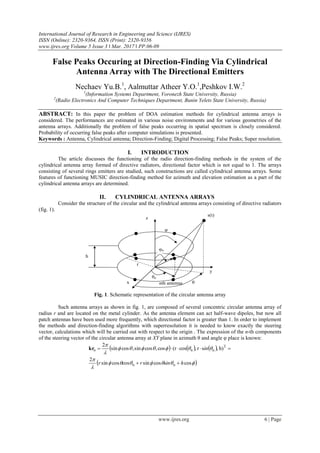
- 1. International Journal of Research in Engineering and Science (IJRES) ISSN (Online): 2320-9364, ISSN (Print): 2320-9356 www.ijres.org Volume 5 Issue 3 ǁ Mar. 2017 ǁ PP.06-09 www.ijres.org 6 | Page False Peaks Occuring at Direction-Finding Via Cylindrical Antenna Array with The Directional Emitters Nechaev Yu.B.1 , Aalmuttar Atheer Y.O.1 ,Peshkov I.W.2 1 (Information Systems Department, Voronezh State University, Russia) 2 (Radio Electronics And Computer Techniques Department, Bunin Yelets State University, Russia) ABSTRACT: In this paper the problem of DOA estimation methods for cylindrical antenna arrays is considered. The performances are estimated in various noise environments and for various geometries of the antenna arrays. Additionally the problem of false peaks occurring in spatial spectrum is closely considered. Probability of occurring false peaks after computer simulations is presented. Keywords : Antenna, Cylindrical antenna; Direction-Finding; Digital Processing; False Peaks; Super resolution. I. INTRODUCTION The article discusses the functioning of the radio direction-finding methods in the system of the cylindrical antenna array formed of directive radiators, directional factor which is not equal to 1. The arrays consisting of several rings emitters are studied, such constructions are called cylindrical antenna arrays. Some features of functioning MUSIC direction-finding method for azimuth and elevation estimation as a part of the cylindrical antenna arrays are determined. II. CYLINDRICAL ANTENNA ARRAYS Consider the structure of the circular and the cylindrical antenna arrays consisting of directive radiators (fig. 1). s(t) φ θ r z y x nth antenna θn h φn Fig. 1. Schematic representation of the circular antenna array Such antenna arrays as shown in fig. 1, are composed of several concentric circular antenna array of radius r and are located on the metal cylinder. As the antenna element can act half-wave dipoles, but now all patch antennas have been used more frequently, which directional factor is greater than 1. In order to implement the methods and direction-finding algorithms with superresolution it is needed to know exactly the steering vector, calculations which will be carried out with respect to the origin . The expression of the n-th components of the steering vector of the circular antenna array at XY plane in azimuth θ and angle φ place is known: cosscossincoscossin 2 h),sr,cos(rcos,cossin,cossin 2 nn T nn hinrr inn kr
- 2. False Peaks Occuring At Direction-Finding Via Cylindrical Antenna Array with www.ijres.org 7 | Page III. STUDY Fig. 2. Schematic representation of the cylindrical antenna array. The researching of the direction finding method with superresolution MUSIC (2) is fulfilled as part of the cylindrical antenna array (fig. 2), depending on the directivity of the antenna elements. The range of the directive factor wipes 1 (omnidirectional) to 20. Consider a situation with multiple sources of radio emissions, the coordinates of which are θ1=0°, φ1=45° and θ2=25°, φ2=45°. Fig. 3. Spatial spectrum of the method MUSIC for the cylindrical antenna array, composed of a) one circular array, 4/21 r , directive factor=2; b) one circular array, r , directive factor =2; c) two circular arrays, 4/21 r , directive factor =2; d) two circular arrays, r , directive factor=2. Fig. 3 a, b) shows the spatial characteristics of the MUSIC method for the cylindrical antenna array consisting of the eight-elements circular antenna array, and Fig. 3, d) - two of the four-elements circular antenna array. From graphs it is seen that the multilayered configurations give more distinct peaks, which in turn is reflected in higher resolution and accuracy. It should be noted that due to the large area arrays with a radius of r that cause less the appearances of errors in comparison direction finding with the arrays of radius Z Y X h=λ Elevation, (°)
- 3. False Peaks Occuring At Direction-Finding Via Cylindrical Antenna Array with www.ijres.org 8 | Page 4/21 r . Consider other features with superresolution direction finding in azimuth and elevation by using cylindrical antennas with the directive factor higher than 1. Fig. 4. Spatial spectrum of the method MUSIC for the cylindrical antenna array, composed of a) one circular array, 4/21 r , directive factor =6; b) one circular array, r , directive factor =4. Fig. 4 shows typical spectra of two dimensional graphic views: a propagated peaks (figure 4 a, b.), and with an additional maximum (figure 4a.) Caused by a high coefficient of directional directivity diagrams antenna element. These features prevent the accurate determination of the signal source coordinates. Let us consider cylindrical antenna array of eight elements with radius 4/21 r and r . Additionally we may regard the cylindrical antenna array with two CARs out of four and four antenna elements, having the same radii with radius 4/21 r and r . We have added noise of SNR -10 dB to measure statistically the probability of occurring false peaks. Two signals impinge at the arrays with coordinates θ1=0°, φ1=45°, θ2=25°, φ2=45°. In this experiment we try to measure how often the false peaks occur using different conditions and environments. While calculating the function of method MUSIC [4], we increment the counter of the occurrence of false peaks in case it is possible to identify more peaks than the number of signals which is supposed to be known. The number of iterations is 500. Fig. 5. The number of false peaks occurring depending on directivity factor for various cylindrical antenna array configurations Elevation, (°) falsepeaksoccurs
- 4. False Peaks Occuring At Direction-Finding Via Cylindrical Antenna Array with www.ijres.org 9 | Page As can be seen from the graphs in Fig. 5, the number of false peaks increases with increasing the directivity of all the considered configurations. This is due to the fact that is formed Highly-directional pattern of antenna array, whereby signals fall only on the side lobes, which level is very low in comparison with the maximum. This behavior is particularly distinguished by cylindrical arrays formed from only one ring of directive emitters. If you use two rings, located one above the other, as shown in Fig. 2, then wider beam patterns is formed at a comparable rate of directivity, and then signals do not fall on the sidelobes, but fall on a maximum and suppression of the signals do not happen. Worth noting that the increase in the radius of the antenna array can reduce the number of occurrences of false peaks, but only slightly. Therefore, to reduce the occurrence of these peaks the antenna array must be used, which consists of a few circular arrays of directive emitters, arranged, where possible, on a larger radius. If we consider the false peaks distributions generated by the antenna arrays, then it is obvious that their occurrence is basically treatable character and they lay in the vicinity of the true coordinates of the signals sources. These distributions can be easily processed by the clustering algorithms, for example k-means, after that inside each cluster a peak can be chosen with the highest value of the function MUSIC. IV. CONCLUSIONS The paper studied the effect of the particular directional factor of an antenna element composed of a cylindrical antenna array to assess angular coordinates MUSIC method procedure. These configurations allow estimating the directions of arrival of electromagnetic waves on azimuth and elevation planes. The phenomenon gives rise to several false peaks on the spatial spectrum along with the peaks pointing to actual signal coordinates. The probability of the occurring false peaks is measured by means of simulation of various noise environments. It is established that the more aperture, the less probability is. Additionally the more rings is used the less probability is. Comparative modeling of cylindrical antenna arrays for radio direction-finding tasks is obtained via spectral characteristics MUSIC method. It was found that to obtain accurate estimates of the angular coordinates of radiation sources should be used the cylindrical antenna array consisting of several the circular antenna array at different levels relative to each other. REFERENCES [1] Krim H. Two decades of array signal processing research / H. Krim, M. Viberg // IEEE Signal Processing Magazine. – 1996. – Vol. 7. – P. 67-94. [2] Trees Van H.L. Detection, Estimation, and Modulation Theory, Optimum Array Processing / H.L. Trees Van. - John Wiley & Sons, 2002. – 1470 p. [3] J. Liu, l. Li, and W. Huazhi, “Investigation of different types of array structures for smart antennas,” in Int. Conf. on Microwave and Millimeter Wave Technology (ICMMT), 2008, pp. 1160–1163. [4] R.O. Schmidt, Multiple emitter location and signal parameter estimation, IEEE Transactions on Antennas and Propagation 34 (3) (1986) 276–280. [5] Balanis C.A. Antenna theory : analysis and design / C.A. Balanis. – New York : John Wiley and Sons, 2005. – 1165 p.