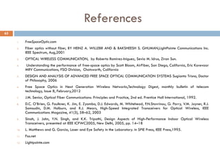
Download as PDF, PPTX

![Fiber is …
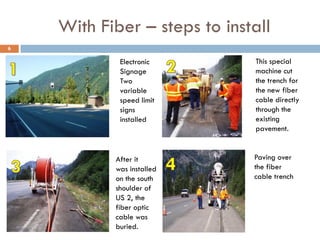
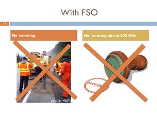
But Sunk Cost as they cost US $100000-
$200000/km in metropolitan areas, with
85 percent of the total figure tied to
trenching and installation.[1]
7](https://image.slidesharecdn.com/finalppt-140322125328-phpapp01/85/Free-Space-Optics-7-320.jpg)

![Advantages
Higher bandwidth
Low Cost-These free-space systems require less
than a fifth the capital outlay of comparable
ground-based fiber-optic technologies[2]
14](https://image.slidesharecdn.com/finalppt-140322125328-phpapp01/85/Free-Space-Optics-14-320.jpg)

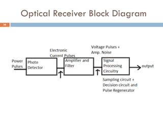

The document describes the design of a free space optical link. It begins with an overview of what free space optical communication is and its advantages over other wired technologies. It then discusses the basic components of an FSO link including the transmitter, receiver, and transceiver implementation. The transmitter section focuses on the laser diode source and driver circuitry. The receiver section covers the photodetector, preamplifier, and decision circuitry. Lastly, it discusses modeling the FSO channel and the factors that can impact signal propagation through the atmosphere.