Downloaded 1,324 times
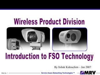
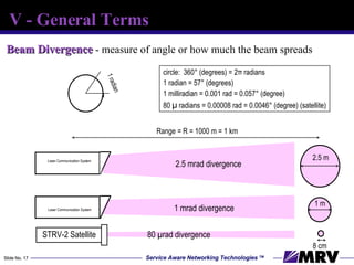
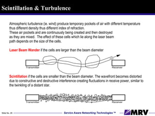
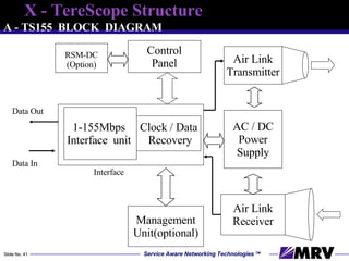
![Geometric loss Beam Area Receiver Lens Area d B = divergence angle, d B = R GM (Geometric Loss) = 10 log (Rx lens Area/Beam Area) = 10 log [d R /( R )] 2 d R R (air transmission distance) Tx](https://image.slidesharecdn.com/introductiontofsotechnology-1216024918992120-8/85/Introduction-To-Fso-Technology-19-320.jpg)
![THANK YOU ww.mrv.com [email_address]](https://image.slidesharecdn.com/introductiontofsotechnology-1216024918992120-8/85/Introduction-To-Fso-Technology-44-320.jpg)

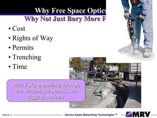
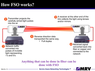
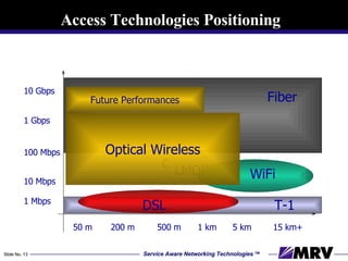
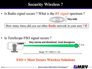
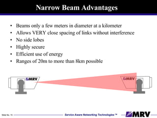
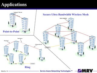
The document introduces Free Space Optics (FSO) technology, which uses laser light for high-speed communication without the need for permits or extensive installations, capable of achieving speeds up to 1 Gbps over distances of 5 km. FSO addresses the 'last mile' connectivity challenge, offering a cost-effective and secure alternative to traditional fiber and radio technologies. The document also highlights the advantages, applications, and environmental considerations of FSO, emphasizing its potential in various global installations.


![Getting Started with Apache Spark: Big Data Made Simple [Free Meetup]](https://cdn.slidesharecdn.com/ss_thumbnails/apachesparkgettingstarted-260203175547-8361bcc3-thumbnail.jpg?width=640&height=640&fit=bounds)


