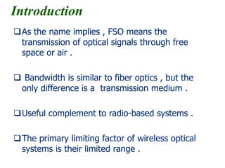
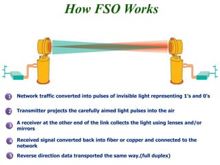
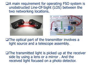
Free-Space Optical
(FSO)
Communication Systems
Aydin Amini
2015 School of
Engineering-Emerging
Technologies,
University of Tabriz
Introduction
As the name implies , FSO means the
transmission of optical signals through free
space or air .
 Bandwidth is similar to fiber optics , but the
only difference is a transmission medium .
Useful complement to radio-based systems .
The primary limiting factor of wireless optical
systems is their limited range .
Applications:
- Wireless control devices
- Wireless communication
How FSO Works
1
3
4
Network traffic converted into pulses of invisible light representing 1’s and 0’s
Transmitter projects the carefully aimed light pulses into the air2
A receiver at the other end of the link collects the light using lenses and/or
mirrors
Received signal converted back into fiber or copper and connected to the
network
5 Reverse direction data transported the same way.(full duplex)
A main requirement for operating FSO system is
unobstructed Line-Of-Sight (LOS) between the
two networking locations.
The optical part of the transmitter involves a
light source and a telescope assembly.
The transmitted light is picked up at the receiver
side by using a lens or a mirror . And the
received light focused on a photo detector.
System uses intensity modulation with direct
detection (IM/DD) to achieve optical modulation
and demodulation.
Link type:
- Point to point system
- Diffuse system
Point-to-point systems:
- Transmitter and receiver pointed at each other.
- The LOS path from the transmitter to the
receiver must be clear of obstructions .
- Point to point systems are also called directed
LOS systems.
Diffuse systems:
- The link is always maintained between any
transmitter and any receiver in the same vicinity
by reflecting or bouncing the transmitted
information .
- The transmitter and receiver are non-directed.
- The diffuse systems are also called non-directed
non-LOS systems.
FSO major subsystems
Transmitter:
 LED (Light-emitting diode)
 LD (laser diode):
Laser diode selection criteria for FSO :
1) Price and availability of commercial components
2) Transmission power
3) Life time
4) Modulation capabilities
5) Eye safety
6) Physical dimensions
7) Compatibility with other transmission media Such
as fiber.
safety
Eye safety:
- The cornea is transparent near the IR .
- The near IR is outside the visible range of light , and
so the eye does no protect itself by closing the
eyelid.
Skin safety:
- Short-term effects
- Long-term effects
Receiver:
 Silicon p-i-n photodiodes:
- Creates an electron-hole Pair when a photon
Strikes The photodiode’s surface
 Avalanche photodiode (APD):
- Have a internal current gain effect due to
avalanche effect (impact ionization)
Detectors selection criteria for FSO :
1) Responsivity :
- measures the gain of a detector system.
2) Rise time:
3) Quantum efficiency:
- incident photon to converted electron ratio
The FSO System Design
Internal parameters:
1) Optical power
2) Wavelength
3) Transmission bandwidth
4) Optical loss
5) Transmitter angle of divergence (AOD)
6) Receiver sensitivity
7) Receiver lens diameter
8) Receiver Field of view (FOV)
Wavelength interval selection for FSO systems:
- First wavelength interval is between 780nm
and 850nm .
- The latter wavelength interval is between
1529nm and 1600nm .
External parameters:
1) Alignment
2) Atmospheric attenuation
3) Scintillation
4) Physical obstructions
5) Window loss
Atmospheric attenuation:
Caused by low clouds , rain , snow , dust , and
mainly by fog.
 Fog: modify light characteristics or completely
hinder the passage of light through them
through a combination of absorption,scattering
and reflection.
Solution:
- Increasing the transmit power.
- Reducing the distance between the transmitter and
the receiver.
 Physical obstructions:
- Birds
- Building sway
 Window attenuation:
 Scintillation:
- Changing of light intensities
- Beam spreading and wandering
 Mis-Alignment :
Caused by spreading the diameter of
Transmitted beam, this narrow transmitted
beam will arrive at the narrow field-of-view.
Noise in FSO:
- The detector is illuminated by sources of light
energy other than the main source.
- Noise is also called background light.
Noise can be broken into four components:
1) Photon noise or shot noise
2) Gain noise
3) Thermal noise
4) Periodic noise
Shot noise effect
Periodic noise effect
Optical filters used in FSO
Used to reject out of band ambient radiation and
reduce the intensity reaching the detector.
 Low-pass filter in combination with a silicon detector
provides a natural narrowing of the bandwidth.
 Absorption filters can be used to reject solar and
illumination
 Band-pass interference filters
Advantages of FSO
1) High rates
2) No frequency license required
3) Fast and easy installation
4) Distance up to kms (20m – 8km)
5) Compatible with other access technology
6) Cost effective , movable asset
7) Internal and external mounting

Free Space Optical Communication

  • 1.
    Free-Space Optical (FSO) Communication Systems AydinAmini 2015 School of Engineering-Emerging Technologies, University of Tabriz
  • 2.
    Introduction As the nameimplies , FSO means the transmission of optical signals through free space or air .  Bandwidth is similar to fiber optics , but the only difference is a transmission medium . Useful complement to radio-based systems . The primary limiting factor of wireless optical systems is their limited range .
  • 3.
    Applications: - Wireless controldevices - Wireless communication
  • 4.
    How FSO Works 1 3 4 Networktraffic converted into pulses of invisible light representing 1’s and 0’s Transmitter projects the carefully aimed light pulses into the air2 A receiver at the other end of the link collects the light using lenses and/or mirrors Received signal converted back into fiber or copper and connected to the network 5 Reverse direction data transported the same way.(full duplex)
  • 5.
    A main requirementfor operating FSO system is unobstructed Line-Of-Sight (LOS) between the two networking locations. The optical part of the transmitter involves a light source and a telescope assembly. The transmitted light is picked up at the receiver side by using a lens or a mirror . And the received light focused on a photo detector.
  • 6.
    System uses intensitymodulation with direct detection (IM/DD) to achieve optical modulation and demodulation. Link type: - Point to point system - Diffuse system
  • 7.
    Point-to-point systems: - Transmitterand receiver pointed at each other. - The LOS path from the transmitter to the receiver must be clear of obstructions . - Point to point systems are also called directed LOS systems.
  • 8.
    Diffuse systems: - Thelink is always maintained between any transmitter and any receiver in the same vicinity by reflecting or bouncing the transmitted information . - The transmitter and receiver are non-directed. - The diffuse systems are also called non-directed non-LOS systems.
  • 9.
    FSO major subsystems Transmitter: LED (Light-emitting diode)  LD (laser diode):
  • 10.
    Laser diode selectioncriteria for FSO : 1) Price and availability of commercial components 2) Transmission power 3) Life time 4) Modulation capabilities 5) Eye safety 6) Physical dimensions 7) Compatibility with other transmission media Such as fiber.
  • 11.
    safety Eye safety: - Thecornea is transparent near the IR . - The near IR is outside the visible range of light , and so the eye does no protect itself by closing the eyelid. Skin safety: - Short-term effects - Long-term effects
  • 12.
    Receiver:  Silicon p-i-nphotodiodes: - Creates an electron-hole Pair when a photon Strikes The photodiode’s surface
  • 13.
     Avalanche photodiode(APD): - Have a internal current gain effect due to avalanche effect (impact ionization)
  • 14.
    Detectors selection criteriafor FSO : 1) Responsivity : - measures the gain of a detector system. 2) Rise time: 3) Quantum efficiency: - incident photon to converted electron ratio
  • 15.
    The FSO SystemDesign Internal parameters: 1) Optical power 2) Wavelength 3) Transmission bandwidth 4) Optical loss 5) Transmitter angle of divergence (AOD) 6) Receiver sensitivity 7) Receiver lens diameter 8) Receiver Field of view (FOV)
  • 16.
  • 17.
    - First wavelengthinterval is between 780nm and 850nm . - The latter wavelength interval is between 1529nm and 1600nm .
  • 18.
    External parameters: 1) Alignment 2)Atmospheric attenuation 3) Scintillation 4) Physical obstructions 5) Window loss
  • 19.
    Atmospheric attenuation: Caused bylow clouds , rain , snow , dust , and mainly by fog.  Fog: modify light characteristics or completely hinder the passage of light through them through a combination of absorption,scattering and reflection. Solution: - Increasing the transmit power. - Reducing the distance between the transmitter and the receiver.
  • 20.
     Physical obstructions: -Birds - Building sway  Window attenuation:
  • 21.
     Scintillation: - Changingof light intensities - Beam spreading and wandering
  • 22.
     Mis-Alignment : Causedby spreading the diameter of Transmitted beam, this narrow transmitted beam will arrive at the narrow field-of-view.
  • 23.
    Noise in FSO: -The detector is illuminated by sources of light energy other than the main source. - Noise is also called background light. Noise can be broken into four components: 1) Photon noise or shot noise 2) Gain noise 3) Thermal noise 4) Periodic noise
  • 24.
  • 25.
  • 26.
    Optical filters usedin FSO Used to reject out of band ambient radiation and reduce the intensity reaching the detector.  Low-pass filter in combination with a silicon detector provides a natural narrowing of the bandwidth.  Absorption filters can be used to reject solar and illumination  Band-pass interference filters
  • 27.
    Advantages of FSO 1)High rates 2) No frequency license required 3) Fast and easy installation 4) Distance up to kms (20m – 8km) 5) Compatible with other access technology 6) Cost effective , movable asset 7) Internal and external mounting