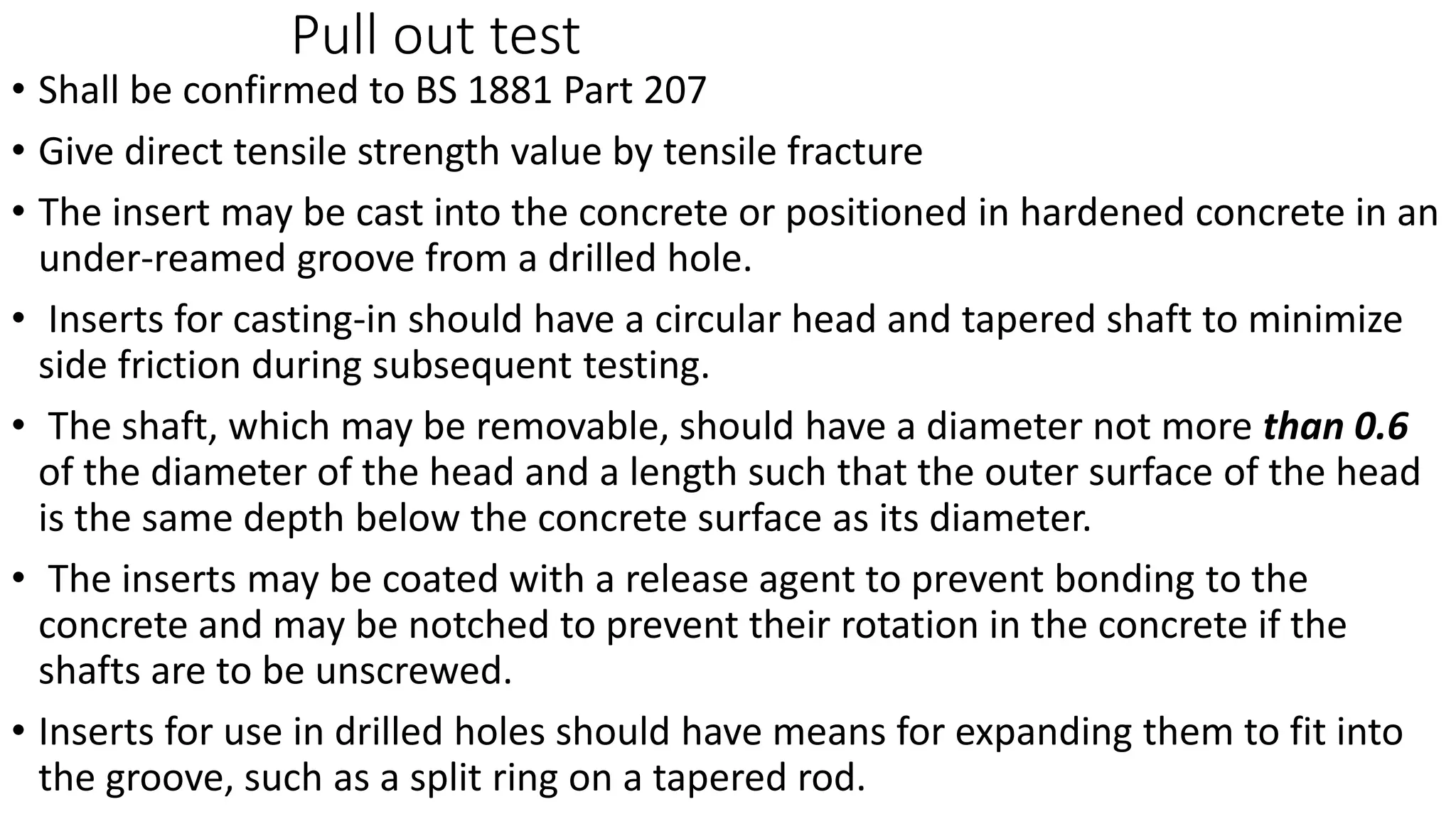
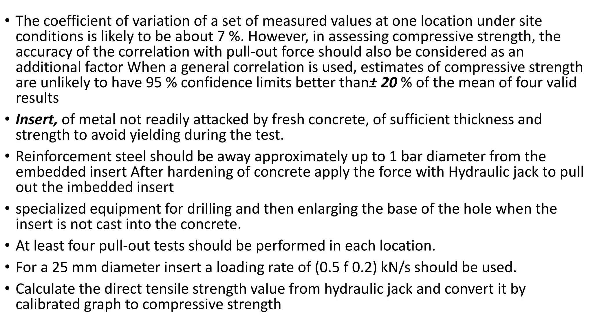
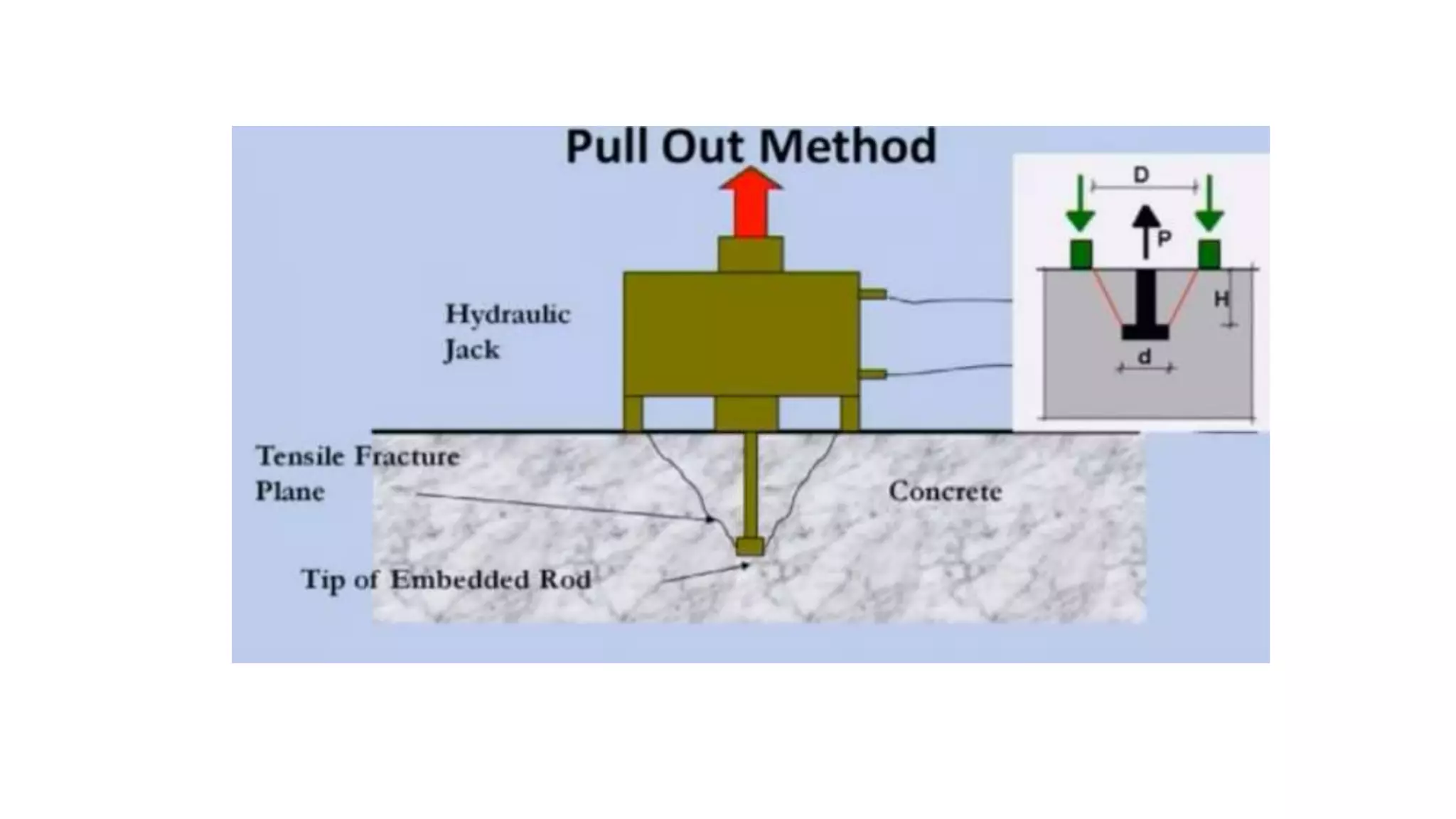
Pull out test
• Shall be confirmed to BS 1881 Part 207
• Give direct tensile strength value by tensile fracture
• The insert may be cast into the concrete or positioned in hardened concrete in an
under-reamed groove from a drilled hole.
• Inserts for casting-in should have a circular head and tapered shaft to minimize
side friction during subsequent testing.
• The shaft, which may be removable, should have a diameter not more than 0.6
of the diameter of the head and a length such that the outer surface of the head
is the same depth below the concrete surface as its diameter.
• The inserts may be coated with a release agent to prevent bonding to the
concrete and may be notched to prevent their rotation in the concrete if the
shafts are to be unscrewed.
• Inserts for use in drilled holes should have means for expanding them to fit into
the groove, such as a split ring on a tapered rod.
• The coefficient of variation of a set of measured values at one location under site
conditions is likely to be about 7 %. However, in assessing compressive strength, the
accuracy of the correlation with pull-out force should also be considered as an
additional factor When a general correlation is used, estimates of compressive strength
are unlikely to have 95 % confidence limits better than± 20 % of the mean of four valid
results
• Insert, of metal not readily attacked by fresh concrete, of sufficient thickness and
strength to avoid yielding during the test.
• Reinforcement steel should be away approximately up to 1 bar diameter from the
embedded insert After hardening of concrete apply the force with Hydraulic jack to pull
out the imbedded insert
• specialized equipment for drilling and then enlarging the base of the hole when the
insert is not cast into the concrete.
• At least four pull-out tests should be performed in each location.
• For a 25 mm diameter insert a loading rate of (0.5 f 0.2) kN/s should be used.
• Calculate the direct tensile strength value from hydraulic jack and convert it by
calibrated graph to compressive strength
Pull out test for concrete

Pull out test for concrete

  • 1.
    Pull out test •Shall be confirmed to BS 1881 Part 207 • Give direct tensile strength value by tensile fracture • The insert may be cast into the concrete or positioned in hardened concrete in an under-reamed groove from a drilled hole. • Inserts for casting-in should have a circular head and tapered shaft to minimize side friction during subsequent testing. • The shaft, which may be removable, should have a diameter not more than 0.6 of the diameter of the head and a length such that the outer surface of the head is the same depth below the concrete surface as its diameter. • The inserts may be coated with a release agent to prevent bonding to the concrete and may be notched to prevent their rotation in the concrete if the shafts are to be unscrewed. • Inserts for use in drilled holes should have means for expanding them to fit into the groove, such as a split ring on a tapered rod.
  • 2.
    • The coefficientof variation of a set of measured values at one location under site conditions is likely to be about 7 %. However, in assessing compressive strength, the accuracy of the correlation with pull-out force should also be considered as an additional factor When a general correlation is used, estimates of compressive strength are unlikely to have 95 % confidence limits better than± 20 % of the mean of four valid results • Insert, of metal not readily attacked by fresh concrete, of sufficient thickness and strength to avoid yielding during the test. • Reinforcement steel should be away approximately up to 1 bar diameter from the embedded insert After hardening of concrete apply the force with Hydraulic jack to pull out the imbedded insert • specialized equipment for drilling and then enlarging the base of the hole when the insert is not cast into the concrete. • At least four pull-out tests should be performed in each location. • For a 25 mm diameter insert a loading rate of (0.5 f 0.2) kN/s should be used. • Calculate the direct tensile strength value from hydraulic jack and convert it by calibrated graph to compressive strength