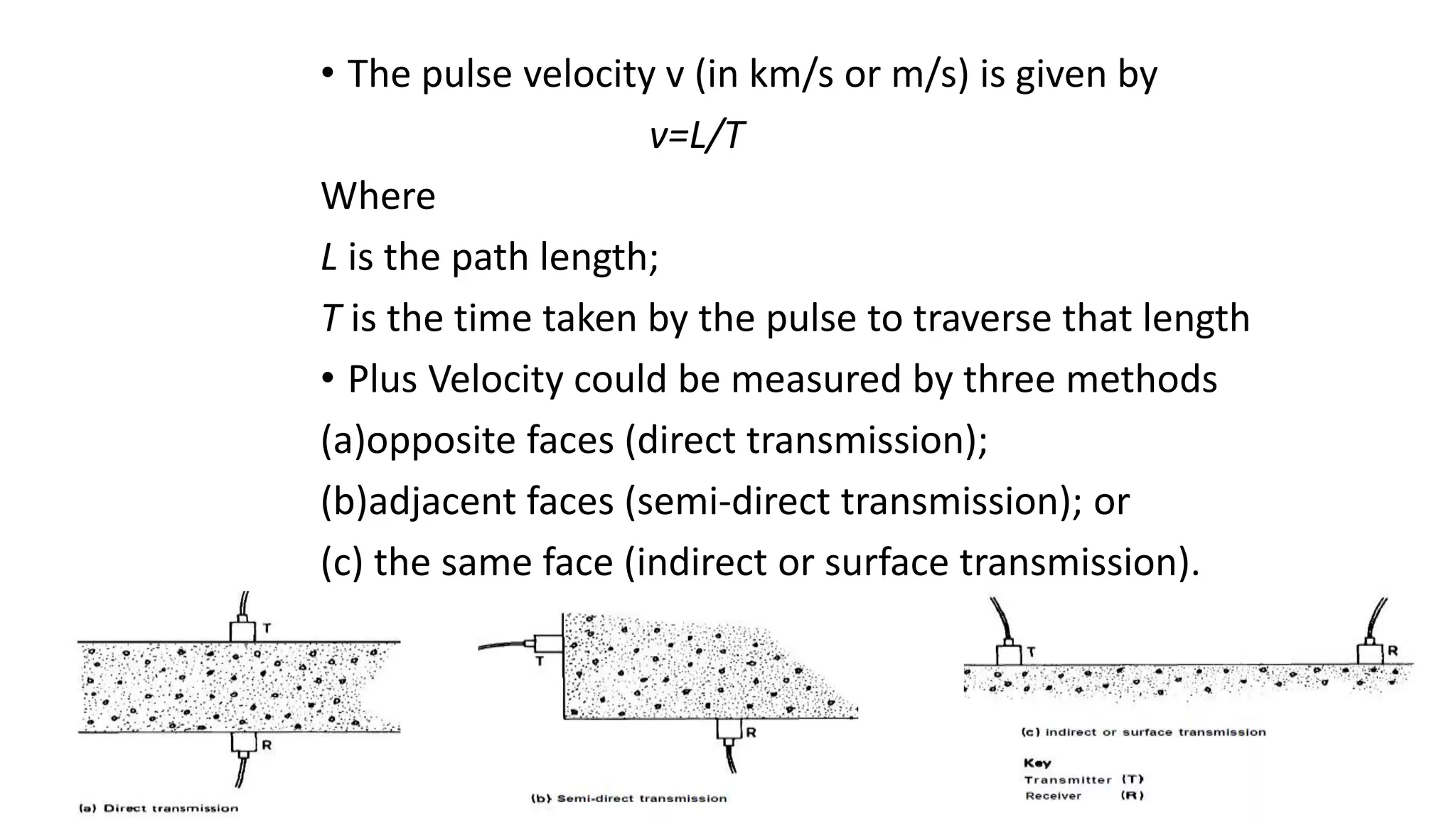
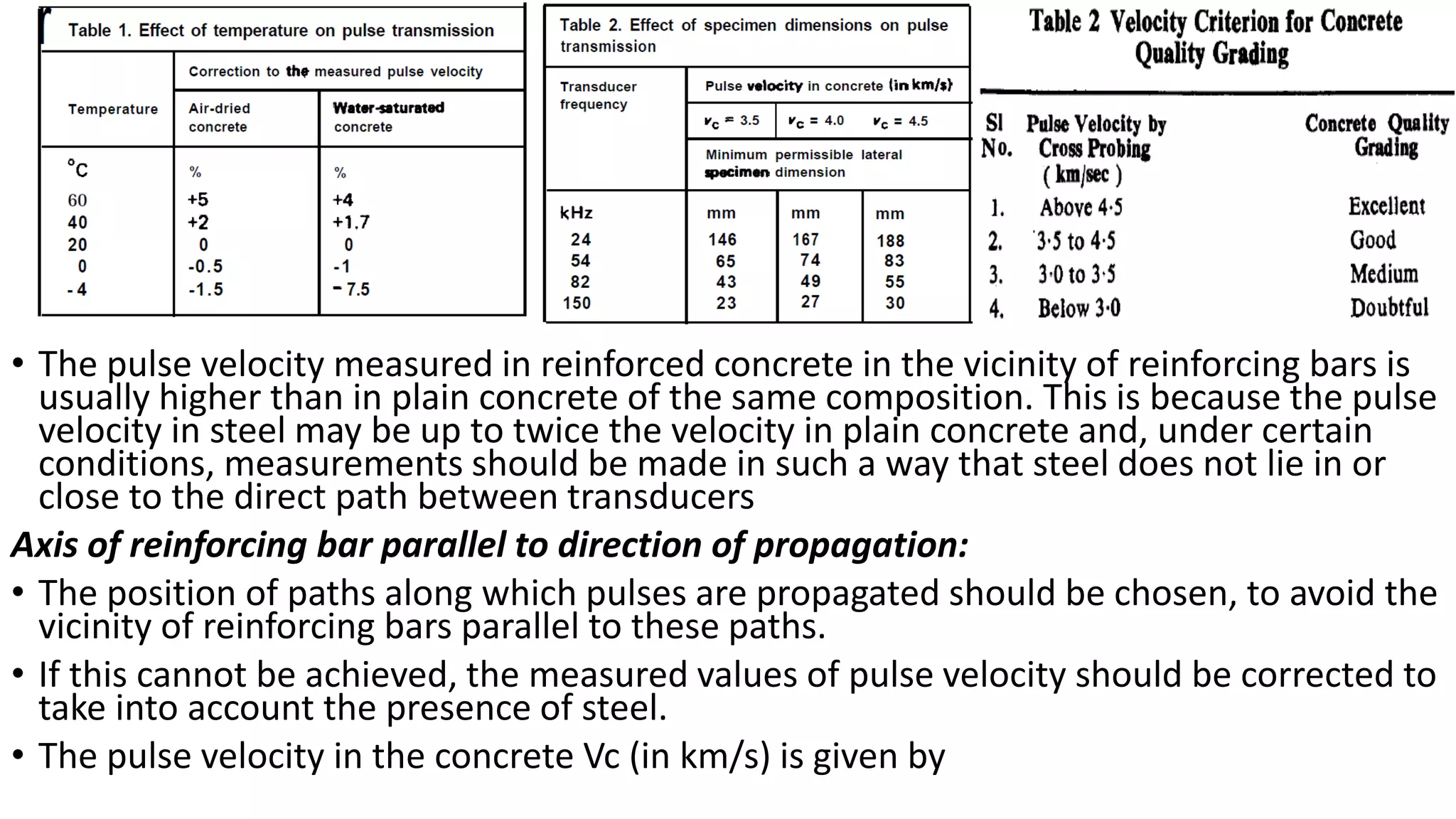
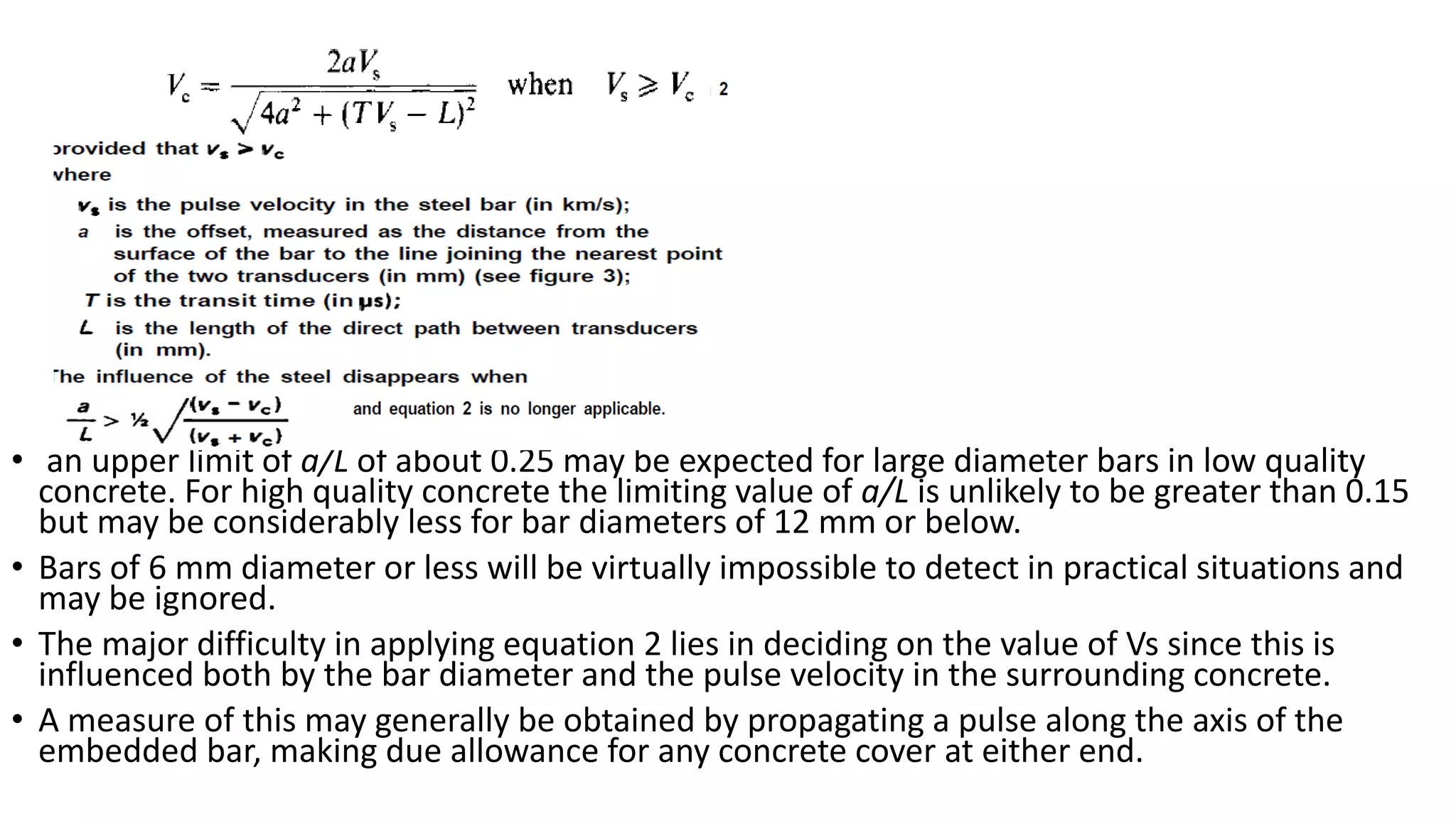
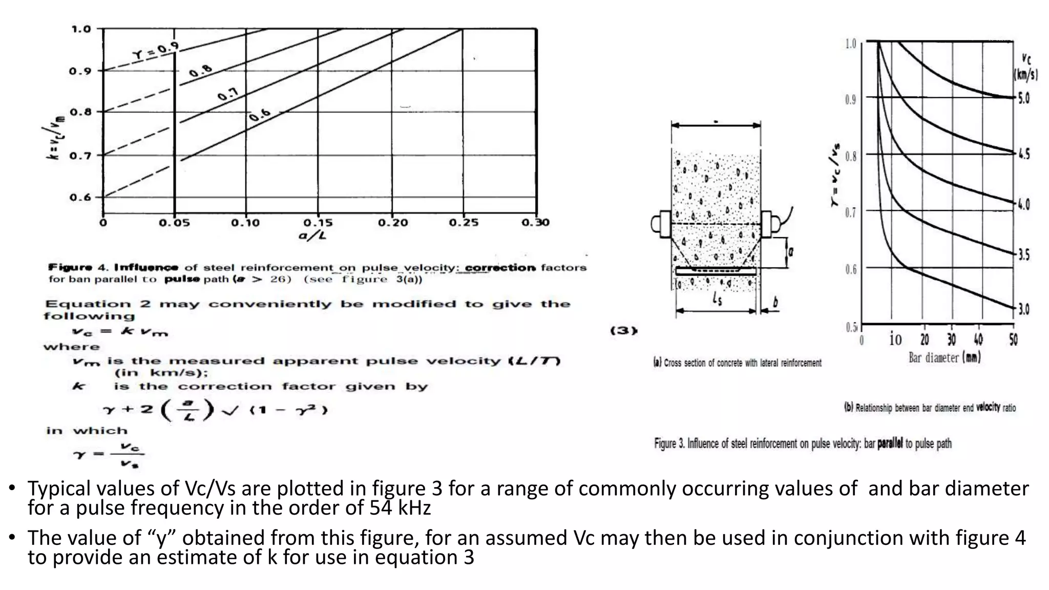
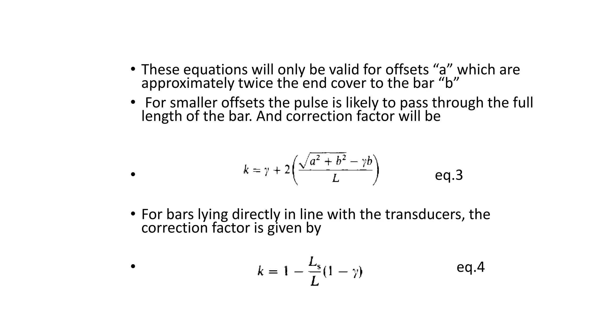
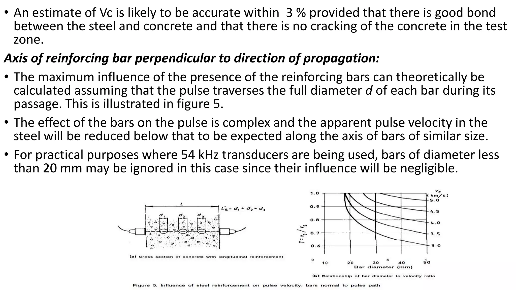
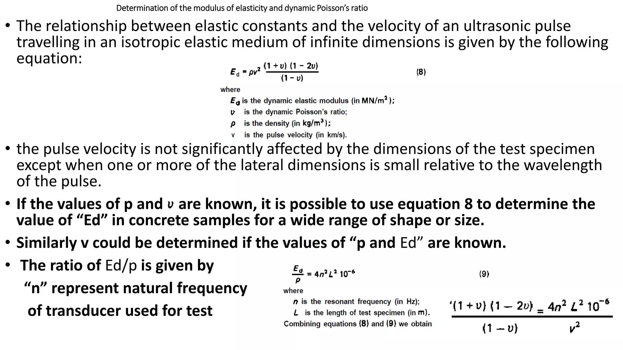
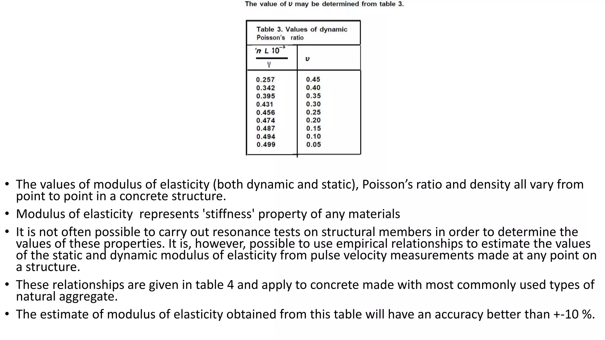
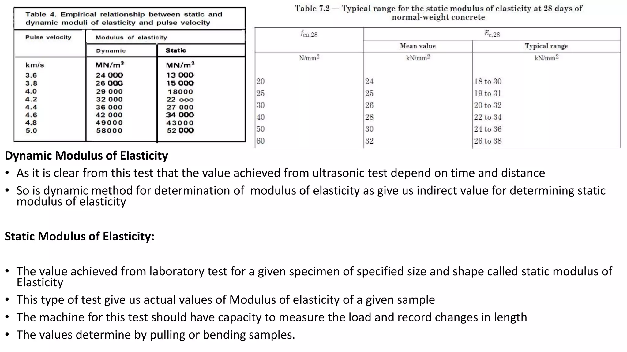
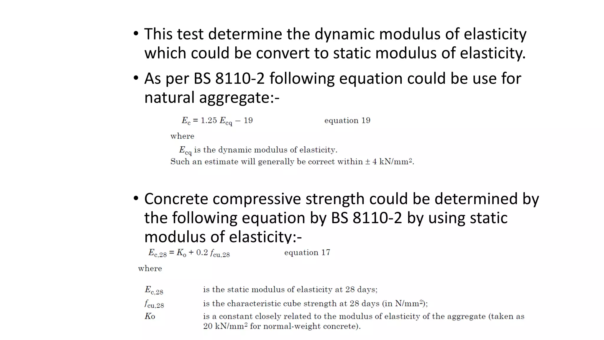
Ultrasonic test
• Shall be confirmed to BS 1881 Part 203
• There are two main component
• PUNDIT (Portable Ultrasonic Nondestructive Digital Indicating Tester) testing
machines are will known of this test.
• Transducers with natural frequencies between 20 kHz and 150 kHz are the most
suitable for use with concrete, employing pulses in the frequency range of 20–
150 kHz
• 54 kHz and 82 kHz will normally be used for site or laboratory testing of concrete,
although frequencies as low as 10 kHz may be used for very long path lengths
and at the other extreme, frequencies up to 1 MHz for mortars and grouts
A)transit time: Time taken for an ultrasonic pulse to travel from the transmitting
transducer to the receiving transducer, passing through the interposed concrete.
B.) onset: Leading edge of the pulse detected by the measuring apparatus.
Purpose:
• determine the uniformity of concrete in or between members
• detect the presence and approximate extent of cracks & voids
• measured changes occurring with time in the properties of the concrete
• correlation of pulse velocity and strength as a measure of concrete quality
• determine modulus of elasticity and dynamic Poisson’s ratio(lateral or vertical
strain/ longitudinal horizontal strain) of the concrete
• A pulse of longitudinal vibrations is produced by an electro-acoustical transducer
which is held in contact with one surface of the concrete under test. After
traversing a known path length L in the concrete, the pulse of vibrations is
converted into an electrical signal by a second transducer.
• The pulse velocity v (in km/s or m/s) is given by
v=L/T
Where
L is the path length;
T is the time taken by the pulse to traverse that length
• Plus Velocity could be measured by three methods
(a)opposite faces (direct transmission);
(b)adjacent faces (semi-direct transmission); or
(c) the same face (indirect or surface transmission).
•For concrete surfaces, the finish is sufficiently smooth to
ensure good acoustical contact by the use of a “coupling
medium” and by pressing the transducer against the concrete
surface.
•Typical couplants are petroleum jelly, grease, soft soap and
kaolin/glycerol paste.
•The path length over which the pulse velocity is measured
should be long enough, path length should be 100 mm for
concrete in which the nominal maximum size of aggregate is 20
mm or less and 150 mm for concrete in which the nominal
maximum size of aggregate is between 20 mm and 40 mm.
•The pulse velocity is not generally influenced by changes in
path length although the electronic timing apparatus may
indicate a tendency for velocity to reduce slightly with
increasing path length
•Avoid trowel surfaces, Select the smooth and level surfaces
•The velocity of short pulses of vibrations is independent of the
size and shape of specimen in which they travel, unless it’s
least lateral dimension is less than a specified minimum value.
•Table 2 gives the relationship between the pulse velocity in the
concrete, the transducer frequency and the minimum
permissible lateral dimension of the specimen.
• The pulse velocity measured in reinforced concrete in the vicinity of reinforcing bars is
usually higher than in plain concrete of the same composition. This is because the pulse
velocity in steel may be up to twice the velocity in plain concrete and, under certain
conditions, measurements should be made in such a way that steel does not lie in or
close to the direct path between transducers
Axis of reinforcing bar parallel to direction of propagation:
• The position of paths along which pulses are propagated should be chosen, to avoid the
vicinity of reinforcing bars parallel to these paths.
• If this cannot be achieved, the measured values of pulse velocity should be corrected to
take into account the presence of steel.
• The pulse velocity in the concrete Vc (in km/s) is given by
• an upper limit of a/L of about 0.25 may be expected for large diameter bars in low quality
concrete. For high quality concrete the limiting value of a/L is unlikely to be greater than 0.15
but may be considerably less for bar diameters of 12 mm or below.
• Bars of 6 mm diameter or less will be virtually impossible to detect in practical situations and
may be ignored.
• The major difficulty in applying equation 2 lies in deciding on the value of Vs since this is
influenced both by the bar diameter and the pulse velocity in the surrounding concrete.
• A measure of this may generally be obtained by propagating a pulse along the axis of the
embedded bar, making due allowance for any concrete cover at either end.
• Typical values of Vc/Vs are plotted in figure 3 for a range of commonly occurring values of and bar diameter
for a pulse frequency in the order of 54 kHz
• The value of “y” obtained from this figure, for an assumed Vc may then be used in conjunction with figure 4
to provide an estimate of k for use in equation 3
• These equations will only be valid for offsets “a” which are
approximately twice the end cover to the bar “b”
• For smaller offsets the pulse is likely to pass through the full
length of the bar. And correction factor will be
• eq.3
• For bars lying directly in line with the transducers, the
correction factor is given by
• eq.4
• An estimate of Vc is likely to be accurate within 3 % provided that there is good bond
between the steel and concrete and that there is no cracking of the concrete in the test
zone.
Axis of reinforcing bar perpendicular to direction of propagation:
• The maximum influence of the presence of the reinforcing bars can theoretically be
calculated assuming that the pulse traverses the full diameter d of each bar during its
passage. This is illustrated in figure 5.
• The effect of the bars on the pulse is complex and the apparent pulse velocity in the
steel will be reduced below that to be expected along the axis of bars of similar size.
• For practical purposes where 54 kHz transducers are being used, bars of diameter less
than 20 mm may be ignored in this case since their influence will be negligible.
• An estimate of the average influence of bar can be obtained for well
bonded bars of between 20 mm and 50 mm diameter by considering them
as equivalent longitudinal bars of total path length L’, (see figure 5).
• The bars lying directly in line with the transducers (see equation 4) may be
used for this purpose in conjunction with the value of “y” determined from
figure 5 which takes account of the reduced velocity in the steel.
• The influence of transverse steel will be reduced by bond deficiencies, and
is difficult to assess with any degree of accuracy if the bars do not lie
directly in line with the path between transducers,
Determination of concrete uniformity
• Heterogeneities in the concrete within or between members cause variations in pulse
velocity which, in turn, are related to variations in quality.
• Measurements of pulse velocity provide means of studying the homogeneity and, for
this purpose, a system of measuring points which covers uniformly the appropriate
volume of concrete in the structure has to be chosen.
• In a large unit of fairly uniform concrete, testing on a 1 m grid is usually adequate but,
on small units or variable concrete, a finer grid may be necessary.
• It should be noted that, in cases where the path length is the same throughout the
survey, the measured time may be used to assess the concrete uniformity without the
need to convert it to a velocity.
• This technique is particularly suitable for surveys where all the measurements are made
by indirect transmission.
• It is possible to express homogeneity in the form of a statistical parameter such as the
standard deviation or coefficient of variation of the pulse velocity measurements made
over the grid.
• However, such parameters can only be properly used to compare variations in concrete
units of broadly similar dimensions.
• Variations in pulse velocity are influenced by magnitude of the path length
because this determines the effective size of concrete sample which is under
examination during each measurement.
• The importance of variations should be judged in relation to the effect which they
can be expected to have on the required performance of the structural member
being tested.
• This generally means that the tolerance allowed for quality distribution within
members should be related either to the stress distribution within them under
critical working load conditions or to exposure conditions.
• When an ultrasonic pulse travelling through concrete meets a concrete-air
interface, there is negligible transmission of energy across this interface
• Thus, any air-filled crack or void lying immediately between two transducers will
obstruct the direct ultrasonic beam when the projected length of the void is
greater than the width of the transducers and the wavelength of sound used.
• When this happens, the transit time will be longer than in similar concrete with
no defect.
• It is possible to make use of this effect for locating flaws, voids or other defects
greater than about 100 mm in diameter or depth
• In cracked members, where the broken faces of the members are held tightly
together in close contact by compression forces, the pulse energy may pass
unimpeded across the crack.
Determination of Defects in concrete
Detecting large voids or cavities:
• A grid should be drawn on the concrete member with its points of intersection spaced
to correspond to the size of void that would significantly affect its performance.
• A survey of measurements at the grid points enables a large cavity to be investigated by
measuring the transit times of pulses passing between the transducers when they are
placed so that the cavity lies in the direct path between them.
Estimating the depth of a surface crack
• Estimating the depth of a surface crack An estimate of the depth of a crack visible at the
surface may be obtained by measuring the transit times across the crack for two
different arrangements of the transducers placed on the surface.
• One suitable arrangement is shown in figure 6(a) in which the transmitting and
receiving transducers are placed at a distance x on opposite sides of the crack and
equidistant from it.
• Two values of x are chosen and transit times corresponding to these are measured;
convenient values of x are 150 mm and 300 mm.
• If these values are used, the depth of the air-filled crack C (in mm) is given by:
• A check may be made to assess whether or not the crack is lying in a plane
perpendicular to the surface by placing both transducers near to the crack (as shown in
figure 6(b)) and moving each in turn away from the crack.
• If a decrease in in transit time occurs when one transducer is moved, it indicates that
the crack slopes towards that transducer.
• OR the transmitting transducer is placed at a distance of 2.5y from the centre of the
crack and three readings of the transit time taken with the receiving transducer at
distances of y, 2y and 3y from the transmitter in the direction of the crack. (see figure
at next page)
• The transit times are plotted against distance as in figure 6(c) in which y is 150 mm.
• If the projection of the straight line through the points (y, T1 ) and (2y, T2) passes
through 0 there are no hidden cracks and the depth of the visible crack C (in mm) is
given by:
Estimating the thickness of a layer of inferior quality concrete
• Concrete may be suspected of having a surface layer of poor quality. This
may occur during manufacture or arise as a result of damage by fire, frost,
sulphate attack, etc.
• The thickness of such a layer of concrete can be estimated from ultrasonic
measurements of transit times along the surface.
• The procedure described in below should be used and the results plotted on
a graph as in figure 2.
• At the shorter distance of separation of the transducers, the pulse travels
through the surface layer and the slope of the experimental line gives the
pulse velocity in this surface layer.
• Beyond a certain distance of separation the first pulse to arrive has passed
along the surface of the underlying higher quality concrete and the slope of
these experimental points gives the velocity in that concrete.
• The distance x0 at which the change of slope occurs (see
figure 2) together with the measured pulse velocities in
the two different layers of concrete, enables an estimate
of the thickness t (in mm) of the surface layer to be made
as follows:
• The method is applicable to extensive surface areas in which the
inferior concrete forms a distinct layer of fairly uniform thickness
and when v, is appreciably smaller than v,. Localized areas of
damaged or honeycombed concrete are more difficult to test but it
is possible to derive an approximate thickness of such localized poor
quality material if both direct transmission and surface propagation
measurements are made.
• Changes occurring with time in the properties of concrete caused by the
hydration process, by the influence of environmental effects or by overloading,
may be determined by repeated measurements of pulse velocity at different
times with the same transducers in the same position.
• Measurements of changes in pulse velocity are usually indicative of changes in
strength and have the advantage that they can be made over progressive periods
of time on the same test piece throughout the investigation.
• Pulse velocity measurements are particularly useful for following the hardening
process, especially during the first 36 h. Here, rapid changes in pulse velocity are
associated with physiochemical changes in the cement paste structure and it is
desirable to make measurements at intervals of 1 h or 2 h if these changes are to
be followed closely.
• As the concrete hardens these intervals may be lengthened to 1 day or more
after the initial period of 36 h has elapsed.
Determination of the modulus of elasticity and dynamic Poisson’s ratio
• The relationship between elastic constants and the velocity of an ultrasonic pulse
travelling in an isotropic elastic medium of infinite dimensions is given by the following
equation:
• the pulse velocity is not significantly affected by the dimensions of the test specimen
except when one or more of the lateral dimensions is small relative to the wavelength
of the pulse.
• If the values of p and are known, it is possible to use equation 8 to determine the
value of “Ed” in concrete samples for a wide range of shape or size.
• Similarly v could be determined if the values of “p and Ed” are known.
• The ratio of Ed/p is given by
“n” represent natural frequency
of transducer used for test
• The values of modulus of elasticity (both dynamic and static), Poisson’s ratio and density all vary from
point to point in a concrete structure.
• Modulus of elasticity represents 'stiffness' property of any materials
• It is not often possible to carry out resonance tests on structural members in order to determine the
values of these properties. It is, however, possible to use empirical relationships to estimate the values
of the static and dynamic modulus of elasticity from pulse velocity measurements made at any point on
a structure.
• These relationships are given in table 4 and apply to concrete made with most commonly used types of
natural aggregate.
• The estimate of modulus of elasticity obtained from this table will have an accuracy better than +-10 %.
Dynamic Modulus of Elasticity
• As it is clear from this test that the value achieved from ultrasonic test depend on time and distance
• So is dynamic method for determination of modulus of elasticity as give us indirect value for determining static
modulus of elasticity
Static Modulus of Elasticity:
• The value achieved from laboratory test for a given specimen of specified size and shape called static modulus of
Elasticity
• This type of test give us actual values of Modulus of elasticity of a given sample
• The machine for this test should have capacity to measure the load and record changes in length
• The values determine by pulling or bending samples.
• This test determine the dynamic modulus of elasticity
which could be convert to static modulus of elasticity.
• As per BS 8110-2 following equation could be use for
natural aggregate:-
• Concrete compressive strength could be determined by
the following equation by BS 8110-2 by using static
modulus of elasticity:-

Ultrasonic pulse velocity test

  • 1.
    Ultrasonic test • Shallbe confirmed to BS 1881 Part 203 • There are two main component • PUNDIT (Portable Ultrasonic Nondestructive Digital Indicating Tester) testing machines are will known of this test. • Transducers with natural frequencies between 20 kHz and 150 kHz are the most suitable for use with concrete, employing pulses in the frequency range of 20– 150 kHz • 54 kHz and 82 kHz will normally be used for site or laboratory testing of concrete, although frequencies as low as 10 kHz may be used for very long path lengths and at the other extreme, frequencies up to 1 MHz for mortars and grouts A)transit time: Time taken for an ultrasonic pulse to travel from the transmitting transducer to the receiving transducer, passing through the interposed concrete.
  • 2.
    B.) onset: Leadingedge of the pulse detected by the measuring apparatus. Purpose: • determine the uniformity of concrete in or between members • detect the presence and approximate extent of cracks & voids • measured changes occurring with time in the properties of the concrete • correlation of pulse velocity and strength as a measure of concrete quality • determine modulus of elasticity and dynamic Poisson’s ratio(lateral or vertical strain/ longitudinal horizontal strain) of the concrete • A pulse of longitudinal vibrations is produced by an electro-acoustical transducer which is held in contact with one surface of the concrete under test. After traversing a known path length L in the concrete, the pulse of vibrations is converted into an electrical signal by a second transducer.
  • 3.
    • The pulsevelocity v (in km/s or m/s) is given by v=L/T Where L is the path length; T is the time taken by the pulse to traverse that length • Plus Velocity could be measured by three methods (a)opposite faces (direct transmission); (b)adjacent faces (semi-direct transmission); or (c) the same face (indirect or surface transmission).
  • 4.
    •For concrete surfaces,the finish is sufficiently smooth to ensure good acoustical contact by the use of a “coupling medium” and by pressing the transducer against the concrete surface. •Typical couplants are petroleum jelly, grease, soft soap and kaolin/glycerol paste. •The path length over which the pulse velocity is measured should be long enough, path length should be 100 mm for concrete in which the nominal maximum size of aggregate is 20 mm or less and 150 mm for concrete in which the nominal maximum size of aggregate is between 20 mm and 40 mm.
  • 5.
    •The pulse velocityis not generally influenced by changes in path length although the electronic timing apparatus may indicate a tendency for velocity to reduce slightly with increasing path length •Avoid trowel surfaces, Select the smooth and level surfaces •The velocity of short pulses of vibrations is independent of the size and shape of specimen in which they travel, unless it’s least lateral dimension is less than a specified minimum value. •Table 2 gives the relationship between the pulse velocity in the concrete, the transducer frequency and the minimum permissible lateral dimension of the specimen.
  • 6.
    • The pulsevelocity measured in reinforced concrete in the vicinity of reinforcing bars is usually higher than in plain concrete of the same composition. This is because the pulse velocity in steel may be up to twice the velocity in plain concrete and, under certain conditions, measurements should be made in such a way that steel does not lie in or close to the direct path between transducers Axis of reinforcing bar parallel to direction of propagation: • The position of paths along which pulses are propagated should be chosen, to avoid the vicinity of reinforcing bars parallel to these paths. • If this cannot be achieved, the measured values of pulse velocity should be corrected to take into account the presence of steel. • The pulse velocity in the concrete Vc (in km/s) is given by
  • 7.
    • an upperlimit of a/L of about 0.25 may be expected for large diameter bars in low quality concrete. For high quality concrete the limiting value of a/L is unlikely to be greater than 0.15 but may be considerably less for bar diameters of 12 mm or below. • Bars of 6 mm diameter or less will be virtually impossible to detect in practical situations and may be ignored. • The major difficulty in applying equation 2 lies in deciding on the value of Vs since this is influenced both by the bar diameter and the pulse velocity in the surrounding concrete. • A measure of this may generally be obtained by propagating a pulse along the axis of the embedded bar, making due allowance for any concrete cover at either end.
  • 8.
    • Typical valuesof Vc/Vs are plotted in figure 3 for a range of commonly occurring values of and bar diameter for a pulse frequency in the order of 54 kHz • The value of “y” obtained from this figure, for an assumed Vc may then be used in conjunction with figure 4 to provide an estimate of k for use in equation 3
  • 9.
    • These equationswill only be valid for offsets “a” which are approximately twice the end cover to the bar “b” • For smaller offsets the pulse is likely to pass through the full length of the bar. And correction factor will be • eq.3 • For bars lying directly in line with the transducers, the correction factor is given by • eq.4
  • 10.
    • An estimateof Vc is likely to be accurate within 3 % provided that there is good bond between the steel and concrete and that there is no cracking of the concrete in the test zone. Axis of reinforcing bar perpendicular to direction of propagation: • The maximum influence of the presence of the reinforcing bars can theoretically be calculated assuming that the pulse traverses the full diameter d of each bar during its passage. This is illustrated in figure 5. • The effect of the bars on the pulse is complex and the apparent pulse velocity in the steel will be reduced below that to be expected along the axis of bars of similar size. • For practical purposes where 54 kHz transducers are being used, bars of diameter less than 20 mm may be ignored in this case since their influence will be negligible.
  • 11.
    • An estimateof the average influence of bar can be obtained for well bonded bars of between 20 mm and 50 mm diameter by considering them as equivalent longitudinal bars of total path length L’, (see figure 5). • The bars lying directly in line with the transducers (see equation 4) may be used for this purpose in conjunction with the value of “y” determined from figure 5 which takes account of the reduced velocity in the steel. • The influence of transverse steel will be reduced by bond deficiencies, and is difficult to assess with any degree of accuracy if the bars do not lie directly in line with the path between transducers,
  • 12.
    Determination of concreteuniformity • Heterogeneities in the concrete within or between members cause variations in pulse velocity which, in turn, are related to variations in quality. • Measurements of pulse velocity provide means of studying the homogeneity and, for this purpose, a system of measuring points which covers uniformly the appropriate volume of concrete in the structure has to be chosen. • In a large unit of fairly uniform concrete, testing on a 1 m grid is usually adequate but, on small units or variable concrete, a finer grid may be necessary. • It should be noted that, in cases where the path length is the same throughout the survey, the measured time may be used to assess the concrete uniformity without the need to convert it to a velocity. • This technique is particularly suitable for surveys where all the measurements are made by indirect transmission. • It is possible to express homogeneity in the form of a statistical parameter such as the standard deviation or coefficient of variation of the pulse velocity measurements made over the grid. • However, such parameters can only be properly used to compare variations in concrete units of broadly similar dimensions.
  • 13.
    • Variations inpulse velocity are influenced by magnitude of the path length because this determines the effective size of concrete sample which is under examination during each measurement. • The importance of variations should be judged in relation to the effect which they can be expected to have on the required performance of the structural member being tested. • This generally means that the tolerance allowed for quality distribution within members should be related either to the stress distribution within them under critical working load conditions or to exposure conditions.
  • 14.
    • When anultrasonic pulse travelling through concrete meets a concrete-air interface, there is negligible transmission of energy across this interface • Thus, any air-filled crack or void lying immediately between two transducers will obstruct the direct ultrasonic beam when the projected length of the void is greater than the width of the transducers and the wavelength of sound used. • When this happens, the transit time will be longer than in similar concrete with no defect. • It is possible to make use of this effect for locating flaws, voids or other defects greater than about 100 mm in diameter or depth • In cracked members, where the broken faces of the members are held tightly together in close contact by compression forces, the pulse energy may pass unimpeded across the crack. Determination of Defects in concrete
  • 15.
    Detecting large voidsor cavities: • A grid should be drawn on the concrete member with its points of intersection spaced to correspond to the size of void that would significantly affect its performance. • A survey of measurements at the grid points enables a large cavity to be investigated by measuring the transit times of pulses passing between the transducers when they are placed so that the cavity lies in the direct path between them. Estimating the depth of a surface crack • Estimating the depth of a surface crack An estimate of the depth of a crack visible at the surface may be obtained by measuring the transit times across the crack for two different arrangements of the transducers placed on the surface. • One suitable arrangement is shown in figure 6(a) in which the transmitting and receiving transducers are placed at a distance x on opposite sides of the crack and equidistant from it. • Two values of x are chosen and transit times corresponding to these are measured; convenient values of x are 150 mm and 300 mm. • If these values are used, the depth of the air-filled crack C (in mm) is given by:
  • 16.
    • A checkmay be made to assess whether or not the crack is lying in a plane perpendicular to the surface by placing both transducers near to the crack (as shown in figure 6(b)) and moving each in turn away from the crack. • If a decrease in in transit time occurs when one transducer is moved, it indicates that the crack slopes towards that transducer. • OR the transmitting transducer is placed at a distance of 2.5y from the centre of the crack and three readings of the transit time taken with the receiving transducer at distances of y, 2y and 3y from the transmitter in the direction of the crack. (see figure at next page) • The transit times are plotted against distance as in figure 6(c) in which y is 150 mm. • If the projection of the straight line through the points (y, T1 ) and (2y, T2) passes through 0 there are no hidden cracks and the depth of the visible crack C (in mm) is given by:
  • 18.
    Estimating the thicknessof a layer of inferior quality concrete • Concrete may be suspected of having a surface layer of poor quality. This may occur during manufacture or arise as a result of damage by fire, frost, sulphate attack, etc. • The thickness of such a layer of concrete can be estimated from ultrasonic measurements of transit times along the surface. • The procedure described in below should be used and the results plotted on a graph as in figure 2. • At the shorter distance of separation of the transducers, the pulse travels through the surface layer and the slope of the experimental line gives the pulse velocity in this surface layer. • Beyond a certain distance of separation the first pulse to arrive has passed along the surface of the underlying higher quality concrete and the slope of these experimental points gives the velocity in that concrete.
  • 19.
    • The distancex0 at which the change of slope occurs (see figure 2) together with the measured pulse velocities in the two different layers of concrete, enables an estimate of the thickness t (in mm) of the surface layer to be made as follows:
  • 20.
    • The methodis applicable to extensive surface areas in which the inferior concrete forms a distinct layer of fairly uniform thickness and when v, is appreciably smaller than v,. Localized areas of damaged or honeycombed concrete are more difficult to test but it is possible to derive an approximate thickness of such localized poor quality material if both direct transmission and surface propagation measurements are made.
  • 21.
    • Changes occurringwith time in the properties of concrete caused by the hydration process, by the influence of environmental effects or by overloading, may be determined by repeated measurements of pulse velocity at different times with the same transducers in the same position. • Measurements of changes in pulse velocity are usually indicative of changes in strength and have the advantage that they can be made over progressive periods of time on the same test piece throughout the investigation. • Pulse velocity measurements are particularly useful for following the hardening process, especially during the first 36 h. Here, rapid changes in pulse velocity are associated with physiochemical changes in the cement paste structure and it is desirable to make measurements at intervals of 1 h or 2 h if these changes are to be followed closely. • As the concrete hardens these intervals may be lengthened to 1 day or more after the initial period of 36 h has elapsed.
  • 22.
    Determination of themodulus of elasticity and dynamic Poisson’s ratio • The relationship between elastic constants and the velocity of an ultrasonic pulse travelling in an isotropic elastic medium of infinite dimensions is given by the following equation: • the pulse velocity is not significantly affected by the dimensions of the test specimen except when one or more of the lateral dimensions is small relative to the wavelength of the pulse. • If the values of p and are known, it is possible to use equation 8 to determine the value of “Ed” in concrete samples for a wide range of shape or size. • Similarly v could be determined if the values of “p and Ed” are known. • The ratio of Ed/p is given by “n” represent natural frequency of transducer used for test
  • 23.
    • The valuesof modulus of elasticity (both dynamic and static), Poisson’s ratio and density all vary from point to point in a concrete structure. • Modulus of elasticity represents 'stiffness' property of any materials • It is not often possible to carry out resonance tests on structural members in order to determine the values of these properties. It is, however, possible to use empirical relationships to estimate the values of the static and dynamic modulus of elasticity from pulse velocity measurements made at any point on a structure. • These relationships are given in table 4 and apply to concrete made with most commonly used types of natural aggregate. • The estimate of modulus of elasticity obtained from this table will have an accuracy better than +-10 %.
  • 24.
    Dynamic Modulus ofElasticity • As it is clear from this test that the value achieved from ultrasonic test depend on time and distance • So is dynamic method for determination of modulus of elasticity as give us indirect value for determining static modulus of elasticity Static Modulus of Elasticity: • The value achieved from laboratory test for a given specimen of specified size and shape called static modulus of Elasticity • This type of test give us actual values of Modulus of elasticity of a given sample • The machine for this test should have capacity to measure the load and record changes in length • The values determine by pulling or bending samples.
  • 25.
    • This testdetermine the dynamic modulus of elasticity which could be convert to static modulus of elasticity. • As per BS 8110-2 following equation could be use for natural aggregate:- • Concrete compressive strength could be determined by the following equation by BS 8110-2 by using static modulus of elasticity:-