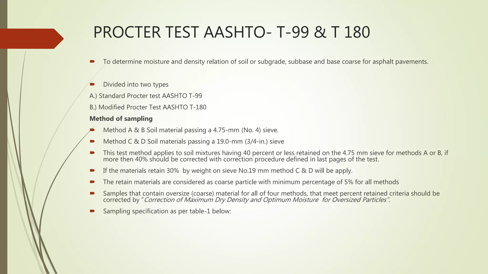
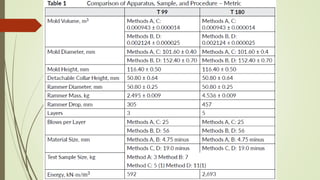
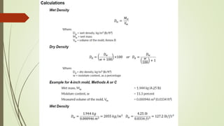
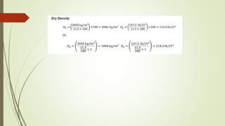
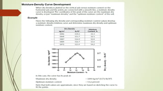
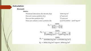
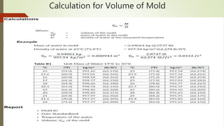
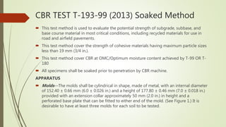
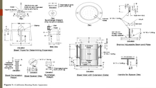
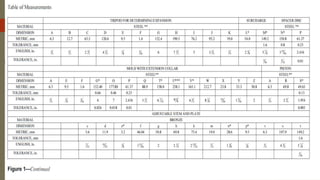
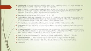
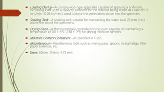
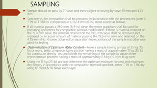
SlideShare a Scribd company logo
1 of 35
PROCTER TEST AASHTO- T-99 & T 180
 To determine moisture and density relation of soil or subgrade, subbase and base coarse for asphalt pavements.
 Divided into two types
A.) Standard Procter test AASHTO T-99
B.) Modified Procter Test AASHTO T-180
Method of sampling
 Method A & B Soil material passing a 4.75-mm (No. 4) sieve.
 Method C & D Soil materials passing a 19.0-mm (3/4-in.) sieve
 This test method applies to soil mixtures having 40 percent or less retained on the 4.75 mm sieve for methods A or B, if
more then 40% should be corrected with correction procedure defined in last pages of the test.
 If the materials retain 30% by weight on sieve No.19 mm method C & D will be apply.
 The retain materials are considered as coarse particle with minimum percentage of 5% for all methods
 Samples that contain oversize (coarse) material for all of four methods, that meet percent retained criteria should be
corrected by “Correction of Maximum Dry Density and Optimum Moisture for Oversized Particles”.
 Sampling specification as per table-1 below:
 Samples of soil or soil-aggregate mixture are prepared at several moisture contents and
compacted into molds of specified size and specified layers.
 The maximum wet density is determined by the appropriate moisture contents.
 Moisture contents of the compacted samples are determined and used to obtain the
dry density values of the same samples
Procedure:
 If the sample is damp, dry it until it becomes friable under a trowel. Drying may be in air
or by use of a drying apparatus maintained at a temperature not exceeding 60°C
 Thoroughly break up the soil samples or soil aggregate in a manner that avoids
reducing the natural size of individual particles.
 Obtain a representative test sample of the mass required by passing the material
through the sieve required See Table 1
 In instances where the material is prone to degradation, i.e., granular material, a
compaction sample with differing moisture contents should be prepared for each point.
 Note 2: If the sample is plastic (clay types), it should stand for a minimum of 12 hours
after the addition of water to allow the moisture to be absorbed. In this case, several
samples at different moisture contents should be prepared, put in sealed containers and
tested the next day.
 During compaction, rest the mold firmly on a dense, uniform, rigid, and stable foundation or
base. This base shall remain stationary during the compaction process.
 Determine the mass of the clean, dry mold. Include the base plate, but exclude the extension
collar. Record the mass to the nearest 1 g (0.005 lb).
 Thoroughly mix the selected representative sample with sufficient water to dampen it to
approximately 4 to 8 percentage points below optimum moisture content.
 See Note 2. For many materials, this condition can be identified by forming a cast by hand.
 Form a specimen by compacting the prepared soil in the mold assembly in approximately
equal layers. For each layer:
 a. Spread the loose material uniformly in the mold.
 Note 3: It is recommended to cover the remaining material with a nonabsorbent sheet or
damp cloth to minimize loss of moisture.
 b. Lightly tamp the loose material with the manual rammer or other similar device, this
establishes a firm surface.
 c. Compact each layer with uniformly distributed blows from the rammer. See Table 1 for mold
size, number of layers, number of blows, and rammer specification for the various test
methods.
 d. Trim down material that has not been compacted and remains adjacent to the walls of the
mold and extends above the compacted surface.
 4. Remove the extension collar. Avoid shearing off the sample below the top of the mold.
The material compacted in the mold should not be over 6 mm (¼ in) above the top of the
mold once the collar has been removed.
 5. Trim the compacted soil even with the top of the mold with the beveled side of the
straightedge.
 6. Determine and record the mass of the mold, base plate, and wet soil to the nearest 1 g
(0.005 lb) or better.
 7. Determine and record the wet mass (Mw) of the sample by subtracting the mass in Step 1
from the mass in Step 6.
 8. Calculate the wet density, in kg/m3 (lb/ft3), by dividing the wet mass by the measured
volume (Vm).
 9. Extrude the material from the mold. For soils and soil-aggregate mixtures, slice vertically
through the center and take a representative moisture content sample from one of the cut
faces, ensuring that all layers are represented. For granular materials, a vertical face will not
exist. Take a representative sample. This sample must meet the sample size requirements of
the test method used to determine moisture content.
 Note 4: When developing a curve for free-draining soils such as uniform sands and gravels,
gravels, where seepage occurs at the bottom of the mold and base plate, taking a
representative moisture content from the mixing bowl may be preferred in order to
determine the amount of moisture available for compaction.
 10. Determine and record the moisture content of the sample in accordance with
the FOP for AASHTO T 255/T 265.
 11. Thoroughly break up the remaining portion of the molded specimen until it will
again pass through the sieve, as judged by eye, and add to the remaining portion
of the sample being tested. See Note 2.
 12. Add sufficient water to increase the moisture content of the remaining soil by 1
to 2 percentage points and repeat steps 3 through 11.
 13. Continue determinations until there is either a decrease or no change in the wet
mass. There will be a minimum of three points on the dry side of the curve and two
points on the wet side. For non-cohesive, drainable soils, one point on the wet side
is sufficient.
Correction of MDD for Coarse Particles
 This section corrects the maximum dry density and moisture content of the material retained
on the 4.75 mm (No. 4) sieve, Methods A and B; or the material retained on the 19 mm (¾
in) sieve, Methods C and D.
 The maximum dry density, corrected for oversized particles and total moisture content, are
compared with the field-dry density and field moisture content.
 This method applies when more than 5 percent by weight of oversize particles is present.
 Bulk specific gravity (Gsb) of the oversized particles is required to determine the corrected
maximum dry density.
 Use the bulk specific gravity as determined using the FOP for AASHTO T 85 in the
calculations. For construction activities, a established value or specific gravity of 2.600 may be
used.
 This correction can also be applied to the sample obtained from the field while performing
in-place density.
 1. Use the sample from this procedure or a sample obtained according to the FOP
for AASHTO T 310.
 2. Sieve the sample on the 4.75 mm (No. 4) sieve for Methods A and B or the 19
mm (¾ in) sieve, Methods C and D.
To determine the dry mass of the fractions using moisture samples.
 1. Determine the moisture masses at OMC of both fractions, fine (MMf) and
oversized (MMc):
 2. Obtain moisture samples from the fine and oversized material at OMC/optimum
moisture content & determine OMC in %age.
Determine the dry mass of the oversized and fine fractions (MDC and MDF) by two
steps:
 a. Dry the fractions, fine and oversized, in air or by use of a drying apparatus that is
maintained at a temperature not exceeding 60ºC (140ºF).
 b. Calculate the dry masses of oversize and fine particles.
Calculation for Volume of Mold
CBR TEST T-193-99 (2013) Soaked Method
 This test method is used to evaluate the potential strength of subgrade, subbase, and
base course material in most critical conditions, including recycled materials for use in
road and airfield pavements.
 This test method cover the strength of cohesive materials having maximum particle sizes
less than 19 mm (3/4 in.).
 This test method cover CBR at OMC/Optimum moisture content achieved by T-99 OR T-
180
 All specimens shall be soaked prior to penetration by CBR machine.
APPARATUS
 Molds—The molds shall be cylindrical in shape, made of metal, with an internal diameter
of 152.40 ± 0.66 mm (6.0 ± 0.026 in.) and a height of 177.80 ± 0.46 mm (7.0 ± 0.018 in.)
provided with an extension collar approximately 50 mm (2.0 in.) in height and a
perforated base plate that can be fitted to either end of the mold. (See Figure 1.) It is
desirable to have at least three molds for each soil to be tested.
 Spacer Disk—A circular spacer disk made of metal 150.8 ± 0.8 mm (515/16 ± 1/32 in.) in diameter and
61.37 ± 0.25 mm (2.416 ± 0.01 in.) in height. (See Figure 1.)
 Note 1—When using molds having a height of 177.80 mm (7.0 in.) (Figure 1), a spacer disk height of
61.37 mm (2.416 in.) is needed to obtain a thickness of compacted specimen that conforms to the
thickness: 116.43 mm (4.584 in.) of specimens in T 99 and T 180.
 Rammer—A rammer as specified in either T 99 or T 180.
 Apparatus for Measuring Expansion—This consists of a swell plate with adjustable stem (Figure 1) and a
tripod support for a dial indicator (Figure 1). The swell plate is made of metal, 149.2 ± 1.6 mm (57/8 ±
in.) in diameter and is perforated with 1.6-mm (1/16-in.) diameter holes.
 The tripod used to support the dial indicator is arranged to fit the mold extension collar.
 Indicators—Two dial indicators: each indicator shall have a 25-mm (1-in.) throw and read to 0.02 mm
(0.001 in.).
 Surcharge Weights—One annular metal weight with a center hole approximately 54.0 mm (21/8 in.) in
diameter and several slotted or split metal weights, all 149.2 ± 1.6 mm (57/8 ± 1/16 in.) in diameter and
each having a mass of 2.27 ± 0.04 kg (5 ± 0.10 lb) (Figure 1) (Note 2).
 Note 2—When using split weights, the mass of the pair shall be 2.27 ± 0.04 kg (5 ± 0.10 lb).
 Penetration Piston—A metal piston of circular cross-section having a diameter of 49.63 ±
 0.13 mm (1.954 ± 0.005 in.) area = 1935 mm2 (3 in.2) and not less than 102 mm (4 in.) long.
 (See Figure 1.)
 Loading Device—A compression-type apparatus capable of applying a uniformly
increasing load up to a capacity sufficient for the material being tested at a rate of 1.3
mm/min. (0.05 in./min.), used to force the penetration piston into the specimen.
 Soaking Tank—A soaking tank suitable for maintaining the water level 25 mm (1 in.)
above the top of the specimens.
 Drying Oven—A thermostatically controlled drying oven capable of maintaining a
temperature of 110 ± 5ºC (230 ± 9ºF) for drying moisture samples.
 Moisture Content Containers—As specified in T 265.
 Miscellaneous—Miscellaneous tools such as mixing pans, spoons, straightedge, filter
paper, balances, etc.
 Sieve: 50mm, 19 mm, 4.75 mm
SAMPLING
 Sample should be pass by 2” sieve and then subject to sieving by sieve 19 mm and 4.75
mm
 Specimen(s) for compaction shall be prepared in accordance with the procedures given in
T 99 or T 180 for compaction in a 152.4-mm (6-in.) mold except as follows:
 If all material passes a 19.0-mm (3/4-in.) sieve, the entire gradation shall be used for
preparing specimens for compaction without modification. If there is material retained on
the 19.0-mm sieve, the material retained on the 19.0-mm sieve shall be removed and
replaced by an equal amount of material passing the 19.0-mm sieve and retained on the
4.75-mm (No. 4) sieve obtained by separation from portions of the sample not otherwise
used for testing.
 Determination of Optimum Water Content—From a sample having a mass of 35 kg (75
lb) or more, select a representative portion having a mass of approximately 11 kg (25 lb)
for a moisture density test and divide the remaining of the sample to obtain three
representative portions having a mass of approximately 6.8 kg (15 lb)or 8 kg each.
 Using the 11-kg (25-lb) portion determine the optimum moisture content and maximum
dry density in accordance with the compaction method specified, either T 99 or T 180 by
using 6” mold & 56 blows each layer.
PROCEDURE
 Normally, three specimens must be compacted so that their compacted densities range from
95 percent (or lower) to 100 percent (or higher) of the maximum dry density determined in T-99
OR T-180.
 Generally about 10, 30, and 65 blows per layer are suitable for compacting specimens 1, 2, and
3, respectively.
 More than 56 blows per layer are generally required to mold a CBR specimen to 100 percent of
the maximum dry density determined by T 99 (Method D); this is due to the sample for the
moisture-density test being reused, while the sample for the CBR specimen is mixed and
compacted only once.
 Clamp the mold to the base plate, attach the extension collar and weigh to the nearest 5 g (0.01
lb).
 Insert the spacer disk into the mold and place a coarse filter paper on top of the disk.
 Mix each of the three 6.8-kg (15-lb) at OMC
 Compact the Samples in three equal layer if maximum density was determined by T 99 or five
equal layers if maximum density was determined by T 180, to give a total compacted depth of
about 125 mm, give a compacted density of 95 percent or less of the maximum density.
 Determine the moisture content of the material being compacted at the beginning and end
of the compaction procedure (two samples). Each moisture sample shall have a mass of at
least 100 g for fine-grained soils and 500 g for coarse-grained soils
 Remove the extension collar, and using a straightedge, trim the compacted soil even with
the top of the mold. Surface irregularities should be patched with small-sized material.
 Remove the spacer disk, place a coarse filter paper on the perforated base plate, invert the
mold and compacted soil and place on the filter paper so the compacted soil is in contact
with the filter paper. Clamp the perforated base plate to the mold and attach the collar.
 Determine the mass of the mold and specimen to the nearest 5 g (0.01 lb).
 Compact the other two 6.8-kg (15-lb) portions in accordance with the procedure except
that an intermediate number of blows per layer should be used to compact the second
specimen and the highest number of blows per layer shall be used to compact the third
specimen.
SOAKING
 Place the swell plate with adjustable stem on the soil sample in the mold and apply
sufficient annular weights to produce an intensity of loading equal to the mass of the
subbase and base courses and surfacing above the tested material. The total mass shall
be a minimum of 4.54 kg. Additional mass shall be added in increments of 2.26 kg.
 Place the tripod with dial indicator on top of the mold and make an initial dial reading.
 Immerse the mold in water to allow free access of water to top and bottom of the
specimen. During soaking, maintain the water level in the mold and the soaking tank
approximately 25 mm (1 in.) above the top of the specimen. Soak the specimen 96
hours (four days).
 Note 7—A shorter immersion period (not less than 24 hours) may be used for soil-
aggregate materials that drain readily if tests show that the shorter period does not
affect the test results. For some clay soils, a soaking period greater than 4 days may be
required.
 At the end of 96 hours, make a final dial reading on the soaked specimens and
calculate the swell as a percentage of the initial sample length:
 Remove the specimens from the soaking tank, pour the water off the top and allow to
drain downward for 15 minutes. Care shall be taken not to disturb the surface of the
specimens during removal of the water. After draining, remove the surcharge weights
and perforated plates.
 Note 8—The mass of the specimens may be determined after draining when it is
desired to determine the average wet density of the soaked and drained material.
PENETRATION TEST
 Application of Surcharge—Place a surcharge of annular and slotted weights on the
specimens equal to that used during soaking. To prevent displacement of soft materials
into the hole of the surcharge weights, seat the penetration piston with a 44 N (10-lb)
load after one surcharge weight has been placed on the specimen. After seating the
penetration piston the remaining of the surcharge weights shall then be placed around
the piston.
 Seating Piston—Seat the penetration piston with a 44 N (10-lb) load, then set both the
penetration dial indicator and the load indicator to zero.
 Application of Load—Apply the loads to the penetration piston so the rate of penetration
is uniform at 1.3 mm (0.05 in.)/min. Record the load when the penetration is 0.64, 1.27,
1.91, 2.54, 3.81, 5.08, and 7.62 mm (0.025, 0.050, 0.075, 0.100, 0.150, 0.200, and 0.300 in.).
 Load readings at penetrations of 10.16 and 12.70 mm (0.400 and 0.500 in.) may be
obtained if desired.
 Note 9—The moisture content of the upper 25 mm (1 in.) may be determined after testing
testing if desired. Moisture samples shall weigh at least 100 g for fine-grained soils and
500 g for granular soils.
CALCULATIONS
 Stress-Strain Curve—Plot the stress-strain (resistance to penetration-depth of
penetration) curve for each specimen as shown in Figure 2. In some instances, the initial
penetration takes place without a proportional increase in the resistance to penetration
and the curve may be concave upward. To obtain the true stress-strain relationships,
correct the curve having concave upward shape near the origin by adjusting the location
of the origin by extending the straightline portion of the stress-strain curve downward
until it intersects the abscissa. (See dashed lines.)Figure 2—
 California Bearing Ratio—The corrected load values shall be determined for each specimen at 2.54
and 5.08 mm (0.10 and 0.20 in.) penetration.
 California Bearing Ratio values are obtained in percent by dividing the corrected load values at
2.54 and 5.08 mm (0.10 and 0.20 in.) by the standard loads of 6.9 and 10.3 MPa (1000 and 1500
psi), respectively, and multiplying these ratios by 100.
 The CBR is generally selected at 2.54 mm (0.10 in.) penetration. If the ratio at 5.08 mm (0.20 in.)
penetration is greater, the test shall be rerun. If the check test gives a similar result, the ratio at
5.08 mm (0.20 in.) penetration shall be used.
 Design CBR for One Water Content Only—Using the data obtained from the three specimens,
plot the CBR-Dry Density as Molded relation as shown in Figure 3. The design CBR may then be
determined at the desired percentage of the maximum dry density, normally the minimum
percentage compaction permitted by the agency’s compaction specifications
Example from field testing laboratory
SCETION Sample No. Date CBR Soaked 17/01/2013
Lab. No. Source Date CBR Crushed 21/01/2013
Material SUB BASE Layer Nos. Ring Fector 1.42
Location Chainage Area of plunger 19.35 cm2
DENSITY Moisture % AASHTO T-180 SWELL
No. of Blows 10 Blows 30 Blows 65 Blows No. of Blows 56 56 56 Blows 10 30 65
Mould No. G R H CAN # E R T B4 B5 B6 Gauge used
Soil +Mould 11159 11440 11682 Wet Soil +CAN 406 468 368 initial
Mould wt. 6485 6490 6450 Dry Soil +CAN 384 442 348 24hrs
Soil wt. 4674 4950 5232 wt of water 22 26 20 48hrs
vol. of Mould 2103 2104 2095 CAN WT. 39 41 36 72hrs
wet Density 2.223 2.353 2.497 Dry Soil 345 401 312 96hrs
Moisture % 6.4 6.4 6.4 Moisture % 6.4 6.4 6.4 Swell
Dry Density 2.089 2.211 2.347 2.33 2.33 2.33 Specimen thickness 116.4
STANDARD LOAD 0.1" 70.3 0.2" 105.5 Swell %
CRUSHING CBR 10 Blows 30 Blows 65 Blows
PENETRATION
MM
PENETRA-
TION
INCH
DIAL
READING
LOAD
Kg
Unit
Load Kg/cm2
CBR
%
DIAL
READING
LOAD
Kg
Unit
Load
Kg/cm2
CBR
%
DIAL
READING
LOAD
Kg
Unit
Load Kg/cm2
CBR
%
0 0 0 0 0 0 0 0 0 0 0
0.635 0.025 95 170 9 155 220 11 300 252 13
1.27 0.050 195 399 21 300 426 22 500 710 37
1.91 0.075 255 375 19 410 582 30 690 980 51
2.54 0.100 330 515 27 38 500 710 37 52 810 1150 59 85
3.18 0.125 440 610 32 645 916 47 900 1278 66
3.81 0.150 510 719 37 680 966 50 1020 1448 75
4.45 0.175 570 799 41 750 1065 55 1100 1562 81
5.08 0.200 600 930 48 46 810 1150 59 56 1130 1605 83 79
6.35 0.250 680 950 49 840 1193 62 1160 1647 85
7.62 0.300
8.89 0.350
10.16 0.400
Load verses penetration for 10 blows specimen
0, 0
0.635, 9
1.27, 21
1.91, 19
2.54, 27
3.18, 32
3.81, 37
4.45, 41
5.08, 48
6.35, 49
0
10
20
30
40
50
60
0 2 4 6 8 10 12
PENETRATION IN MM
LOADINkg/cm2
Load verses penetration for 30 blows specimen
0
11
22
30
37
47
50
55
59
62
0
10
20
30
40
50
60
70
0 1 2 3 4 5 6 7
PENETRATION IN MM
LOADINkg/cm2
Load verses penetration for 65 blows specimen
0, 0
0.635, 13
1.27, 37
1.91, 51
2.54, 59
3.18, 66
3.81, 75
4.45, 81
5.08, 83
6.35, 85
0
10
20
30
40
50
60
70
80
90
0 1 2 3 4 5 6 7
PENETRATION IN MM
LOADINkg/cm2
PROCTOR MODIFIED
M.D.D 2.330
O.M.C 6.4
NO. OF BLOWS 10 30 65
DRY DENSITY
gm/cc 2.089 2.211 2.347
C.B.R. at 0.2" 46 56 79
C.B.R. at
Compaction Dry Density CBR%
98 2.283 67 30
45
60
75
90
105
120
2.050 2.150 2.250 2.350

More Related Content

What's hot

determination of flakiness index test.
determination of flakiness index test. determination of flakiness index test.
determination of flakiness index test. YASMINE HASLAN
 
Field density test
Field density testField density test
Field density testEngrMahmud3
 
SPECIFIC GRAVITY TEST ON BITUMINOUS MATERIALS.
SPECIFIC GRAVITY TEST ON BITUMINOUS MATERIALS.SPECIFIC GRAVITY TEST ON BITUMINOUS MATERIALS.
SPECIFIC GRAVITY TEST ON BITUMINOUS MATERIALS.Sayed Sajid H.Zidani
 
PENETRATION TEST ON BITUMINOUS MATERIALS.
PENETRATION TEST ON BITUMINOUS MATERIALS.PENETRATION TEST ON BITUMINOUS MATERIALS.
PENETRATION TEST ON BITUMINOUS MATERIALS.Sayed Sajid H.Zidani
 
Discharge Over a Vee-Notch Weir | Jameel Academy
Discharge Over a Vee-Notch Weir | Jameel AcademyDischarge Over a Vee-Notch Weir | Jameel Academy
Discharge Over a Vee-Notch Weir | Jameel AcademyJameel Academy
 
Permeability test
Permeability testPermeability test
Permeability testRaz Azad
 
Specific gravity of Coarse aggregate
Specific gravity of Coarse  aggregateSpecific gravity of Coarse  aggregate
Specific gravity of Coarse aggregateSarchia Khursheed
 
sampling and testing of aggregates
sampling and testing of aggregatessampling and testing of aggregates
sampling and testing of aggregatesjairam131
 
Proktor compaction
Proktor compactionProktor compaction
Proktor compactionNatalie Ulza
 
Chapter 3 classification
Chapter 3 classificationChapter 3 classification
Chapter 3 classificationGokul Saud
 
Sieve analysis of fine aggregates student experiment
Sieve analysis of fine aggregates student experimentSieve analysis of fine aggregates student experiment
Sieve analysis of fine aggregates student experimentkolveasna
 
Laboratory soil compaction test
Laboratory soil compaction testLaboratory soil compaction test
Laboratory soil compaction testAtul Hajong
 
Hot bituminous mix design
Hot bituminous mix designHot bituminous mix design
Hot bituminous mix designPriyansh Singh
 
Chapter 4 earth work and quantities new
Chapter 4 earth work and quantities newChapter 4 earth work and quantities new
Chapter 4 earth work and quantities newBashaFayissa1
 
California bearingratio test
California bearingratio testCalifornia bearingratio test
California bearingratio testAsok999
 
Proctor compaction test
Proctor compaction testProctor compaction test
Proctor compaction testKHK karimi
 
Geotechnical Engineering-I [Lec #21: Consolidation Problems]
Geotechnical Engineering-I [Lec #21: Consolidation Problems]Geotechnical Engineering-I [Lec #21: Consolidation Problems]
Geotechnical Engineering-I [Lec #21: Consolidation Problems]Muhammad Irfan
 

What's hot (20)

determination of flakiness index test.
determination of flakiness index test. determination of flakiness index test.
determination of flakiness index test.
 
Atterberg limits test
Atterberg limits testAtterberg limits test
Atterberg limits test
 
Field density test
Field density testField density test
Field density test
 
SPECIFIC GRAVITY TEST ON BITUMINOUS MATERIALS.
SPECIFIC GRAVITY TEST ON BITUMINOUS MATERIALS.SPECIFIC GRAVITY TEST ON BITUMINOUS MATERIALS.
SPECIFIC GRAVITY TEST ON BITUMINOUS MATERIALS.
 
PENETRATION TEST ON BITUMINOUS MATERIALS.
PENETRATION TEST ON BITUMINOUS MATERIALS.PENETRATION TEST ON BITUMINOUS MATERIALS.
PENETRATION TEST ON BITUMINOUS MATERIALS.
 
Discharge Over a Vee-Notch Weir | Jameel Academy
Discharge Over a Vee-Notch Weir | Jameel AcademyDischarge Over a Vee-Notch Weir | Jameel Academy
Discharge Over a Vee-Notch Weir | Jameel Academy
 
Permeability test
Permeability testPermeability test
Permeability test
 
Specific gravity of Coarse aggregate
Specific gravity of Coarse  aggregateSpecific gravity of Coarse  aggregate
Specific gravity of Coarse aggregate
 
sampling and testing of aggregates
sampling and testing of aggregatessampling and testing of aggregates
sampling and testing of aggregates
 
Proktor compaction
Proktor compactionProktor compaction
Proktor compaction
 
Chapter 3 classification
Chapter 3 classificationChapter 3 classification
Chapter 3 classification
 
Sieve analysis of fine aggregates student experiment
Sieve analysis of fine aggregates student experimentSieve analysis of fine aggregates student experiment
Sieve analysis of fine aggregates student experiment
 
Laboratory soil compaction test
Laboratory soil compaction testLaboratory soil compaction test
Laboratory soil compaction test
 
Hot bituminous mix design
Hot bituminous mix designHot bituminous mix design
Hot bituminous mix design
 
Chapter 4 earth work and quantities new
Chapter 4 earth work and quantities newChapter 4 earth work and quantities new
Chapter 4 earth work and quantities new
 
3) sampling
3) sampling3) sampling
3) sampling
 
Trixial test
Trixial testTrixial test
Trixial test
 
California bearingratio test
California bearingratio testCalifornia bearingratio test
California bearingratio test
 
Proctor compaction test
Proctor compaction testProctor compaction test
Proctor compaction test
 
Geotechnical Engineering-I [Lec #21: Consolidation Problems]
Geotechnical Engineering-I [Lec #21: Consolidation Problems]Geotechnical Engineering-I [Lec #21: Consolidation Problems]
Geotechnical Engineering-I [Lec #21: Consolidation Problems]
 

Similar to Cbr aashto t193 plus proctor t180

Bearing ratio capacity of compacted soil
Bearing ratio capacity of compacted soilBearing ratio capacity of compacted soil
Bearing ratio capacity of compacted soilameresmail92
 
Construction of High Speed Highway and Test track
Construction of High Speed Highway and Test trackConstruction of High Speed Highway and Test track
Construction of High Speed Highway and Test trackNikhil Kumar
 
Ex 8 standard proctor test
Ex 8 standard proctor testEx 8 standard proctor test
Ex 8 standard proctor testbhimaji40
 
Soil Test and Surveys
Soil Test and SurveysSoil Test and Surveys
Soil Test and SurveysJerome Jaime
 
Subgrade soil test, by Micotol
Subgrade soil test, by MicotolSubgrade soil test, by Micotol
Subgrade soil test, by MicotolMicotol
 
Proctor Compaction Test: A Basic Guide
Proctor Compaction Test: A Basic GuideProctor Compaction Test: A Basic Guide
Proctor Compaction Test: A Basic GuideCatie Ewen
 
Quality control lab
Quality control labQuality control lab
Quality control labRaja Katoch
 
FEFCO Testing methods (1).pdf
FEFCO Testing methods (1).pdfFEFCO Testing methods (1).pdf
FEFCO Testing methods (1).pdfDjfioryYonutz
 
Bursting Strength ISO 13938-2 (Part-II)
Bursting Strength ISO 13938-2 (Part-II)  Bursting Strength ISO 13938-2 (Part-II)
Bursting Strength ISO 13938-2 (Part-II) Shaharia Ahmed
 
3sampling-160110105028.pdf
3sampling-160110105028.pdf3sampling-160110105028.pdf
3sampling-160110105028.pdfHammadFarooq28
 

Similar to Cbr aashto t193 plus proctor t180 (20)

upe T99180
upe T99180upe T99180
upe T99180
 
Bearing ratio capacity of compacted soil
Bearing ratio capacity of compacted soilBearing ratio capacity of compacted soil
Bearing ratio capacity of compacted soil
 
Construction of High Speed Highway and Test track
Construction of High Speed Highway and Test trackConstruction of High Speed Highway and Test track
Construction of High Speed Highway and Test track
 
Ex 8 standard proctor test
Ex 8 standard proctor testEx 8 standard proctor test
Ex 8 standard proctor test
 
TEST OF CONCRETE
TEST OF CONCRETETEST OF CONCRETE
TEST OF CONCRETE
 
Soil Test and Surveys
Soil Test and SurveysSoil Test and Surveys
Soil Test and Surveys
 
Material 2
Material 2Material 2
Material 2
 
Subgrade soil test, by Micotol
Subgrade soil test, by MicotolSubgrade soil test, by Micotol
Subgrade soil test, by Micotol
 
Cbr test
Cbr testCbr test
Cbr test
 
Cbr test
Cbr testCbr test
Cbr test
 
Proctor Compaction Test: A Basic Guide
Proctor Compaction Test: A Basic GuideProctor Compaction Test: A Basic Guide
Proctor Compaction Test: A Basic Guide
 
Aashto t 87 80
Aashto t 87 80Aashto t 87 80
Aashto t 87 80
 
Quality control lab
Quality control labQuality control lab
Quality control lab
 
Test for sand
Test for sandTest for sand
Test for sand
 
ASTM D5030.pdf
ASTM D5030.pdfASTM D5030.pdf
ASTM D5030.pdf
 
FEFCO Testing methods (1).pdf
FEFCO Testing methods (1).pdfFEFCO Testing methods (1).pdf
FEFCO Testing methods (1).pdf
 
Bursting Strength ISO 13938-2 (Part-II)
Bursting Strength ISO 13938-2 (Part-II)  Bursting Strength ISO 13938-2 (Part-II)
Bursting Strength ISO 13938-2 (Part-II)
 
ASTM D1557.pdf
ASTM D1557.pdfASTM D1557.pdf
ASTM D1557.pdf
 
3sampling-160110105028.pdf
3sampling-160110105028.pdf3sampling-160110105028.pdf
3sampling-160110105028.pdf
 
CT-233 SOIL MECHANICS LAB MANUAL BSC Civil
CT-233 SOIL MECHANICS LAB MANUAL BSC Civil CT-233 SOIL MECHANICS LAB MANUAL BSC Civil
CT-233 SOIL MECHANICS LAB MANUAL BSC Civil
 

More from Ayaz khan

Quality tests for aggregates and concrete mix design
Quality tests for aggregates and concrete mix designQuality tests for aggregates and concrete mix design
Quality tests for aggregates and concrete mix designAyaz khan
 
Cement properties & Types
Cement properties & TypesCement properties & Types
Cement properties & TypesAyaz khan
 
Aggregates introduction, types and properties
Aggregates introduction, types and propertiesAggregates introduction, types and properties
Aggregates introduction, types and propertiesAyaz khan
 
Alkali reaction in concrete
Alkali reaction in concreteAlkali reaction in concrete
Alkali reaction in concreteAyaz khan
 
Cement properties and types
Cement properties and types Cement properties and types
Cement properties and types Ayaz khan
 
Ultrasonic pulse velocity test
Ultrasonic pulse velocity testUltrasonic pulse velocity test
Ultrasonic pulse velocity testAyaz khan
 
Pull out test for concrete
Pull out test for concretePull out test for concrete
Pull out test for concreteAyaz khan
 
Pull off test for concrete
Pull off test for concretePull off test for concrete
Pull off test for concreteAyaz khan
 
Break off test
Break off testBreak off test
Break off testAyaz khan
 
Penetration resistance test
Penetration resistance testPenetration resistance test
Penetration resistance testAyaz khan
 
Rebound hammer test (non destructive test
Rebound hammer test (non destructive testRebound hammer test (non destructive test
Rebound hammer test (non destructive testAyaz khan
 
Tensile strength test for concrete
Tensile strength test for concreteTensile strength test for concrete
Tensile strength test for concreteAyaz khan
 
Cube test for compressive strength of concrete
Cube test for compressive strength of concreteCube test for compressive strength of concrete
Cube test for compressive strength of concreteAyaz khan
 
Air content test for fresh concrete
Air content test for fresh concreteAir content test for fresh concrete
Air content test for fresh concreteAyaz khan
 
Flow test for fresh concrete
Flow test for fresh concreteFlow test for fresh concrete
Flow test for fresh concreteAyaz khan
 
Compaction factor test
Compaction factor testCompaction factor test
Compaction factor testAyaz khan
 
Tests for fresh concrete slump cone test
Tests for fresh concrete slump cone testTests for fresh concrete slump cone test
Tests for fresh concrete slump cone testAyaz khan
 

More from Ayaz khan (18)

Quality tests for aggregates and concrete mix design
Quality tests for aggregates and concrete mix designQuality tests for aggregates and concrete mix design
Quality tests for aggregates and concrete mix design
 
Cement properties & Types
Cement properties & TypesCement properties & Types
Cement properties & Types
 
Aggregates introduction, types and properties
Aggregates introduction, types and propertiesAggregates introduction, types and properties
Aggregates introduction, types and properties
 
Alkali reaction in concrete
Alkali reaction in concreteAlkali reaction in concrete
Alkali reaction in concrete
 
Cement properties and types
Cement properties and types Cement properties and types
Cement properties and types
 
Ultrasonic pulse velocity test
Ultrasonic pulse velocity testUltrasonic pulse velocity test
Ultrasonic pulse velocity test
 
Pull out test for concrete
Pull out test for concretePull out test for concrete
Pull out test for concrete
 
Pull off test for concrete
Pull off test for concretePull off test for concrete
Pull off test for concrete
 
Break off test
Break off testBreak off test
Break off test
 
Penetration resistance test
Penetration resistance testPenetration resistance test
Penetration resistance test
 
Rebound hammer test (non destructive test
Rebound hammer test (non destructive testRebound hammer test (non destructive test
Rebound hammer test (non destructive test
 
Tensile strength test for concrete
Tensile strength test for concreteTensile strength test for concrete
Tensile strength test for concrete
 
Cube test for compressive strength of concrete
Cube test for compressive strength of concreteCube test for compressive strength of concrete
Cube test for compressive strength of concrete
 
Air content test for fresh concrete
Air content test for fresh concreteAir content test for fresh concrete
Air content test for fresh concrete
 
Flow test for fresh concrete
Flow test for fresh concreteFlow test for fresh concrete
Flow test for fresh concrete
 
Vebe test
Vebe testVebe test
Vebe test
 
Compaction factor test
Compaction factor testCompaction factor test
Compaction factor test
 
Tests for fresh concrete slump cone test
Tests for fresh concrete slump cone testTests for fresh concrete slump cone test
Tests for fresh concrete slump cone test
 

Recently uploaded

Call Girls Service Nagpur Tanvi Call 7001035870 Meet With Nagpur Escorts
Call Girls Service Nagpur Tanvi Call 7001035870 Meet With Nagpur EscortsCall Girls Service Nagpur Tanvi Call 7001035870 Meet With Nagpur Escorts
Call Girls Service Nagpur Tanvi Call 7001035870 Meet With Nagpur EscortsCall Girls in Nagpur High Profile
 
Coefficient of Thermal Expansion and their Importance.pptx
Coefficient of Thermal Expansion and their Importance.pptxCoefficient of Thermal Expansion and their Importance.pptx
Coefficient of Thermal Expansion and their Importance.pptxAsutosh Ranjan
 
MANUFACTURING PROCESS-II UNIT-2 LATHE MACHINE
MANUFACTURING PROCESS-II UNIT-2 LATHE MACHINEMANUFACTURING PROCESS-II UNIT-2 LATHE MACHINE
MANUFACTURING PROCESS-II UNIT-2 LATHE MACHINESIVASHANKAR N
 
IMPLICATIONS OF THE ABOVE HOLISTIC UNDERSTANDING OF HARMONY ON PROFESSIONAL E...
IMPLICATIONS OF THE ABOVE HOLISTIC UNDERSTANDING OF HARMONY ON PROFESSIONAL E...IMPLICATIONS OF THE ABOVE HOLISTIC UNDERSTANDING OF HARMONY ON PROFESSIONAL E...
IMPLICATIONS OF THE ABOVE HOLISTIC UNDERSTANDING OF HARMONY ON PROFESSIONAL E...RajaP95
 
College Call Girls Nashik Nehal 7001305949 Independent Escort Service Nashik
College Call Girls Nashik Nehal 7001305949 Independent Escort Service NashikCollege Call Girls Nashik Nehal 7001305949 Independent Escort Service Nashik
College Call Girls Nashik Nehal 7001305949 Independent Escort Service NashikCall Girls in Nagpur High Profile
 
KubeKraft presentation @CloudNativeHooghly
KubeKraft presentation @CloudNativeHooghlyKubeKraft presentation @CloudNativeHooghly
KubeKraft presentation @CloudNativeHooghlysanyuktamishra911
 
HARMONY IN THE NATURE AND EXISTENCE - Unit-IV
HARMONY IN THE NATURE AND EXISTENCE - Unit-IVHARMONY IN THE NATURE AND EXISTENCE - Unit-IV
HARMONY IN THE NATURE AND EXISTENCE - Unit-IVRajaP95
 
The Most Attractive Pune Call Girls Budhwar Peth 8250192130 Will You Miss Thi...
The Most Attractive Pune Call Girls Budhwar Peth 8250192130 Will You Miss Thi...The Most Attractive Pune Call Girls Budhwar Peth 8250192130 Will You Miss Thi...
The Most Attractive Pune Call Girls Budhwar Peth 8250192130 Will You Miss Thi...ranjana rawat
 
UNIT-V FMM.HYDRAULIC TURBINE - Construction and working
UNIT-V FMM.HYDRAULIC TURBINE - Construction and workingUNIT-V FMM.HYDRAULIC TURBINE - Construction and working
UNIT-V FMM.HYDRAULIC TURBINE - Construction and workingrknatarajan
 
(RIA) Call Girls Bhosari ( 7001035870 ) HI-Fi Pune Escorts Service
(RIA) Call Girls Bhosari ( 7001035870 ) HI-Fi Pune Escorts Service(RIA) Call Girls Bhosari ( 7001035870 ) HI-Fi Pune Escorts Service
(RIA) Call Girls Bhosari ( 7001035870 ) HI-Fi Pune Escorts Serviceranjana rawat
 
Introduction to IEEE STANDARDS and its different types.pptx
Introduction to IEEE STANDARDS and its different types.pptxIntroduction to IEEE STANDARDS and its different types.pptx
Introduction to IEEE STANDARDS and its different types.pptxupamatechverse
 
HARDNESS, FRACTURE TOUGHNESS AND STRENGTH OF CERAMICS
HARDNESS, FRACTURE TOUGHNESS AND STRENGTH OF CERAMICSHARDNESS, FRACTURE TOUGHNESS AND STRENGTH OF CERAMICS
HARDNESS, FRACTURE TOUGHNESS AND STRENGTH OF CERAMICSRajkumarAkumalla
 
(MEERA) Dapodi Call Girls Just Call 7001035870 [ Cash on Delivery ] Pune Escorts
(MEERA) Dapodi Call Girls Just Call 7001035870 [ Cash on Delivery ] Pune Escorts(MEERA) Dapodi Call Girls Just Call 7001035870 [ Cash on Delivery ] Pune Escorts
(MEERA) Dapodi Call Girls Just Call 7001035870 [ Cash on Delivery ] Pune Escortsranjana rawat
 
UNIT-III FMM. DIMENSIONAL ANALYSIS
UNIT-III FMM.        DIMENSIONAL ANALYSISUNIT-III FMM.        DIMENSIONAL ANALYSIS
UNIT-III FMM. DIMENSIONAL ANALYSISrknatarajan
 
Extrusion Processes and Their Limitations
Extrusion Processes and Their LimitationsExtrusion Processes and Their Limitations
Extrusion Processes and Their Limitations120cr0395
 
Call Girls Service Nashik Vaishnavi 7001305949 Independent Escort Service Nashik
Call Girls Service Nashik Vaishnavi 7001305949 Independent Escort Service NashikCall Girls Service Nashik Vaishnavi 7001305949 Independent Escort Service Nashik
Call Girls Service Nashik Vaishnavi 7001305949 Independent Escort Service NashikCall Girls in Nagpur High Profile
 
Sheet Pile Wall Design and Construction: A Practical Guide for Civil Engineer...
Sheet Pile Wall Design and Construction: A Practical Guide for Civil Engineer...Sheet Pile Wall Design and Construction: A Practical Guide for Civil Engineer...
Sheet Pile Wall Design and Construction: A Practical Guide for Civil Engineer...Dr.Costas Sachpazis
 
Software Development Life Cycle By Team Orange (Dept. of Pharmacy)
Software Development Life Cycle By  Team Orange (Dept. of Pharmacy)Software Development Life Cycle By  Team Orange (Dept. of Pharmacy)
Software Development Life Cycle By Team Orange (Dept. of Pharmacy)Suman Mia
 
(ANVI) Koregaon Park Call Girls Just Call 7001035870 [ Cash on Delivery ] Pun...
(ANVI) Koregaon Park Call Girls Just Call 7001035870 [ Cash on Delivery ] Pun...(ANVI) Koregaon Park Call Girls Just Call 7001035870 [ Cash on Delivery ] Pun...
(ANVI) Koregaon Park Call Girls Just Call 7001035870 [ Cash on Delivery ] Pun...ranjana rawat
 

Recently uploaded (20)

Call Girls Service Nagpur Tanvi Call 7001035870 Meet With Nagpur Escorts
Call Girls Service Nagpur Tanvi Call 7001035870 Meet With Nagpur EscortsCall Girls Service Nagpur Tanvi Call 7001035870 Meet With Nagpur Escorts
Call Girls Service Nagpur Tanvi Call 7001035870 Meet With Nagpur Escorts
 
★ CALL US 9953330565 ( HOT Young Call Girls In Badarpur delhi NCR
★ CALL US 9953330565 ( HOT Young Call Girls In Badarpur delhi NCR★ CALL US 9953330565 ( HOT Young Call Girls In Badarpur delhi NCR
★ CALL US 9953330565 ( HOT Young Call Girls In Badarpur delhi NCR
 
Coefficient of Thermal Expansion and their Importance.pptx
Coefficient of Thermal Expansion and their Importance.pptxCoefficient of Thermal Expansion and their Importance.pptx
Coefficient of Thermal Expansion and their Importance.pptx
 
MANUFACTURING PROCESS-II UNIT-2 LATHE MACHINE
MANUFACTURING PROCESS-II UNIT-2 LATHE MACHINEMANUFACTURING PROCESS-II UNIT-2 LATHE MACHINE
MANUFACTURING PROCESS-II UNIT-2 LATHE MACHINE
 
IMPLICATIONS OF THE ABOVE HOLISTIC UNDERSTANDING OF HARMONY ON PROFESSIONAL E...
IMPLICATIONS OF THE ABOVE HOLISTIC UNDERSTANDING OF HARMONY ON PROFESSIONAL E...IMPLICATIONS OF THE ABOVE HOLISTIC UNDERSTANDING OF HARMONY ON PROFESSIONAL E...
IMPLICATIONS OF THE ABOVE HOLISTIC UNDERSTANDING OF HARMONY ON PROFESSIONAL E...
 
College Call Girls Nashik Nehal 7001305949 Independent Escort Service Nashik
College Call Girls Nashik Nehal 7001305949 Independent Escort Service NashikCollege Call Girls Nashik Nehal 7001305949 Independent Escort Service Nashik
College Call Girls Nashik Nehal 7001305949 Independent Escort Service Nashik
 
KubeKraft presentation @CloudNativeHooghly
KubeKraft presentation @CloudNativeHooghlyKubeKraft presentation @CloudNativeHooghly
KubeKraft presentation @CloudNativeHooghly
 
HARMONY IN THE NATURE AND EXISTENCE - Unit-IV
HARMONY IN THE NATURE AND EXISTENCE - Unit-IVHARMONY IN THE NATURE AND EXISTENCE - Unit-IV
HARMONY IN THE NATURE AND EXISTENCE - Unit-IV
 
The Most Attractive Pune Call Girls Budhwar Peth 8250192130 Will You Miss Thi...
The Most Attractive Pune Call Girls Budhwar Peth 8250192130 Will You Miss Thi...The Most Attractive Pune Call Girls Budhwar Peth 8250192130 Will You Miss Thi...
The Most Attractive Pune Call Girls Budhwar Peth 8250192130 Will You Miss Thi...
 
UNIT-V FMM.HYDRAULIC TURBINE - Construction and working
UNIT-V FMM.HYDRAULIC TURBINE - Construction and workingUNIT-V FMM.HYDRAULIC TURBINE - Construction and working
UNIT-V FMM.HYDRAULIC TURBINE - Construction and working
 
(RIA) Call Girls Bhosari ( 7001035870 ) HI-Fi Pune Escorts Service
(RIA) Call Girls Bhosari ( 7001035870 ) HI-Fi Pune Escorts Service(RIA) Call Girls Bhosari ( 7001035870 ) HI-Fi Pune Escorts Service
(RIA) Call Girls Bhosari ( 7001035870 ) HI-Fi Pune Escorts Service
 
Introduction to IEEE STANDARDS and its different types.pptx
Introduction to IEEE STANDARDS and its different types.pptxIntroduction to IEEE STANDARDS and its different types.pptx
Introduction to IEEE STANDARDS and its different types.pptx
 
HARDNESS, FRACTURE TOUGHNESS AND STRENGTH OF CERAMICS
HARDNESS, FRACTURE TOUGHNESS AND STRENGTH OF CERAMICSHARDNESS, FRACTURE TOUGHNESS AND STRENGTH OF CERAMICS
HARDNESS, FRACTURE TOUGHNESS AND STRENGTH OF CERAMICS
 
(MEERA) Dapodi Call Girls Just Call 7001035870 [ Cash on Delivery ] Pune Escorts
(MEERA) Dapodi Call Girls Just Call 7001035870 [ Cash on Delivery ] Pune Escorts(MEERA) Dapodi Call Girls Just Call 7001035870 [ Cash on Delivery ] Pune Escorts
(MEERA) Dapodi Call Girls Just Call 7001035870 [ Cash on Delivery ] Pune Escorts
 
UNIT-III FMM. DIMENSIONAL ANALYSIS
UNIT-III FMM.        DIMENSIONAL ANALYSISUNIT-III FMM.        DIMENSIONAL ANALYSIS
UNIT-III FMM. DIMENSIONAL ANALYSIS
 
Extrusion Processes and Their Limitations
Extrusion Processes and Their LimitationsExtrusion Processes and Their Limitations
Extrusion Processes and Their Limitations
 
Call Girls Service Nashik Vaishnavi 7001305949 Independent Escort Service Nashik
Call Girls Service Nashik Vaishnavi 7001305949 Independent Escort Service NashikCall Girls Service Nashik Vaishnavi 7001305949 Independent Escort Service Nashik
Call Girls Service Nashik Vaishnavi 7001305949 Independent Escort Service Nashik
 
Sheet Pile Wall Design and Construction: A Practical Guide for Civil Engineer...
Sheet Pile Wall Design and Construction: A Practical Guide for Civil Engineer...Sheet Pile Wall Design and Construction: A Practical Guide for Civil Engineer...
Sheet Pile Wall Design and Construction: A Practical Guide for Civil Engineer...
 
Software Development Life Cycle By Team Orange (Dept. of Pharmacy)
Software Development Life Cycle By  Team Orange (Dept. of Pharmacy)Software Development Life Cycle By  Team Orange (Dept. of Pharmacy)
Software Development Life Cycle By Team Orange (Dept. of Pharmacy)
 
(ANVI) Koregaon Park Call Girls Just Call 7001035870 [ Cash on Delivery ] Pun...
(ANVI) Koregaon Park Call Girls Just Call 7001035870 [ Cash on Delivery ] Pun...(ANVI) Koregaon Park Call Girls Just Call 7001035870 [ Cash on Delivery ] Pun...
(ANVI) Koregaon Park Call Girls Just Call 7001035870 [ Cash on Delivery ] Pun...
 

Cbr aashto t193 plus proctor t180

  • 1. PROCTER TEST AASHTO- T-99 & T 180  To determine moisture and density relation of soil or subgrade, subbase and base coarse for asphalt pavements.  Divided into two types A.) Standard Procter test AASHTO T-99 B.) Modified Procter Test AASHTO T-180 Method of sampling  Method A & B Soil material passing a 4.75-mm (No. 4) sieve.  Method C & D Soil materials passing a 19.0-mm (3/4-in.) sieve  This test method applies to soil mixtures having 40 percent or less retained on the 4.75 mm sieve for methods A or B, if more then 40% should be corrected with correction procedure defined in last pages of the test.  If the materials retain 30% by weight on sieve No.19 mm method C & D will be apply.  The retain materials are considered as coarse particle with minimum percentage of 5% for all methods  Samples that contain oversize (coarse) material for all of four methods, that meet percent retained criteria should be corrected by “Correction of Maximum Dry Density and Optimum Moisture for Oversized Particles”.  Sampling specification as per table-1 below:
  • 2.
  • 3.  Samples of soil or soil-aggregate mixture are prepared at several moisture contents and compacted into molds of specified size and specified layers.  The maximum wet density is determined by the appropriate moisture contents.  Moisture contents of the compacted samples are determined and used to obtain the dry density values of the same samples Procedure:  If the sample is damp, dry it until it becomes friable under a trowel. Drying may be in air or by use of a drying apparatus maintained at a temperature not exceeding 60°C  Thoroughly break up the soil samples or soil aggregate in a manner that avoids reducing the natural size of individual particles.  Obtain a representative test sample of the mass required by passing the material through the sieve required See Table 1  In instances where the material is prone to degradation, i.e., granular material, a compaction sample with differing moisture contents should be prepared for each point.  Note 2: If the sample is plastic (clay types), it should stand for a minimum of 12 hours after the addition of water to allow the moisture to be absorbed. In this case, several samples at different moisture contents should be prepared, put in sealed containers and tested the next day.
  • 4.  During compaction, rest the mold firmly on a dense, uniform, rigid, and stable foundation or base. This base shall remain stationary during the compaction process.  Determine the mass of the clean, dry mold. Include the base plate, but exclude the extension collar. Record the mass to the nearest 1 g (0.005 lb).  Thoroughly mix the selected representative sample with sufficient water to dampen it to approximately 4 to 8 percentage points below optimum moisture content.  See Note 2. For many materials, this condition can be identified by forming a cast by hand.  Form a specimen by compacting the prepared soil in the mold assembly in approximately equal layers. For each layer:  a. Spread the loose material uniformly in the mold.  Note 3: It is recommended to cover the remaining material with a nonabsorbent sheet or damp cloth to minimize loss of moisture.  b. Lightly tamp the loose material with the manual rammer or other similar device, this establishes a firm surface.  c. Compact each layer with uniformly distributed blows from the rammer. See Table 1 for mold size, number of layers, number of blows, and rammer specification for the various test methods.  d. Trim down material that has not been compacted and remains adjacent to the walls of the mold and extends above the compacted surface.
  • 5.  4. Remove the extension collar. Avoid shearing off the sample below the top of the mold. The material compacted in the mold should not be over 6 mm (¼ in) above the top of the mold once the collar has been removed.  5. Trim the compacted soil even with the top of the mold with the beveled side of the straightedge.  6. Determine and record the mass of the mold, base plate, and wet soil to the nearest 1 g (0.005 lb) or better.  7. Determine and record the wet mass (Mw) of the sample by subtracting the mass in Step 1 from the mass in Step 6.  8. Calculate the wet density, in kg/m3 (lb/ft3), by dividing the wet mass by the measured volume (Vm).  9. Extrude the material from the mold. For soils and soil-aggregate mixtures, slice vertically through the center and take a representative moisture content sample from one of the cut faces, ensuring that all layers are represented. For granular materials, a vertical face will not exist. Take a representative sample. This sample must meet the sample size requirements of the test method used to determine moisture content.  Note 4: When developing a curve for free-draining soils such as uniform sands and gravels, gravels, where seepage occurs at the bottom of the mold and base plate, taking a representative moisture content from the mixing bowl may be preferred in order to determine the amount of moisture available for compaction.
  • 6.  10. Determine and record the moisture content of the sample in accordance with the FOP for AASHTO T 255/T 265.  11. Thoroughly break up the remaining portion of the molded specimen until it will again pass through the sieve, as judged by eye, and add to the remaining portion of the sample being tested. See Note 2.  12. Add sufficient water to increase the moisture content of the remaining soil by 1 to 2 percentage points and repeat steps 3 through 11.  13. Continue determinations until there is either a decrease or no change in the wet mass. There will be a minimum of three points on the dry side of the curve and two points on the wet side. For non-cohesive, drainable soils, one point on the wet side is sufficient.
  • 7.
  • 8.
  • 9.
  • 10. Correction of MDD for Coarse Particles  This section corrects the maximum dry density and moisture content of the material retained on the 4.75 mm (No. 4) sieve, Methods A and B; or the material retained on the 19 mm (¾ in) sieve, Methods C and D.  The maximum dry density, corrected for oversized particles and total moisture content, are compared with the field-dry density and field moisture content.  This method applies when more than 5 percent by weight of oversize particles is present.  Bulk specific gravity (Gsb) of the oversized particles is required to determine the corrected maximum dry density.  Use the bulk specific gravity as determined using the FOP for AASHTO T 85 in the calculations. For construction activities, a established value or specific gravity of 2.600 may be used.  This correction can also be applied to the sample obtained from the field while performing in-place density.
  • 11.  1. Use the sample from this procedure or a sample obtained according to the FOP for AASHTO T 310.  2. Sieve the sample on the 4.75 mm (No. 4) sieve for Methods A and B or the 19 mm (¾ in) sieve, Methods C and D. To determine the dry mass of the fractions using moisture samples.  1. Determine the moisture masses at OMC of both fractions, fine (MMf) and oversized (MMc):  2. Obtain moisture samples from the fine and oversized material at OMC/optimum moisture content & determine OMC in %age. Determine the dry mass of the oversized and fine fractions (MDC and MDF) by two steps:  a. Dry the fractions, fine and oversized, in air or by use of a drying apparatus that is maintained at a temperature not exceeding 60ºC (140ºF).  b. Calculate the dry masses of oversize and fine particles.
  • 12.
  • 13.
  • 14.
  • 15.
  • 17. CBR TEST T-193-99 (2013) Soaked Method  This test method is used to evaluate the potential strength of subgrade, subbase, and base course material in most critical conditions, including recycled materials for use in road and airfield pavements.  This test method cover the strength of cohesive materials having maximum particle sizes less than 19 mm (3/4 in.).  This test method cover CBR at OMC/Optimum moisture content achieved by T-99 OR T- 180  All specimens shall be soaked prior to penetration by CBR machine. APPARATUS  Molds—The molds shall be cylindrical in shape, made of metal, with an internal diameter of 152.40 ± 0.66 mm (6.0 ± 0.026 in.) and a height of 177.80 ± 0.46 mm (7.0 ± 0.018 in.) provided with an extension collar approximately 50 mm (2.0 in.) in height and a perforated base plate that can be fitted to either end of the mold. (See Figure 1.) It is desirable to have at least three molds for each soil to be tested.
  • 18.
  • 19.
  • 20.  Spacer Disk—A circular spacer disk made of metal 150.8 ± 0.8 mm (515/16 ± 1/32 in.) in diameter and 61.37 ± 0.25 mm (2.416 ± 0.01 in.) in height. (See Figure 1.)  Note 1—When using molds having a height of 177.80 mm (7.0 in.) (Figure 1), a spacer disk height of 61.37 mm (2.416 in.) is needed to obtain a thickness of compacted specimen that conforms to the thickness: 116.43 mm (4.584 in.) of specimens in T 99 and T 180.  Rammer—A rammer as specified in either T 99 or T 180.  Apparatus for Measuring Expansion—This consists of a swell plate with adjustable stem (Figure 1) and a tripod support for a dial indicator (Figure 1). The swell plate is made of metal, 149.2 ± 1.6 mm (57/8 ± in.) in diameter and is perforated with 1.6-mm (1/16-in.) diameter holes.  The tripod used to support the dial indicator is arranged to fit the mold extension collar.  Indicators—Two dial indicators: each indicator shall have a 25-mm (1-in.) throw and read to 0.02 mm (0.001 in.).  Surcharge Weights—One annular metal weight with a center hole approximately 54.0 mm (21/8 in.) in diameter and several slotted or split metal weights, all 149.2 ± 1.6 mm (57/8 ± 1/16 in.) in diameter and each having a mass of 2.27 ± 0.04 kg (5 ± 0.10 lb) (Figure 1) (Note 2).  Note 2—When using split weights, the mass of the pair shall be 2.27 ± 0.04 kg (5 ± 0.10 lb).  Penetration Piston—A metal piston of circular cross-section having a diameter of 49.63 ±  0.13 mm (1.954 ± 0.005 in.) area = 1935 mm2 (3 in.2) and not less than 102 mm (4 in.) long.  (See Figure 1.)
  • 21.  Loading Device—A compression-type apparatus capable of applying a uniformly increasing load up to a capacity sufficient for the material being tested at a rate of 1.3 mm/min. (0.05 in./min.), used to force the penetration piston into the specimen.  Soaking Tank—A soaking tank suitable for maintaining the water level 25 mm (1 in.) above the top of the specimens.  Drying Oven—A thermostatically controlled drying oven capable of maintaining a temperature of 110 ± 5ºC (230 ± 9ºF) for drying moisture samples.  Moisture Content Containers—As specified in T 265.  Miscellaneous—Miscellaneous tools such as mixing pans, spoons, straightedge, filter paper, balances, etc.  Sieve: 50mm, 19 mm, 4.75 mm
  • 22. SAMPLING  Sample should be pass by 2” sieve and then subject to sieving by sieve 19 mm and 4.75 mm  Specimen(s) for compaction shall be prepared in accordance with the procedures given in T 99 or T 180 for compaction in a 152.4-mm (6-in.) mold except as follows:  If all material passes a 19.0-mm (3/4-in.) sieve, the entire gradation shall be used for preparing specimens for compaction without modification. If there is material retained on the 19.0-mm sieve, the material retained on the 19.0-mm sieve shall be removed and replaced by an equal amount of material passing the 19.0-mm sieve and retained on the 4.75-mm (No. 4) sieve obtained by separation from portions of the sample not otherwise used for testing.  Determination of Optimum Water Content—From a sample having a mass of 35 kg (75 lb) or more, select a representative portion having a mass of approximately 11 kg (25 lb) for a moisture density test and divide the remaining of the sample to obtain three representative portions having a mass of approximately 6.8 kg (15 lb)or 8 kg each.  Using the 11-kg (25-lb) portion determine the optimum moisture content and maximum dry density in accordance with the compaction method specified, either T 99 or T 180 by using 6” mold & 56 blows each layer.
  • 23. PROCEDURE  Normally, three specimens must be compacted so that their compacted densities range from 95 percent (or lower) to 100 percent (or higher) of the maximum dry density determined in T-99 OR T-180.  Generally about 10, 30, and 65 blows per layer are suitable for compacting specimens 1, 2, and 3, respectively.  More than 56 blows per layer are generally required to mold a CBR specimen to 100 percent of the maximum dry density determined by T 99 (Method D); this is due to the sample for the moisture-density test being reused, while the sample for the CBR specimen is mixed and compacted only once.  Clamp the mold to the base plate, attach the extension collar and weigh to the nearest 5 g (0.01 lb).  Insert the spacer disk into the mold and place a coarse filter paper on top of the disk.  Mix each of the three 6.8-kg (15-lb) at OMC  Compact the Samples in three equal layer if maximum density was determined by T 99 or five equal layers if maximum density was determined by T 180, to give a total compacted depth of about 125 mm, give a compacted density of 95 percent or less of the maximum density.
  • 24.  Determine the moisture content of the material being compacted at the beginning and end of the compaction procedure (two samples). Each moisture sample shall have a mass of at least 100 g for fine-grained soils and 500 g for coarse-grained soils  Remove the extension collar, and using a straightedge, trim the compacted soil even with the top of the mold. Surface irregularities should be patched with small-sized material.  Remove the spacer disk, place a coarse filter paper on the perforated base plate, invert the mold and compacted soil and place on the filter paper so the compacted soil is in contact with the filter paper. Clamp the perforated base plate to the mold and attach the collar.  Determine the mass of the mold and specimen to the nearest 5 g (0.01 lb).  Compact the other two 6.8-kg (15-lb) portions in accordance with the procedure except that an intermediate number of blows per layer should be used to compact the second specimen and the highest number of blows per layer shall be used to compact the third specimen.
  • 25. SOAKING  Place the swell plate with adjustable stem on the soil sample in the mold and apply sufficient annular weights to produce an intensity of loading equal to the mass of the subbase and base courses and surfacing above the tested material. The total mass shall be a minimum of 4.54 kg. Additional mass shall be added in increments of 2.26 kg.  Place the tripod with dial indicator on top of the mold and make an initial dial reading.  Immerse the mold in water to allow free access of water to top and bottom of the specimen. During soaking, maintain the water level in the mold and the soaking tank approximately 25 mm (1 in.) above the top of the specimen. Soak the specimen 96 hours (four days).  Note 7—A shorter immersion period (not less than 24 hours) may be used for soil- aggregate materials that drain readily if tests show that the shorter period does not affect the test results. For some clay soils, a soaking period greater than 4 days may be required.  At the end of 96 hours, make a final dial reading on the soaked specimens and calculate the swell as a percentage of the initial sample length:
  • 26.  Remove the specimens from the soaking tank, pour the water off the top and allow to drain downward for 15 minutes. Care shall be taken not to disturb the surface of the specimens during removal of the water. After draining, remove the surcharge weights and perforated plates.  Note 8—The mass of the specimens may be determined after draining when it is desired to determine the average wet density of the soaked and drained material. PENETRATION TEST  Application of Surcharge—Place a surcharge of annular and slotted weights on the specimens equal to that used during soaking. To prevent displacement of soft materials into the hole of the surcharge weights, seat the penetration piston with a 44 N (10-lb) load after one surcharge weight has been placed on the specimen. After seating the penetration piston the remaining of the surcharge weights shall then be placed around the piston.  Seating Piston—Seat the penetration piston with a 44 N (10-lb) load, then set both the penetration dial indicator and the load indicator to zero.
  • 27.  Application of Load—Apply the loads to the penetration piston so the rate of penetration is uniform at 1.3 mm (0.05 in.)/min. Record the load when the penetration is 0.64, 1.27, 1.91, 2.54, 3.81, 5.08, and 7.62 mm (0.025, 0.050, 0.075, 0.100, 0.150, 0.200, and 0.300 in.).  Load readings at penetrations of 10.16 and 12.70 mm (0.400 and 0.500 in.) may be obtained if desired.  Note 9—The moisture content of the upper 25 mm (1 in.) may be determined after testing testing if desired. Moisture samples shall weigh at least 100 g for fine-grained soils and 500 g for granular soils. CALCULATIONS  Stress-Strain Curve—Plot the stress-strain (resistance to penetration-depth of penetration) curve for each specimen as shown in Figure 2. In some instances, the initial penetration takes place without a proportional increase in the resistance to penetration and the curve may be concave upward. To obtain the true stress-strain relationships, correct the curve having concave upward shape near the origin by adjusting the location of the origin by extending the straightline portion of the stress-strain curve downward until it intersects the abscissa. (See dashed lines.)Figure 2—
  • 28.
  • 29.  California Bearing Ratio—The corrected load values shall be determined for each specimen at 2.54 and 5.08 mm (0.10 and 0.20 in.) penetration.  California Bearing Ratio values are obtained in percent by dividing the corrected load values at 2.54 and 5.08 mm (0.10 and 0.20 in.) by the standard loads of 6.9 and 10.3 MPa (1000 and 1500 psi), respectively, and multiplying these ratios by 100.  The CBR is generally selected at 2.54 mm (0.10 in.) penetration. If the ratio at 5.08 mm (0.20 in.) penetration is greater, the test shall be rerun. If the check test gives a similar result, the ratio at 5.08 mm (0.20 in.) penetration shall be used.  Design CBR for One Water Content Only—Using the data obtained from the three specimens, plot the CBR-Dry Density as Molded relation as shown in Figure 3. The design CBR may then be determined at the desired percentage of the maximum dry density, normally the minimum percentage compaction permitted by the agency’s compaction specifications
  • 30.
  • 31. Example from field testing laboratory SCETION Sample No. Date CBR Soaked 17/01/2013 Lab. No. Source Date CBR Crushed 21/01/2013 Material SUB BASE Layer Nos. Ring Fector 1.42 Location Chainage Area of plunger 19.35 cm2 DENSITY Moisture % AASHTO T-180 SWELL No. of Blows 10 Blows 30 Blows 65 Blows No. of Blows 56 56 56 Blows 10 30 65 Mould No. G R H CAN # E R T B4 B5 B6 Gauge used Soil +Mould 11159 11440 11682 Wet Soil +CAN 406 468 368 initial Mould wt. 6485 6490 6450 Dry Soil +CAN 384 442 348 24hrs Soil wt. 4674 4950 5232 wt of water 22 26 20 48hrs vol. of Mould 2103 2104 2095 CAN WT. 39 41 36 72hrs wet Density 2.223 2.353 2.497 Dry Soil 345 401 312 96hrs Moisture % 6.4 6.4 6.4 Moisture % 6.4 6.4 6.4 Swell Dry Density 2.089 2.211 2.347 2.33 2.33 2.33 Specimen thickness 116.4 STANDARD LOAD 0.1" 70.3 0.2" 105.5 Swell % CRUSHING CBR 10 Blows 30 Blows 65 Blows PENETRATION MM PENETRA- TION INCH DIAL READING LOAD Kg Unit Load Kg/cm2 CBR % DIAL READING LOAD Kg Unit Load Kg/cm2 CBR % DIAL READING LOAD Kg Unit Load Kg/cm2 CBR % 0 0 0 0 0 0 0 0 0 0 0 0.635 0.025 95 170 9 155 220 11 300 252 13 1.27 0.050 195 399 21 300 426 22 500 710 37 1.91 0.075 255 375 19 410 582 30 690 980 51 2.54 0.100 330 515 27 38 500 710 37 52 810 1150 59 85 3.18 0.125 440 610 32 645 916 47 900 1278 66 3.81 0.150 510 719 37 680 966 50 1020 1448 75 4.45 0.175 570 799 41 750 1065 55 1100 1562 81 5.08 0.200 600 930 48 46 810 1150 59 56 1130 1605 83 79 6.35 0.250 680 950 49 840 1193 62 1160 1647 85 7.62 0.300 8.89 0.350 10.16 0.400
  • 32. Load verses penetration for 10 blows specimen 0, 0 0.635, 9 1.27, 21 1.91, 19 2.54, 27 3.18, 32 3.81, 37 4.45, 41 5.08, 48 6.35, 49 0 10 20 30 40 50 60 0 2 4 6 8 10 12 PENETRATION IN MM LOADINkg/cm2
  • 33. Load verses penetration for 30 blows specimen 0 11 22 30 37 47 50 55 59 62 0 10 20 30 40 50 60 70 0 1 2 3 4 5 6 7 PENETRATION IN MM LOADINkg/cm2
  • 34. Load verses penetration for 65 blows specimen 0, 0 0.635, 13 1.27, 37 1.91, 51 2.54, 59 3.18, 66 3.81, 75 4.45, 81 5.08, 83 6.35, 85 0 10 20 30 40 50 60 70 80 90 0 1 2 3 4 5 6 7 PENETRATION IN MM LOADINkg/cm2
  • 35. PROCTOR MODIFIED M.D.D 2.330 O.M.C 6.4 NO. OF BLOWS 10 30 65 DRY DENSITY gm/cc 2.089 2.211 2.347 C.B.R. at 0.2" 46 56 79 C.B.R. at Compaction Dry Density CBR% 98 2.283 67 30 45 60 75 90 105 120 2.050 2.150 2.250 2.350