Downloaded 76 times


![REFERENCES
• [1] Vibhuti and Shimi S.L., “Implementation of Smart Class Room Using WAGO PLC”,
Proceedings of the Second International Conference on Inventive Systems and Control
(ICISC) 2018, Coimbatore, pp. 807-812.
• [2] A. Maslekar, K. Aparna, K. Mamatha and T.Shivakumara, “Smart Lighting System using
Raspberry Pi”,International Journal of Innovative Research in Science and Technology,
Vol.4(7), 2015, pp.5113-5121I.
• [3] Suresh S, H.N.S.Anusha, T.Rajath, P.Soundarya and S.V,PrathyushaVudatha. “Automatic
Lighting And Control System For Classroom” 2016 International Conference on ICT in
Business Industry & Government (ICTBIG).
• [4] Vahid Hassanpour, Sedighe Rajabi, Zeinab Shayan, Zahra Hafezi, Mohammad Mehdi
Arefi , “Low-Cost Home Automation Using Arduino and Modbus Protocol”, 5th
International Conference on Control, Instrumentation and Automation (ICCIA), Shiraz,
2017, pp. 284-289.
• [5] https://components101.com/microcontrollers/arduino-Uno](https://image.slidesharecdn.com/ankitkumarchaudhary-191223175850/85/Automatic-Room-Light-Controller-Using-Arduinom-PIR-Sensor-13-320.jpg)


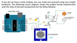
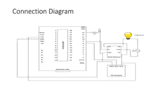
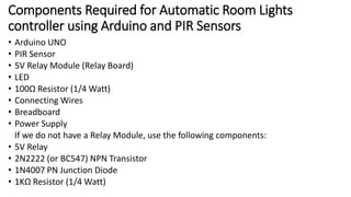
The document discusses an automatic room lights controller project utilizing Arduino and a PIR sensor, designed to activate lights based on human motion detection. Key components include the Arduino, PIR sensor, and relay module, with detailed circuit designs, working mechanisms, and applications provided. Potential applications of this system extend to garage lights, bathroom lights, hand dryers, and security lights.


![Human presence detection based room light controller using pir2.pptx [repaired]](https://cdn.slidesharecdn.com/ss_thumbnails/humanpresencedetectionbasedroomlightcontrollerusingpir2-160418083434-thumbnail.jpg?width=640&height=640&fit=bounds)


