Download to read offline

![Automatic Lighting Controller
34
The names of 6 group members CELUS, DELLA, DINA, ELIENA, FARZEEN, FATHIMA.
This is displayed repeatedly until interrupt is given. (Interrupt here is the light intensity).
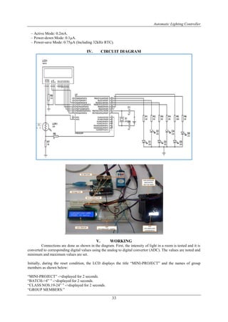
The value of light intensity is read by the Light Detecting Resistor (LDR) and gives out corresponding
voltage value, which is fed to analog port (A0) of arduino platform. The value is then processed and then
converted to percentage (minimum set value corresponds to 0% and maximum set value corresponds to 100%).
The number of LED to be lit is pre-programmed and is set as follows:
If LUMINANCE = 100 %, number of LEDs to be lit = 0.
If LUMINANCE < 90%, number of LEDs to be lit = 1.
If LUMINANCE < 70%, number of LEDs to be lit = 2.
If LUMINANCE < 50%, number of LEDs to be lit = 3.
If LUMINANCE < 30%, number of LEDs to be lit = 4.
If LUMINANCE < 10%, number of LEDs to be lit = 5.
If LUMINANCE = 0%, number of LEDs to be lit = 6.
The energy consumed is also monitored by counting the number of bulbs lit. Wattage of the bulbs connected can
be pre set.
lcd.print(lum*10); //Here the wattage per lamp is set to 10W.
In this way, the necessary number of bulbs to be lit in a room is controlled by the light intensity in the room.
Hence, energy conservation can be effectively carried out in this present scenario of energy crisis.
VI. PROGRAM CODE
#include<LiquidCrystal.h> //Header file for including lcd functions.
LiquidCrystal lcd(7,6,5,4,3,2); //Assigning ports to connect lcd.
int minlum=150; //Setting up lumination limits.
int maxlum=950; //Setting up lumination limits.
/*Function for setting up I/O ports, start up display etc...*/
void setup()
{
int l,n;
char name[]={' ',' ',' ',' ',' ',' ',' ',' ',' ',' ',' ',' ',' ',' ',' ',' ','C','E','L','U','S',',',' ','D','E','L','L','A',',',' ','D','I','N','A',',','
','E','L','I','E','N','A',',',' ','F','A','R','Z','E','E','N',',',' ','F','A','T','H','I','M','A','.','.','.',' ',' ',' ',' ',' ',' ',' ',' ',' ',' ',' ',' ',' ',' ',' ','
'};
for(int j=8;j<14;j++)
pinMode(j,OUTPUT); //Setting pins 8 to 13 as outputs.
lcd.begin(16,2); //Initializing lcd display.
Serial.begin(9600);
//Setting baud rate for serial communication.
/*Loop for initial display*/
do
{](https://image.slidesharecdn.com/e1022936-140322033727-phpapp01/85/International-Journal-of-Engineering-Research-and-Development-6-320.jpg)
![Automatic Lighting Controller
35
lcd.clear();
lcd.print(" MINI-PROJECT "); //Print to lcd screen.
delay(2000); //Delay for 2sec.
lcd.setCursor(0,1);
lcd.print(" BATCH->4 ");
delay(2000);
lcd.setCursor(0,1);
lcd.print("CLASS NOS: 19-24");
delay(2000);
lcd.clear();
lcd.print("GROUP MEMBERS:");
lcd.setCursor(0,1);
n=0;
do
{
lcd.setCursor(0,1);
for(int i=n;i<n+17;i++)
lcd.print(name[i]);
delay(250);
n++;
l=analogRead(A0);
}while(n<64&&l<500); //Continue display loop untill interrupt.
}while(l<500); //Continue display loop untill interrupt.
}
/*Execution function, main function for continuous executuion.*/
void loop()
{
int lum=analogRead(A0); //Read the analog value.
lum=constrain(lum,minlum,maxlum); //Constrain the value to avoid noise.
int lumper=map(lum,minlum,maxlum,0,100); //Convert the analog to percentage.
Serial.print("Value = "); //Send value to computer.
Serial.println(lum);
lum=(10-(lumper/10))/2; //Calculating the number of lamps to be lit.
/*printing the values to LCD*/
lcd.clear();
lcd.print("LUMINATION:");
lcd.print(lumper);
lcd.print("%");
/*Controling the lamps*/
for(int i=0;i<6;i++)
{
if(i<lum)
{
digitalWrite(i+8,HIGH); //Turn lamps ON
}
else
{
digitalWrite(i+8,LOW); //Turn lamps OFF
}
/*Turning all lamps ON when 0 light intensity*/
if(lumper==0)
for(int k=8;k<14;k++)
digitalWrite(k,HIGH);
}
if(lumper==0)
lum=6;
/*Display to LCD*/](https://image.slidesharecdn.com/e1022936-140322033727-phpapp01/85/International-Journal-of-Engineering-Research-and-Development-7-320.jpg)

The document presents a project on an Automatic Lighting Controller aimed at energy conservation by regulating lighting based on room luminosity. Utilizing an Arduino microcontroller, LDR sensors, and an LCD display, the system automatically adjusts the number of lights based on the detected light intensity, thus minimizing unnecessary energy consumption. The project outlines the methodology, components used, and potential applications in various settings such as homes, schools, and offices.