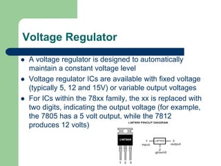
Presentation on
Automatic Light
control at Night
College of Engineering Science
& Technology, Lucknow
Submitted To:-
Electrical & Electronics
Department
Submitted By:-
Shubhan Raj
Karan Pratap Singh
Deepshikha Tiwari
Shikha Sharma
Abstract:-
 Automatic light needs no manual operation for
switching ON and OFF when there is need of light.
 In fact we can use this circuit to implement any type
of automatic night light.
Contents
 Introduction
 Hardware Requirement
 Block Diagram
 Circuit Diagram
 Hardware Discription
 Simulation
 PCB Layout
 Advantage
 Conclusion
Introduction
 Automatic light needs no manual operation for switching
ON and OFF when there is need of light.
 It detects itself whether there is need for light or not. When
darkness rises to a certain value then automatically light is
switched ON and when there is other source of light i.e.
day time, the light gets OFF.
 The sensitive of the light can be adjusted. The circuit thus
saves the electrical power as well as man power.
 The principle involves the detection of the intensity of light
with help of LDR which changes the value of resistance
across it on the basis of light.
Block diagram:
Circuit Diagram:
Components:
 LDR
 IC ULN2803 (Relay Driver)
 IC LM 324
 LM7805 (Voltage Regulator)
 Resistor
 Variable Resistor
 Capacitor
 Relay
 LED
 Bulb
 Connection wire
 Soldering Tools
LDR
 The light dependant resistor is an electronic component
whose resistance decreases with increasing light
intensity. It is also called as “Photo Resistor” or “Photo
conductor”
 The light dependant resistor uses high resistance
semiconductor material. (Cadmium Sulphide).When light
falls on such a semiconductor the bound electrons [i.e.
Valence electrons] get the light energy from the incident
photos
Description of Hardware :
LED
 A light-emitting diode (LED) is a semiconductor light
source. LEDs are used as indicator lamps in many
devices and are increasingly used for other lighting
 Appearing as practical electronic components early
LEDs emitted low-intensity red light, but modern
versions are available across the visible, ultraviolet,
and infrared wavelengths, with very high brightness.
 It is a passive component having two terminals that
are used to manage the current flow in the circuit.
 A current that flows via a resistor is directly
proportional to the voltage that appeared into
resistor.
 Two types:
(1) Fixed value resistor
(2) Variable resistor
Resistor:
Relay Driver
 The eight NPN Darlington connected transistors in this family of
arrays are ideally suited for interfacing between low logic level
digital circuitry (such as TTL, CMOS or PMOS/NMOS) and the
higher current/voltage requirements of lamps, relays, printer
hammers or other similar loads.
 The major advantage of using this IC is that it can fulfill the
need for high voltage and high current also. This is enabled
through a low voltage and low current source to give high
voltage and high current output.
LM324
 LM324 is a 14pin IC consisting of four independent
operational amplifiers compensated in a single
package.
 Op-amps are high gain electronic voltage amplifier
with differential input and, usually, a single-ended
output. The output voltage is many times higher than
the voltage difference between input terminals of an
op-amp.
Voltage Regulator
 A voltage regulator is designed to automatically
maintain a constant voltage level
 Voltage regulator ICs are available with fixed voltage
(typically 5, 12 and 15V) or variable output voltages
 For ICs within the 78xx family, the xx is replaced with
two digits, indicating the output voltage (for example,
the 7805 has a 5 volt output, while the 7812
produces 12 volts)
Relay
 Relays are electromechanical switches.
 Relays have two circuits: A control circuit (shown in
GREEN) and a load circuit (shown in RED).
 The control circuit has small control coil while the
load circuit has a switch. The coil controls the
operation of the switch.
Capacitor
 To store electricity, or electrical energy.
 Also functions as filter, passing AC, and blocking
DC.
 Apply DC voltage- electric charge is stored on each
electrode.
 Three types of capacitor i.e. ceramic capacitor &
electrolytic capacitor and variable.
 Variable capacitors.
Simulation (using Proteus):
PCB Layout
Advantages:
 No man power required.
 Less Consumption of electrical energy.
 Less maintenance.
 Cheap and economical.
Disadvantage:-
In Sunny and rainy days, on and off time differ
notice.
Conclusion:
 In coming days, this will prove a great boon
to the world, since it will save a lot of
electricity of power plants that gets wasted in
illuminating the street lights. As the
conventional sources are depleting very fast,
then it`s time to think of alternatives.
Future Scope:-
 We can implement this project for street
lamp and also for night lamp of the room.
automatic light control at night ppt by Shubhan raj

automatic light control at night ppt by Shubhan raj

  • 1.
    Presentation on Automatic Light controlat Night College of Engineering Science & Technology, Lucknow Submitted To:- Electrical & Electronics Department Submitted By:- Shubhan Raj Karan Pratap Singh Deepshikha Tiwari Shikha Sharma
  • 2.
    Abstract:-  Automatic lightneeds no manual operation for switching ON and OFF when there is need of light.  In fact we can use this circuit to implement any type of automatic night light.
  • 3.
    Contents  Introduction  HardwareRequirement  Block Diagram  Circuit Diagram  Hardware Discription  Simulation  PCB Layout  Advantage  Conclusion
  • 4.
    Introduction  Automatic lightneeds no manual operation for switching ON and OFF when there is need of light.  It detects itself whether there is need for light or not. When darkness rises to a certain value then automatically light is switched ON and when there is other source of light i.e. day time, the light gets OFF.  The sensitive of the light can be adjusted. The circuit thus saves the electrical power as well as man power.  The principle involves the detection of the intensity of light with help of LDR which changes the value of resistance across it on the basis of light.
  • 5.
  • 6.
  • 7.
    Components:  LDR  ICULN2803 (Relay Driver)  IC LM 324  LM7805 (Voltage Regulator)  Resistor  Variable Resistor  Capacitor  Relay  LED  Bulb  Connection wire  Soldering Tools
  • 8.
    LDR  The lightdependant resistor is an electronic component whose resistance decreases with increasing light intensity. It is also called as “Photo Resistor” or “Photo conductor”  The light dependant resistor uses high resistance semiconductor material. (Cadmium Sulphide).When light falls on such a semiconductor the bound electrons [i.e. Valence electrons] get the light energy from the incident photos Description of Hardware :
  • 9.
    LED  A light-emittingdiode (LED) is a semiconductor light source. LEDs are used as indicator lamps in many devices and are increasingly used for other lighting  Appearing as practical electronic components early LEDs emitted low-intensity red light, but modern versions are available across the visible, ultraviolet, and infrared wavelengths, with very high brightness.
  • 10.
     It isa passive component having two terminals that are used to manage the current flow in the circuit.  A current that flows via a resistor is directly proportional to the voltage that appeared into resistor.  Two types: (1) Fixed value resistor (2) Variable resistor Resistor:
  • 11.
    Relay Driver  Theeight NPN Darlington connected transistors in this family of arrays are ideally suited for interfacing between low logic level digital circuitry (such as TTL, CMOS or PMOS/NMOS) and the higher current/voltage requirements of lamps, relays, printer hammers or other similar loads.  The major advantage of using this IC is that it can fulfill the need for high voltage and high current also. This is enabled through a low voltage and low current source to give high voltage and high current output.
  • 12.
    LM324  LM324 isa 14pin IC consisting of four independent operational amplifiers compensated in a single package.  Op-amps are high gain electronic voltage amplifier with differential input and, usually, a single-ended output. The output voltage is many times higher than the voltage difference between input terminals of an op-amp.
  • 13.
    Voltage Regulator  Avoltage regulator is designed to automatically maintain a constant voltage level  Voltage regulator ICs are available with fixed voltage (typically 5, 12 and 15V) or variable output voltages  For ICs within the 78xx family, the xx is replaced with two digits, indicating the output voltage (for example, the 7805 has a 5 volt output, while the 7812 produces 12 volts)
  • 14.
    Relay  Relays areelectromechanical switches.  Relays have two circuits: A control circuit (shown in GREEN) and a load circuit (shown in RED).  The control circuit has small control coil while the load circuit has a switch. The coil controls the operation of the switch.
  • 15.
    Capacitor  To storeelectricity, or electrical energy.  Also functions as filter, passing AC, and blocking DC.  Apply DC voltage- electric charge is stored on each electrode.  Three types of capacitor i.e. ceramic capacitor & electrolytic capacitor and variable.  Variable capacitors.
  • 16.
  • 17.
  • 18.
    Advantages:  No manpower required.  Less Consumption of electrical energy.  Less maintenance.  Cheap and economical. Disadvantage:- In Sunny and rainy days, on and off time differ notice.
  • 19.
    Conclusion:  In comingdays, this will prove a great boon to the world, since it will save a lot of electricity of power plants that gets wasted in illuminating the street lights. As the conventional sources are depleting very fast, then it`s time to think of alternatives.
  • 20.
    Future Scope:-  Wecan implement this project for street lamp and also for night lamp of the room.