Download to read offline

![International Research Journal of Engineering and Technology (IRJET) e-ISSN: 2395-0056
Volume: 09 Issue: 05 | May 2022 www.irjet.net p-ISSN: 2395-0072
© 2022, IRJET | Impact Factor value: 7.529 | ISO 9001:2008 Certified Journal | Page 1045
REFERENCES
[1]. TinkercadArduino Tutorials:Tutorials:AutomaticRoom
Lightning System
[2].http://education.rec.ri.cmu.edu/content/electronics/boe
/ir _sensor/1.html
[3] Automatic Room Light Controller with bidirectional
visitor counter | VOL-I Issue-4| ISSN: 2395-4841
.http://www.ijictrd.net/papers/IJICTRDV1I4005.pdf
[4].http://www.digchip.com/datasheets/parts/datasheet/1
05/ CL100-pdf.php
[5].http://www.datasheetarchive.com/dlmain/Datasheets3
12/174867.pdf
[6].https://www.fairchildsemi.com/datasheets/LM/LM7805
. pdf
[7] www.ijictrd.net
[8] www.slideshare.net
[9] lib.chipresistor.ru
BIOGRAPHIES
Mir Amjad Ali is a B.Tech Student,
Department of Electronics and
Computer Engineering, Sreenidhi
Institute of Science & Technology,
Hyderabad.
Mail id: rehan1136ali@gmail.com
Mohammad Abdul Nabeel Hasnain
is a B.E Student, Department of
Electrical and Instrumentation
Engineering, Muffakham Jah
College of Engineering and
Technology, Hyderabad.
Mail id: hasnainabeel@gmail.com](https://image.slidesharecdn.com/irjet-v9i5270-220930110051-fab449c8/85/Automatic-Room-Lighting-System-4-320.jpg)

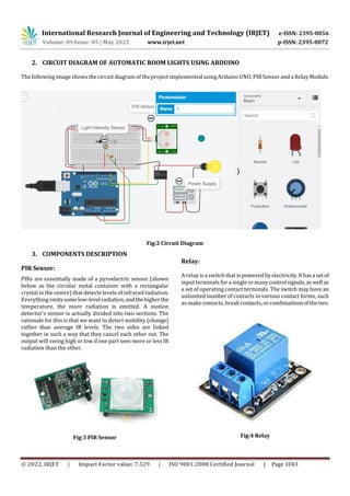
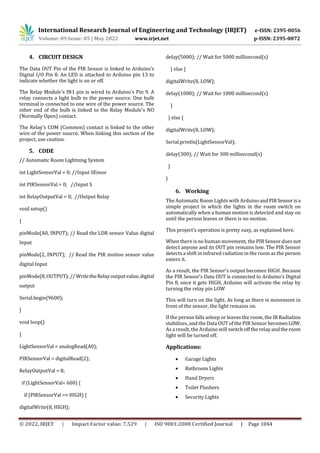
This document describes an automatic room lighting system that uses an Arduino, PIR sensor, and relay module. The system turns lights on when motion is detected by the PIR sensor and turns them off after a period of inactivity. It provides energy savings by not requiring lights to be manually switched on and off. When motion is detected, the PIR sensor output becomes high, triggering the Arduino to activate the relay and turn on the lights. The lights remain on as long as movement continues. Without motion, the PIR output becomes low and the Arduino turns off the relay and lights. Applications include garage, bathroom, and security lighting.


![Human presence detection based room light controller using pir2.pptx [repaired]](https://cdn.slidesharecdn.com/ss_thumbnails/humanpresencedetectionbasedroomlightcontrollerusingpir2-160418083434-thumbnail.jpg?width=640&height=640&fit=bounds)


