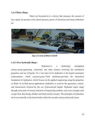
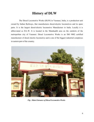
SUMMER TRAINING REPORT
MAINTENCE SER
CENTRAL TRANSPORT SHOP
Submitted in partial fulfillment of the
Requirement for the award of the
BACHELOR OF TECHNOLOGY
AKASH
UMANATH SINGH INSTITUTE OF ENGINEERING & TECHNOLOGY
VEER BAHADUR SINGH PURVANCHAL UNIVERSITY
JAUNPUR, UTTAR PRADESH
SUMMER TRAINING REPORT
ON
MAINTENCE SERVICE SHOP, SCADA
CENTRAL TRANSPORT SHOP and COLONY
Submitted in partial fulfillment of the
Requirement for the award of the
Degree of
BACHELOR OF TECHNOLOGY
IN
(Electrical Engineering)
BY
AKASH VISHWAKARMA
(215507)
Under the guidance of
MR. ROHIT RASTOGI
NSTITUTE OF ENGINEERING & TECHNOLOGY
VEER BAHADUR SINGH PURVANCHAL UNIVERSITY
JAUNPUR, UTTAR PRADESH
SUMMER TRAINING REPORT
and COLONY
NSTITUTE OF ENGINEERING & TECHNOLOGY
VEER BAHADUR SINGH PURVANCHAL UNIVERSITY
2
CERTIFICATE
This is to certify that AKASH VISHWAKARMA Roll no. 215507 has
completed objective formulation of training titled, “MAINTENCE SERVICE
SHOP , CENTRAL TRANSPORT SHOP, SCADA and COLONY ” under my
guidance and supervision. To the best of my knowledge, the present work is the
result of her original investigation and study. No part of the summer training is has
ever been submitted for any other degree at any University.
The industrial training
is fit for submission and the partial fulfillment of the conditions for the award of
Bachelor of Technology.
Date:- (RAJNEESH BHASKAR)
Head of Department of Electrical Engineering
Designation
U.N.S. Institute of Technology
V.B.S. Purvanchal University
Jaunpur, (U.P.)
3
DECLARATION
Myself Akash Vishwakarma , Roll No- 215507, student of B.Tech.
(Electrical Engineering) 4th year of Umanath Singh Institute of Engineering and
Technology, Veer Bahadur Singh Purvanchal University, Jaunpur hereby declare
that my training report on “ DIESEL LOCOMOTIVE WORKS ” is an original
and authenticated word done by me and the best of my knowledge and belief. I
further declare that it has not been submitted elsewhere by any person in any of the
institutes for the degree of bachelor’s of Technology.
Signature
Name : Akash Vishwakarma
Branch : E.E. (4th year)
Roll No : 215507
4
ACKNOWLEDGEMENT
Summer training has an important role in exposing the real life situation in
an industry. It was a great experience for me to work on training at DIESEL
LOCOMOTIVE WORKSHOP through which I could learn to work in a
professional environment. I would like to thank the people who guided me and
have been a constant source of inspiration throughout the tenure of my summer
training. I express my sincere thanks and regards to the principle of technical
training center, DLW for giving me the opportunity of training in Diesel
Locomotive Works, Varanasi.
I also wish my deep sense of gratitude to Dr.
Rajneesh Bhaskar (HOD: Electrical Engineering). All the faculty members of EE
department of U.N.S. Institute of Technology whose guidance and
encouragement made my training successful.
Signature
Name : Akash Vishwakarma
Branch : E.E. (4th year)
Roll No : 215507
5
ABSTRACT
The industrial training report of DLW (DIESEL LOCOMOTIVE
WORKS) is various trade. i.e. Electronics and communication , Electrical,
Mechanical, Electrical & Electronics and many Diploma holders are participated
.The content of my industrial topic MAINTENCE SERVICE SHOP , CENTRAL
TRANSPORT SHOP, SCADA and COLONY. In Maintenance Service Shop, we
are discus about how to remove defect from the circuit board and any part of
system. The second is CTS (Central Transport Shop), I learn about transportation
of Light and Heavy equipments and maintenance of transport vehicle. After
completed the Central Transport Shop going to discus about SCADA. Than the last
of my section is Colony, in this shop I learn to explain the system of colony line
distribution and how to generate high power electricity. This report is written on
the basis of practical knowledge of acquired by me during the period of practical
training taken at, Diesel Locomotive Works Varanasi. This report is presented in
very simple & understanding language and it is comprise of four sections namely
MAINTENCE SERVICE SHOP , CENTRAL TRANSPORT SHOP, SCADA and
COLONY areas.
6
TABLE OF CONTENTS
CONTENT PAGE NO.
Acknowledgement……………………………………………………………… 4
Abstract……………………………………………………………………………5
Table of Contents…………………………………………………………………6
List of Figures…………………………………………………………………… 7
HISTORY OF DLW 8-9
CHAPTER 1: Maintenance Service Shop 10-14
Introduction to MSS
1.1Classification of MSS
1.1.1 Winding Shop
1.1.2 Electronic Shop
1.1.3 Meter Shop
1.1.4 Battery Shop
1.1.5 Over Hydraulic Shop
CHAPTER 2: Central Transport Shop 15-19
Introduction to CTS
2.1 Material Handling Equipments
1. Transport equipment
2. Positioning equipment
3. Unit load formation equipment
4. Storage equipment
CHAPTER 3: SCADA 20-22
Introduction to SCADA
3.1 Components of SCADA system
1. Supervisory computers
2. Remote terminal units
3. Programmable logic controllers
4. Communication infrastructure
5. Human-machine interface
CHAPTER 4: Colony 23-26
Introduction to Colony
Generation
Primary and Secondary transmission
Primary and secondary distribution
Elements of Sub-station
Conclusion………………………………………………………………………………27
7
LIST OF FIGURE
Name of Fig. ……………………………………………………………Page No.
Fig.1 Main Entrance of DLW 8
Fig.2 A view of TTC 9
Fig.1.1 A view of MSS 10
Fig.1.2 Internal Architecture of 3-phase motor 11
Fig.1.3 A view of electronics lab in DLW 12
Fig.1.4 Internal Architecture of Battery 13
Fig.1.5 A view of meter in DLW 14
Fig.2.1 A view of conveyer 16
Fig.2.2 A view of Fork Lift Truck 17
Fig.2.3 A view of Crane 18
Fig.2.4 A view of CTS 18
Fig.3.1 A view of SCADA 20
Fig.4.1 A view of Supply system 23
Fig.4.2 A view of 132KV Sub-station in DLW 25
8
History of DLW
The Diesel Locomotive Works (DLW) in Varanasi, India, is a production unit
owned by Indian Railways, that manufactures diesel-electric locomotives and its spare
parts. It is the largest diesel-electric locomotive Manufacture in India. Locally it is
abbreviated as D.L.W. It is located in the Manduadih area on the outskirts of the
metropolitan city of Varanasi. Diesel Locomotive Works is an ISO 9002 certified
manufacturer of diesel electric locomotive and is one of the biggest industrial complexes
in eastern part of the country.
Fig : Main Entrance of Diesel Locomotive Works
Diesel Locomotive
from M/s. ALCO/USA with a modest
DLW is the largest Diesel Locomotive manufacturer
In order to capture export market & widen its
in to a contract for Transfer of Technology (TOT) with
manufacture of 4000 HP state of the art locos at DLW. After
technology, DLW will become the only factory in the world capable of
as well as General Motors designs of locomotives.Dlw is only manufacture of diesel
electric locomotive with both ALCOand GENERAL MOTORSTechnologies in the
world.DLW exports locos to SRILANKA , MALAYSIA, BANGLADESH, TANZANIA,
VIETANNAM.
Fig : A view of Technical Training Center
Diesel Locomotive Works was set up in 1961 with technical collaboration
from M/s. ALCO/USA with a modest beginning of manufacturing 4 locos 1964, today
Diesel Locomotive manufacturer in the world, and the largest in Asia.
In order to capture export market & widen its product range.
Indian railway en
in to a contract for Transfer of Technology (TOT) with M/s. General Motors, USA for
manufacture of 4000 HP state of the art locos at DLW. After assimilation of this
technology, DLW will become the only factory in the world capable of producing ALCO
s well as General Motors designs of locomotives.Dlw is only manufacture of diesel
electric locomotive with both ALCOand GENERAL MOTORSTechnologies in the
world.DLW exports locos to SRILANKA , MALAYSIA, BANGLADESH, TANZANIA,
Fig : A view of Technical Training Center
9
Works was set up in 1961 with technical collaboration
beginning of manufacturing 4 locos 1964, today
in the world, and the largest in Asia.
Indian railway entered
M/s. General Motors, USA for
assimilation of this
producing ALCO
s well as General Motors designs of locomotives.Dlw is only manufacture of diesel –
electric locomotive with both ALCOand GENERAL MOTORSTechnologies in the
world.DLW exports locos to SRILANKA , MALAYSIA, BANGLADESH, TANZANIA,
1. Maintenance Service Shop
Introduction:-
Maintenance, repair, and overhaul involve fixing any sort of
mechanical, plumbing or electrical device should it become out of order or broken
(known as repair, unscheduled, or casualty maintenance). It also includes performing
routine actions which keep t
maintenance) or prevent trouble from arising (preventive maintenance). MRO may be
defined as, "All actions which have the objective of retaining or restoring an item in or to
a state in which it can perform it
of all technical and corresponding administrative, managerial, and supervision actions.
Fig 1.1 A view of Maintenance Service Shop in DLW
This has come to often include both
effective practices to keep equipment ready for operation at the
a system lifecycle.
Maintenance Service Shop
Maintenance, repair, and overhaul involve fixing any sort of
mechanical, plumbing or electrical device should it become out of order or broken
(known as repair, unscheduled, or casualty maintenance). It also includes performing
routine actions which keep the device in working order (known as scheduled
maintenance) or prevent trouble from arising (preventive maintenance). MRO may be
defined as, "All actions which have the objective of retaining or restoring an item in or to
a state in which it can perform its required function. The actions include the combination
of all technical and corresponding administrative, managerial, and supervision actions.
Fig 1.1 A view of Maintenance Service Shop in DLW
This has come to often include both scheduled and preventive maintenance as cost
effective practices to keep equipment ready for operation at the utilization
10
Maintenance Service Shop
Maintenance, repair, and overhaul involve fixing any sort of
mechanical, plumbing or electrical device should it become out of order or broken
(known as repair, unscheduled, or casualty maintenance). It also includes performing
he device in working order (known as scheduled
maintenance) or prevent trouble from arising (preventive maintenance). MRO may be
defined as, "All actions which have the objective of retaining or restoring an item in or to
s required function. The actions include the combination
of all technical and corresponding administrative, managerial, and supervision actions.
maintenance as cost-
utilization stage of
11
1.1 Classification of MSS:-
There are main five types of maintains service shop,
these are following below-
1. Winding Shop
2. Electronics Lab
3. Battery Shop
4. Meter Shop
5. Over Hydraulic Shop
1.1.1 Winding Shop:-
An ideal step motor would have zero mechanical friction,
its torque would be proportional to ampere-turns and its only electrical characteristic
would be inductance. Ampere-turns simply mean that torque is proportional to the
number of turns of wire in the motor’s stator multiplied by the current passing through
those turns of wire. Anytime there are turns of wire surrounding a magnetic material such
as the iron in the motor’s stator, it will have an electrical property called inductance.
Inductance describes the energy stored in a magnetic field anytime current passes through
this coil of wire.
Fig.1.2 Internal part of 3-phase motor
12
1.1.2 Electronic Lab:-
There is a full-fledged Electronic Lab to cater to maintenance
need of highly sophisticated CNC machines and component / subassembly level trouble
shooting of PCBs, Servo Drives, and Microprocessor based controllers and electronic
units. This Lab also supports other Zonal Railways in repair of PCBs.
Fig 1.3 A view of Electronic lab in DLW
Another major role where this section is involved is in infrastructure development and
maintenance activities. This section is responsible for installation and maintenance of
facilities vital for effective functioning of the organization like strong communication
setup, electric substation, centralized UPS and other useful appliances
13
1.1.3 Battery Shop:-
An electric battery is a device consisting of two or more
electrochemical cells that convert stored chemical energy into electrical energy. Each cell
has a positive terminal, or cathode, and a negative terminal, or anode. The terminal
marked positive is at a higher electrical potential energy than is the terminal marked
negative. When a battery is connected to an external circuit , Electrolytes are able to
move as ions within, allowing the chemical reactions to be completed at the separate
terminals and so deliver energy to the external circuit. It is the movement of those ions
within the battery which allows current to flow out of the battery to perform work.
Chemical action during discharge
Pbo2 + H2 + H2SO4= PBSO4 + 2H2O ( at + Ve )------ (i)
Pb + SO4 = PbSO4 (at – Ve ) --------------- (ii)
Chemical action during charging
PbSO4 + H2 = Pb + H2SO4(at – Ve )------------- (iii)
PbSO4 + SO4 + 2H2O = PbO2 +2H2O ( at + Ve )------- (iv)
Fig 1.3 Internal Architecture of Battery
14
1.1.4 Meter Shop:-
Meter (in locomotive) is a device that measures the amount of
loco speed, air pressure ,Fuel, diesel pressure, power of electricity and meter-calibration
etc.
Fig 1.5 A view of Meter in DLW
1.1.5 Over hydraulic Shop:-
Hydraulics is a technology and applied
science using engineering , chemistry, and other sciences involving the mechanical
properties and use of liquids. At a very basic level, hydraulics is the liquid counterpart
of pneumatics, which concerns gases. Fluid mechanics provides the theoretical
foundation for hydraulics, which focuses on the applied engineering using the properties
of fluids. In its fluid power applications, hydraulics is used for the generation, control,
and transmission of power by the use of pressurized liquids. Hydraulic topics range
through some parts of science and most of engineering modules, and cover concepts such
as pipe flow dam design, fluidics and fluid control circuitry. The principles of hydraulics
are in use naturally in the human body within the vascular system and erectile tissue
15
2. Central Transport Shop
Introduction:-
Meaning of the transport is movement of any things. But in
workshops, it can be defined as movement of machines or materials from one place to
another place for utilization called transport. The vehicle by which these are transported
called transportation. In workshops Fort Lift Truck are used for transport. In the
workshop we also use Mini Crane or Crane for movement of light and heavy part of
machine.
On the process of working if the any part of transportation vehicle getting
damage, such as motor does not working properly . After several testing resolve the
problem which occurs in motor. In central transport shop electrical department works is
maintenance of motor. If the motor getting damage and not to be operate again then it can
be replaced by new motor. The efficiency of new motor is better than previous motor.
2.1 Material handling equipment:-
Material handling equipment is
mechanical equipment used for the movement, storage, control and protection of
materials, goods and products throughout the process of manufacturing, distribution,
consumption and disposal.
The different types of handling equipment can be classified
into four major categories-
1. Transport equipment
2. Positioning equipment
3. Unit load formation equipment
4. Storage equipment
16
1.Transport equipment:-
Transport equipment is used to move material from one
location to another (e.g., between workplaces, between a loading dock and a storage area,
etc.) within a facility or at a site. The major subcategories of transport equipment are:
Conveyors. Equipment used to move materials over a fixed path between specific points.
There are some examples of transport equipments-
(i). Conveyors:- Conveyors are used when material is to be moved frequently
between specific points over a fixed path and when there is a sufficient flow volume to
justify the fixed conveyor investment.
Fig 2.1: A view of conveyor
(ii). Fork Lift Truck:- A forklift (also called lift truck, jitney, fork truck, fork hoist,
and forklift truck) is a powered industrial truck used to lift and move materials over short
distances. The forklift was developed in the early 20th century by various companies,
including Clark. Industrial trucks are trucks that are not licensed to travel on public roads
(commercial trucks are licensed to travel on public roads). Industrial trucks are used to
move materials over variable paths and when there is insufficient (or intermittent) flow
volume such that the use of a conveyor cannot be justified.
Forklifts are rated for loads at a specified maximum weight and a specified forward
center of gravity. It can be lifted the load upto 5
Fig2.2 A View of Fork Lift Truck
(iii). Crane:- Cranes are used to transport loads over variable (horizontal and vertical)
paths within a restricted area and when there is insufficient (or intermittent) flow volume
such that the use of a conveyor cannot be justified. Cranes provide more flexibility in
movement than conveyors because the loads handled can be more varied with respect to
their shape and weight. Cranes provide less flexibility in movement than industrial trucks
because they only can operate within a restricted area, though some can operate on a
portable base. Most cranes utilize trolley
for vertical movement. In crane, maintenance of moving parts are include in electrical
department.
Forklifts are rated for loads at a specified maximum weight and a specified forward
center of gravity. It can be lifted the load upto 5000 pound safely.
Fig2.2 A View of Fork Lift Truck
are used to transport loads over variable (horizontal and vertical)
paths within a restricted area and when there is insufficient (or intermittent) flow volume
use of a conveyor cannot be justified. Cranes provide more flexibility in
movement than conveyors because the loads handled can be more varied with respect to
their shape and weight. Cranes provide less flexibility in movement than industrial trucks
e they only can operate within a restricted area, though some can operate on a
portable base. Most cranes utilize trolley-and-tracks for horizontal movement and hoists
In crane, maintenance of moving parts are include in electrical
17
Forklifts are rated for loads at a specified maximum weight and a specified forward
are used to transport loads over variable (horizontal and vertical)
paths within a restricted area and when there is insufficient (or intermittent) flow volume
use of a conveyor cannot be justified. Cranes provide more flexibility in
movement than conveyors because the loads handled can be more varied with respect to
their shape and weight. Cranes provide less flexibility in movement than industrial trucks
e they only can operate within a restricted area, though some can operate on a
tracks for horizontal movement and hoists
In crane, maintenance of moving parts are include in electrical
Fig 2.3
All above equipments such as : conveyers, Fort lift truck or industrial truck and crane are
used for transport. If these transport equipments are getting damage then it repair
central transport shop.
Fig 2.4 A view of Central Transport shop
Fig 2.3: A view of Crane
All above equipments such as : conveyers, Fort lift truck or industrial truck and crane are
used for transport. If these transport equipments are getting damage then it repair
Fig 2.4 A view of Central Transport shop
18
All above equipments such as : conveyers, Fort lift truck or industrial truck and crane are
used for transport. If these transport equipments are getting damage then it repair in the
19
2.Positioning equipment:-
Positioning equipment is used to handle material at a
single location. It can be used at a workplace to feed, orient, load/unload, or otherwise
manipulate materials so that are in the correct position for subsequent handling,
machining, transport, or storage. Examples of positioning equipment include lift/tilt/turn
tables, hoists, balancers, manipulators, and industrial robots.
3. Unit load formation equipment:-
Unit load formation equipment is used to
restrict materials so that they maintain their integrity when handled a single load during
transport and for storage. If materials are self-restraining (e.g., a single part or
interlocking parts), then they can be formed into a unit load with no equipment. Examples
of unit load formation equipment include pallets, skids, slipsheets, tote pans, bins/baskets,
cartons, bags, and crates.
4.Storage equipment:-
Storage equipment is used for holding or buffering materials
over a period of time. The design of each type of storage equipment, along with its use
in warehouse design, represents a trade-off between minimizing handling costs, by
making material easily accessible, and maximizing the utilization of space. If materials
are stacked directly on the floor, then no storage equipment is required, but, on average,
each different item in storage will have a stack only half full; to increase cube utilization,
storage racks can be used to allow multiple stacks of different items to occupy the same
floor space at different levels.
Introduction:-
Supervisory control and data acquisition
system architecture that uses computers, networked data communications and
user interfaces for high-level process supervisory management, but uses other peripheral
devices such as programmable logic controller (PLC) and discrete
interface with the process plant or machinery. The operator interfaces that enable
monitoring and the issuing of process commands, such as controller set point changes,
are handled through the SCADA computer system.
to become very similar to distributed control systems
means of interfacing with the plant. They can control large
include multiple sites, and work over large distances as we
3.SCADA
Supervisory control and data acquisition (SCADA) is a
system architecture that uses computers, networked data communications and
level process supervisory management, but uses other peripheral
rammable logic controller (PLC) and discrete PID controllers
interface with the process plant or machinery. The operator interfaces that enable
monitoring and the issuing of process commands, such as controller set point changes,
SCADA computer system.
large SCADA systems have grown
distributed control systems in function, but using multiple
means of interfacing with the plant. They can control large-scale processes that can
include multiple sites, and work over large distances as well as small distance.
Fig 3.1: A view of SCADA
20
(SCADA) is a control
system architecture that uses computers, networked data communications and graphical
level process supervisory management, but uses other peripheral
PID controllers to
interface with the process plant or machinery. The operator interfaces that enable
monitoring and the issuing of process commands, such as controller set point changes,
SCADA systems have grown
in function, but using multiple
scale processes that can
ll as small distance.
21
However, the real-time control logic or controller calculations are performed by
networked modules that connect to the field sensors and actuators.
3.1 Component of SCADA system:-
There are following components of SCADA
system-
1. Supervisory computers
2. Remote terminal units
3. Programmable logic controllers
4. Communication infrastructure
5. Human-machine interface
1.Supervisory computers:-
In smaller SCADA systems, the supervisory computer
may be composed of a single PC, in which case the HMI is a part of this computer. In
larger SCADA systems, the master station may include several HMIs hosted on client
computers, multiple servers for data acquisition, distributed software applications, and
disaster recovery sites. To increase the integrity of the system the multiple servers will
often be configured in a dual-redundant or hot-standby formation providing continuous
control and monitoring in the event of a server malfunction or breakdown.
2.Remote terminal units:-
Remote terminal units, also known as (RTUs), connect to
sensors and actuators in the process, and are networked to the supervisory computer
system. RTUs are "intelligent I/O" and often have embedded control capabilities such
as ladder logic in order to accomplish boolean logic operations.
22
3.Programmable logic controllers:-
A programmable logic controller (PLC)
or programmable controller is an industrial digital computer which has
been ruggedized and adapted for the control of manufacturing processes, such
as assembly lines, or robotic devices, or any activity that requires high reliability control
and ease of programming and process fault diagnosis.
These are connected to sensors
and actuators in the process, and are networked to the supervisory system in the same
way as RTUs. PLCs have more sophisticated embedded control capabilities than RTUs,
and are programmed in one or more IEC 61131-3 programming languages. PLCs are
often used in place of RTUs as field devices because they are more economical, versatile,
flexible and configurable.
4.Communication infrastructure:-
This connects the supervisory computer
system to the RTUs and PLCs, and may use industry standard or manufacturer
proprietary protocols. Both RTU's and PLC's operate autonomously on the near-real time
control of the process, using the last command given from the supervisory system.
Failure of the communications network does not necessarily stop the plant process
controls, and on resumption of communications, the operator can continue with
monitoring and control. Some critical systems will have dual redundant data highways,
often cabled via diverse routes.
5. Human-machine interface:-
The human-machine interface (HMI) is the operator
window of the supervisory system. It presents plant information to the operating
personnel graphically in the form of mimic diagrams, which are a schematic
representation of the plant being controlled, and alarm and event logging pages.
23
4.Colony
Introduction:-
Electrical transmission is the process of transferring
electrical energy to the Consumer. Electrical energy generated at high power facility and
stepped up by using step up transformer and then transmitted through the transmission
line at high voltage . After transmitting at high voltage it stepped down by using step
down transformer and then distributed at low voltage. For heavy consumer 3-phase
supply are produced but for light consumer 1-phase supply are produced.
There is three major part of supply system
1. Generation
2. Primary and secondary transmission
3. Primary and secondary distribution
Fig.4.1: A overview of Supply System
24
4.1 Generating station:-
G.S. represents the generating station where electric power
is produced by 3-phase alternators operating in parallel. The usual generation voltage is
11 kV. For economy in the transmission of electric power, the generation voltage (i.e.,
11 kV) is stepped upto 132 kV at the generating station with the help of 3-phase
transformers.
4.2 Primary transmission:-
The electric power at 132 kV is transmitted by 3-phase,
3-wire overhead system to the outskirts of the city. This forms the primary transmission
4.3 Secondary Transmission:-
The primary transmission line terminates at the
receiving station (RS) which usually lies at the outskirts of the city. At the receiving
station, the voltage is reduced to 33kV by step-down transformers. From this station,
electric power is transmitted at 33kV by 3-phase, 3-wire overhead system to various sub-
stations (SS) located at the strategic points in the city. This forms the secondary
transmission.
4.4 Primary distribution:-
The secondary transmission line terminates at the sub-
station (SS) where voltage is reduced from 33 kV to 11kV, 3-phase, 3-wire. The 11 kV
lines run along the important road sides of the city. This forms the primary distribution.
It may be noted that big consumers (having demand more than 50 kW) are generally
supplied power at 11 kV for further handling with their own sub-stations.
25
4.5 Secondary distribution:-
The electric power from primary distribution line (11
kV) is delivered to distribution sub-stations (DS). These sub-stations are located near the
consumers’ localities and step down the voltage to 400 V, 3-phase, 4-wire for secondary
distribution. The voltage between any two phases is 400 V and between any phase and
neutral is 230 V.
Fig 5.2 132KV Sub-Station in DLW
Elements of Sub-station:-
Sub-station generally have switching, protection and control
equipment and transformers. In a large sub-station, circuit breakers are used to interrupt
any short circuit or overhead current that may occur on the network. Smaller distribution
station may use recloser circuit breaker or or fuses for protection of distribution circuit.
Sub-station themselves do not usually have generated, although power plant may have a
sub-station nearby. Other devices such as capacitors and voltage regulators may also be
located at a sub-station.
26
Sub-station may on the surface in fenced enclosures, underground, or
located in special-purpose buildings. High rise building may have several indoor sub-
station. Indoor Sub-station are usually found in urban areas to reduced the noise from the
transformer, for reason of appearance or to protect switchgear from extreme c limit or
pollution condition.
Where a sub-station has a metallic fence, it must be properly
grounded to protect people from high voltage that may occur during a fault in the
network. Earth fault at a sub-station can cause a ground potential rise. Currents flowing in
the Earth surface during a fault can cause metal object to have a significantly different
voltage than the ground under a person’s feet; this touch potential presents a hazard of
electrocution.
27
CONCLIUSION
The four week training program lasted 01st
to 28th
June 2018 with one week each
spent at Main receiving sub-station. Maintenance service shop, Central transport
shop, SCADA and Colony.
A certificate of completion of training was provided
(Vocational Training No./TTC/DLW/18/370)
The training program was very faithful and I got to learn about various new
devices and process undertaken at an industry. My interactions with the industry
professionals gave me an idea of practical life of an engineer.

DLW Electrical Engineering industrial training Report

  • 1.
    SUMMER TRAINING REPORT MAINTENCESER CENTRAL TRANSPORT SHOP Submitted in partial fulfillment of the Requirement for the award of the BACHELOR OF TECHNOLOGY AKASH UMANATH SINGH INSTITUTE OF ENGINEERING & TECHNOLOGY VEER BAHADUR SINGH PURVANCHAL UNIVERSITY JAUNPUR, UTTAR PRADESH SUMMER TRAINING REPORT ON MAINTENCE SERVICE SHOP, SCADA CENTRAL TRANSPORT SHOP and COLONY Submitted in partial fulfillment of the Requirement for the award of the Degree of BACHELOR OF TECHNOLOGY IN (Electrical Engineering) BY AKASH VISHWAKARMA (215507) Under the guidance of MR. ROHIT RASTOGI NSTITUTE OF ENGINEERING & TECHNOLOGY VEER BAHADUR SINGH PURVANCHAL UNIVERSITY JAUNPUR, UTTAR PRADESH SUMMER TRAINING REPORT and COLONY NSTITUTE OF ENGINEERING & TECHNOLOGY VEER BAHADUR SINGH PURVANCHAL UNIVERSITY
  • 2.
    2 CERTIFICATE This is tocertify that AKASH VISHWAKARMA Roll no. 215507 has completed objective formulation of training titled, “MAINTENCE SERVICE SHOP , CENTRAL TRANSPORT SHOP, SCADA and COLONY ” under my guidance and supervision. To the best of my knowledge, the present work is the result of her original investigation and study. No part of the summer training is has ever been submitted for any other degree at any University. The industrial training is fit for submission and the partial fulfillment of the conditions for the award of Bachelor of Technology. Date:- (RAJNEESH BHASKAR) Head of Department of Electrical Engineering Designation U.N.S. Institute of Technology V.B.S. Purvanchal University Jaunpur, (U.P.)
  • 3.
    3 DECLARATION Myself Akash Vishwakarma, Roll No- 215507, student of B.Tech. (Electrical Engineering) 4th year of Umanath Singh Institute of Engineering and Technology, Veer Bahadur Singh Purvanchal University, Jaunpur hereby declare that my training report on “ DIESEL LOCOMOTIVE WORKS ” is an original and authenticated word done by me and the best of my knowledge and belief. I further declare that it has not been submitted elsewhere by any person in any of the institutes for the degree of bachelor’s of Technology. Signature Name : Akash Vishwakarma Branch : E.E. (4th year) Roll No : 215507
  • 4.
    4 ACKNOWLEDGEMENT Summer training hasan important role in exposing the real life situation in an industry. It was a great experience for me to work on training at DIESEL LOCOMOTIVE WORKSHOP through which I could learn to work in a professional environment. I would like to thank the people who guided me and have been a constant source of inspiration throughout the tenure of my summer training. I express my sincere thanks and regards to the principle of technical training center, DLW for giving me the opportunity of training in Diesel Locomotive Works, Varanasi. I also wish my deep sense of gratitude to Dr. Rajneesh Bhaskar (HOD: Electrical Engineering). All the faculty members of EE department of U.N.S. Institute of Technology whose guidance and encouragement made my training successful. Signature Name : Akash Vishwakarma Branch : E.E. (4th year) Roll No : 215507
  • 5.
    5 ABSTRACT The industrial trainingreport of DLW (DIESEL LOCOMOTIVE WORKS) is various trade. i.e. Electronics and communication , Electrical, Mechanical, Electrical & Electronics and many Diploma holders are participated .The content of my industrial topic MAINTENCE SERVICE SHOP , CENTRAL TRANSPORT SHOP, SCADA and COLONY. In Maintenance Service Shop, we are discus about how to remove defect from the circuit board and any part of system. The second is CTS (Central Transport Shop), I learn about transportation of Light and Heavy equipments and maintenance of transport vehicle. After completed the Central Transport Shop going to discus about SCADA. Than the last of my section is Colony, in this shop I learn to explain the system of colony line distribution and how to generate high power electricity. This report is written on the basis of practical knowledge of acquired by me during the period of practical training taken at, Diesel Locomotive Works Varanasi. This report is presented in very simple & understanding language and it is comprise of four sections namely MAINTENCE SERVICE SHOP , CENTRAL TRANSPORT SHOP, SCADA and COLONY areas.
  • 6.
    6 TABLE OF CONTENTS CONTENTPAGE NO. Acknowledgement……………………………………………………………… 4 Abstract……………………………………………………………………………5 Table of Contents…………………………………………………………………6 List of Figures…………………………………………………………………… 7 HISTORY OF DLW 8-9 CHAPTER 1: Maintenance Service Shop 10-14 Introduction to MSS 1.1Classification of MSS 1.1.1 Winding Shop 1.1.2 Electronic Shop 1.1.3 Meter Shop 1.1.4 Battery Shop 1.1.5 Over Hydraulic Shop CHAPTER 2: Central Transport Shop 15-19 Introduction to CTS 2.1 Material Handling Equipments 1. Transport equipment 2. Positioning equipment 3. Unit load formation equipment 4. Storage equipment CHAPTER 3: SCADA 20-22 Introduction to SCADA 3.1 Components of SCADA system 1. Supervisory computers 2. Remote terminal units 3. Programmable logic controllers 4. Communication infrastructure 5. Human-machine interface CHAPTER 4: Colony 23-26 Introduction to Colony Generation Primary and Secondary transmission Primary and secondary distribution Elements of Sub-station Conclusion………………………………………………………………………………27
  • 7.
    7 LIST OF FIGURE Nameof Fig. ……………………………………………………………Page No. Fig.1 Main Entrance of DLW 8 Fig.2 A view of TTC 9 Fig.1.1 A view of MSS 10 Fig.1.2 Internal Architecture of 3-phase motor 11 Fig.1.3 A view of electronics lab in DLW 12 Fig.1.4 Internal Architecture of Battery 13 Fig.1.5 A view of meter in DLW 14 Fig.2.1 A view of conveyer 16 Fig.2.2 A view of Fork Lift Truck 17 Fig.2.3 A view of Crane 18 Fig.2.4 A view of CTS 18 Fig.3.1 A view of SCADA 20 Fig.4.1 A view of Supply system 23 Fig.4.2 A view of 132KV Sub-station in DLW 25
  • 8.
    8 History of DLW TheDiesel Locomotive Works (DLW) in Varanasi, India, is a production unit owned by Indian Railways, that manufactures diesel-electric locomotives and its spare parts. It is the largest diesel-electric locomotive Manufacture in India. Locally it is abbreviated as D.L.W. It is located in the Manduadih area on the outskirts of the metropolitan city of Varanasi. Diesel Locomotive Works is an ISO 9002 certified manufacturer of diesel electric locomotive and is one of the biggest industrial complexes in eastern part of the country. Fig : Main Entrance of Diesel Locomotive Works
  • 9.
    Diesel Locomotive from M/s.ALCO/USA with a modest DLW is the largest Diesel Locomotive manufacturer In order to capture export market & widen its in to a contract for Transfer of Technology (TOT) with manufacture of 4000 HP state of the art locos at DLW. After technology, DLW will become the only factory in the world capable of as well as General Motors designs of locomotives.Dlw is only manufacture of diesel electric locomotive with both ALCOand GENERAL MOTORSTechnologies in the world.DLW exports locos to SRILANKA , MALAYSIA, BANGLADESH, TANZANIA, VIETANNAM. Fig : A view of Technical Training Center Diesel Locomotive Works was set up in 1961 with technical collaboration from M/s. ALCO/USA with a modest beginning of manufacturing 4 locos 1964, today Diesel Locomotive manufacturer in the world, and the largest in Asia. In order to capture export market & widen its product range. Indian railway en in to a contract for Transfer of Technology (TOT) with M/s. General Motors, USA for manufacture of 4000 HP state of the art locos at DLW. After assimilation of this technology, DLW will become the only factory in the world capable of producing ALCO s well as General Motors designs of locomotives.Dlw is only manufacture of diesel electric locomotive with both ALCOand GENERAL MOTORSTechnologies in the world.DLW exports locos to SRILANKA , MALAYSIA, BANGLADESH, TANZANIA, Fig : A view of Technical Training Center 9 Works was set up in 1961 with technical collaboration beginning of manufacturing 4 locos 1964, today in the world, and the largest in Asia. Indian railway entered M/s. General Motors, USA for assimilation of this producing ALCO s well as General Motors designs of locomotives.Dlw is only manufacture of diesel – electric locomotive with both ALCOand GENERAL MOTORSTechnologies in the world.DLW exports locos to SRILANKA , MALAYSIA, BANGLADESH, TANZANIA,
  • 10.
    1. Maintenance ServiceShop Introduction:- Maintenance, repair, and overhaul involve fixing any sort of mechanical, plumbing or electrical device should it become out of order or broken (known as repair, unscheduled, or casualty maintenance). It also includes performing routine actions which keep t maintenance) or prevent trouble from arising (preventive maintenance). MRO may be defined as, "All actions which have the objective of retaining or restoring an item in or to a state in which it can perform it of all technical and corresponding administrative, managerial, and supervision actions. Fig 1.1 A view of Maintenance Service Shop in DLW This has come to often include both effective practices to keep equipment ready for operation at the a system lifecycle. Maintenance Service Shop Maintenance, repair, and overhaul involve fixing any sort of mechanical, plumbing or electrical device should it become out of order or broken (known as repair, unscheduled, or casualty maintenance). It also includes performing routine actions which keep the device in working order (known as scheduled maintenance) or prevent trouble from arising (preventive maintenance). MRO may be defined as, "All actions which have the objective of retaining or restoring an item in or to a state in which it can perform its required function. The actions include the combination of all technical and corresponding administrative, managerial, and supervision actions. Fig 1.1 A view of Maintenance Service Shop in DLW This has come to often include both scheduled and preventive maintenance as cost effective practices to keep equipment ready for operation at the utilization 10 Maintenance Service Shop Maintenance, repair, and overhaul involve fixing any sort of mechanical, plumbing or electrical device should it become out of order or broken (known as repair, unscheduled, or casualty maintenance). It also includes performing he device in working order (known as scheduled maintenance) or prevent trouble from arising (preventive maintenance). MRO may be defined as, "All actions which have the objective of retaining or restoring an item in or to s required function. The actions include the combination of all technical and corresponding administrative, managerial, and supervision actions. maintenance as cost- utilization stage of
  • 11.
    11 1.1 Classification ofMSS:- There are main five types of maintains service shop, these are following below- 1. Winding Shop 2. Electronics Lab 3. Battery Shop 4. Meter Shop 5. Over Hydraulic Shop 1.1.1 Winding Shop:- An ideal step motor would have zero mechanical friction, its torque would be proportional to ampere-turns and its only electrical characteristic would be inductance. Ampere-turns simply mean that torque is proportional to the number of turns of wire in the motor’s stator multiplied by the current passing through those turns of wire. Anytime there are turns of wire surrounding a magnetic material such as the iron in the motor’s stator, it will have an electrical property called inductance. Inductance describes the energy stored in a magnetic field anytime current passes through this coil of wire. Fig.1.2 Internal part of 3-phase motor
  • 12.
    12 1.1.2 Electronic Lab:- Thereis a full-fledged Electronic Lab to cater to maintenance need of highly sophisticated CNC machines and component / subassembly level trouble shooting of PCBs, Servo Drives, and Microprocessor based controllers and electronic units. This Lab also supports other Zonal Railways in repair of PCBs. Fig 1.3 A view of Electronic lab in DLW Another major role where this section is involved is in infrastructure development and maintenance activities. This section is responsible for installation and maintenance of facilities vital for effective functioning of the organization like strong communication setup, electric substation, centralized UPS and other useful appliances
  • 13.
    13 1.1.3 Battery Shop:- Anelectric battery is a device consisting of two or more electrochemical cells that convert stored chemical energy into electrical energy. Each cell has a positive terminal, or cathode, and a negative terminal, or anode. The terminal marked positive is at a higher electrical potential energy than is the terminal marked negative. When a battery is connected to an external circuit , Electrolytes are able to move as ions within, allowing the chemical reactions to be completed at the separate terminals and so deliver energy to the external circuit. It is the movement of those ions within the battery which allows current to flow out of the battery to perform work. Chemical action during discharge Pbo2 + H2 + H2SO4= PBSO4 + 2H2O ( at + Ve )------ (i) Pb + SO4 = PbSO4 (at – Ve ) --------------- (ii) Chemical action during charging PbSO4 + H2 = Pb + H2SO4(at – Ve )------------- (iii) PbSO4 + SO4 + 2H2O = PbO2 +2H2O ( at + Ve )------- (iv) Fig 1.3 Internal Architecture of Battery
  • 14.
    14 1.1.4 Meter Shop:- Meter(in locomotive) is a device that measures the amount of loco speed, air pressure ,Fuel, diesel pressure, power of electricity and meter-calibration etc. Fig 1.5 A view of Meter in DLW 1.1.5 Over hydraulic Shop:- Hydraulics is a technology and applied science using engineering , chemistry, and other sciences involving the mechanical properties and use of liquids. At a very basic level, hydraulics is the liquid counterpart of pneumatics, which concerns gases. Fluid mechanics provides the theoretical foundation for hydraulics, which focuses on the applied engineering using the properties of fluids. In its fluid power applications, hydraulics is used for the generation, control, and transmission of power by the use of pressurized liquids. Hydraulic topics range through some parts of science and most of engineering modules, and cover concepts such as pipe flow dam design, fluidics and fluid control circuitry. The principles of hydraulics are in use naturally in the human body within the vascular system and erectile tissue
  • 15.
    15 2. Central TransportShop Introduction:- Meaning of the transport is movement of any things. But in workshops, it can be defined as movement of machines or materials from one place to another place for utilization called transport. The vehicle by which these are transported called transportation. In workshops Fort Lift Truck are used for transport. In the workshop we also use Mini Crane or Crane for movement of light and heavy part of machine. On the process of working if the any part of transportation vehicle getting damage, such as motor does not working properly . After several testing resolve the problem which occurs in motor. In central transport shop electrical department works is maintenance of motor. If the motor getting damage and not to be operate again then it can be replaced by new motor. The efficiency of new motor is better than previous motor. 2.1 Material handling equipment:- Material handling equipment is mechanical equipment used for the movement, storage, control and protection of materials, goods and products throughout the process of manufacturing, distribution, consumption and disposal. The different types of handling equipment can be classified into four major categories- 1. Transport equipment 2. Positioning equipment 3. Unit load formation equipment 4. Storage equipment
  • 16.
    16 1.Transport equipment:- Transport equipmentis used to move material from one location to another (e.g., between workplaces, between a loading dock and a storage area, etc.) within a facility or at a site. The major subcategories of transport equipment are: Conveyors. Equipment used to move materials over a fixed path between specific points. There are some examples of transport equipments- (i). Conveyors:- Conveyors are used when material is to be moved frequently between specific points over a fixed path and when there is a sufficient flow volume to justify the fixed conveyor investment. Fig 2.1: A view of conveyor (ii). Fork Lift Truck:- A forklift (also called lift truck, jitney, fork truck, fork hoist, and forklift truck) is a powered industrial truck used to lift and move materials over short distances. The forklift was developed in the early 20th century by various companies, including Clark. Industrial trucks are trucks that are not licensed to travel on public roads (commercial trucks are licensed to travel on public roads). Industrial trucks are used to move materials over variable paths and when there is insufficient (or intermittent) flow volume such that the use of a conveyor cannot be justified.
  • 17.
    Forklifts are ratedfor loads at a specified maximum weight and a specified forward center of gravity. It can be lifted the load upto 5 Fig2.2 A View of Fork Lift Truck (iii). Crane:- Cranes are used to transport loads over variable (horizontal and vertical) paths within a restricted area and when there is insufficient (or intermittent) flow volume such that the use of a conveyor cannot be justified. Cranes provide more flexibility in movement than conveyors because the loads handled can be more varied with respect to their shape and weight. Cranes provide less flexibility in movement than industrial trucks because they only can operate within a restricted area, though some can operate on a portable base. Most cranes utilize trolley for vertical movement. In crane, maintenance of moving parts are include in electrical department. Forklifts are rated for loads at a specified maximum weight and a specified forward center of gravity. It can be lifted the load upto 5000 pound safely. Fig2.2 A View of Fork Lift Truck are used to transport loads over variable (horizontal and vertical) paths within a restricted area and when there is insufficient (or intermittent) flow volume use of a conveyor cannot be justified. Cranes provide more flexibility in movement than conveyors because the loads handled can be more varied with respect to their shape and weight. Cranes provide less flexibility in movement than industrial trucks e they only can operate within a restricted area, though some can operate on a portable base. Most cranes utilize trolley-and-tracks for horizontal movement and hoists In crane, maintenance of moving parts are include in electrical 17 Forklifts are rated for loads at a specified maximum weight and a specified forward are used to transport loads over variable (horizontal and vertical) paths within a restricted area and when there is insufficient (or intermittent) flow volume use of a conveyor cannot be justified. Cranes provide more flexibility in movement than conveyors because the loads handled can be more varied with respect to their shape and weight. Cranes provide less flexibility in movement than industrial trucks e they only can operate within a restricted area, though some can operate on a tracks for horizontal movement and hoists In crane, maintenance of moving parts are include in electrical
  • 18.
    Fig 2.3 All aboveequipments such as : conveyers, Fort lift truck or industrial truck and crane are used for transport. If these transport equipments are getting damage then it repair central transport shop. Fig 2.4 A view of Central Transport shop Fig 2.3: A view of Crane All above equipments such as : conveyers, Fort lift truck or industrial truck and crane are used for transport. If these transport equipments are getting damage then it repair Fig 2.4 A view of Central Transport shop 18 All above equipments such as : conveyers, Fort lift truck or industrial truck and crane are used for transport. If these transport equipments are getting damage then it repair in the
  • 19.
    19 2.Positioning equipment:- Positioning equipmentis used to handle material at a single location. It can be used at a workplace to feed, orient, load/unload, or otherwise manipulate materials so that are in the correct position for subsequent handling, machining, transport, or storage. Examples of positioning equipment include lift/tilt/turn tables, hoists, balancers, manipulators, and industrial robots. 3. Unit load formation equipment:- Unit load formation equipment is used to restrict materials so that they maintain their integrity when handled a single load during transport and for storage. If materials are self-restraining (e.g., a single part or interlocking parts), then they can be formed into a unit load with no equipment. Examples of unit load formation equipment include pallets, skids, slipsheets, tote pans, bins/baskets, cartons, bags, and crates. 4.Storage equipment:- Storage equipment is used for holding or buffering materials over a period of time. The design of each type of storage equipment, along with its use in warehouse design, represents a trade-off between minimizing handling costs, by making material easily accessible, and maximizing the utilization of space. If materials are stacked directly on the floor, then no storage equipment is required, but, on average, each different item in storage will have a stack only half full; to increase cube utilization, storage racks can be used to allow multiple stacks of different items to occupy the same floor space at different levels.
  • 20.
    Introduction:- Supervisory control anddata acquisition system architecture that uses computers, networked data communications and user interfaces for high-level process supervisory management, but uses other peripheral devices such as programmable logic controller (PLC) and discrete interface with the process plant or machinery. The operator interfaces that enable monitoring and the issuing of process commands, such as controller set point changes, are handled through the SCADA computer system. to become very similar to distributed control systems means of interfacing with the plant. They can control large include multiple sites, and work over large distances as we 3.SCADA Supervisory control and data acquisition (SCADA) is a system architecture that uses computers, networked data communications and level process supervisory management, but uses other peripheral rammable logic controller (PLC) and discrete PID controllers interface with the process plant or machinery. The operator interfaces that enable monitoring and the issuing of process commands, such as controller set point changes, SCADA computer system. large SCADA systems have grown distributed control systems in function, but using multiple means of interfacing with the plant. They can control large-scale processes that can include multiple sites, and work over large distances as well as small distance. Fig 3.1: A view of SCADA 20 (SCADA) is a control system architecture that uses computers, networked data communications and graphical level process supervisory management, but uses other peripheral PID controllers to interface with the process plant or machinery. The operator interfaces that enable monitoring and the issuing of process commands, such as controller set point changes, SCADA systems have grown in function, but using multiple scale processes that can ll as small distance.
  • 21.
    21 However, the real-timecontrol logic or controller calculations are performed by networked modules that connect to the field sensors and actuators. 3.1 Component of SCADA system:- There are following components of SCADA system- 1. Supervisory computers 2. Remote terminal units 3. Programmable logic controllers 4. Communication infrastructure 5. Human-machine interface 1.Supervisory computers:- In smaller SCADA systems, the supervisory computer may be composed of a single PC, in which case the HMI is a part of this computer. In larger SCADA systems, the master station may include several HMIs hosted on client computers, multiple servers for data acquisition, distributed software applications, and disaster recovery sites. To increase the integrity of the system the multiple servers will often be configured in a dual-redundant or hot-standby formation providing continuous control and monitoring in the event of a server malfunction or breakdown. 2.Remote terminal units:- Remote terminal units, also known as (RTUs), connect to sensors and actuators in the process, and are networked to the supervisory computer system. RTUs are "intelligent I/O" and often have embedded control capabilities such as ladder logic in order to accomplish boolean logic operations.
  • 22.
    22 3.Programmable logic controllers:- Aprogrammable logic controller (PLC) or programmable controller is an industrial digital computer which has been ruggedized and adapted for the control of manufacturing processes, such as assembly lines, or robotic devices, or any activity that requires high reliability control and ease of programming and process fault diagnosis. These are connected to sensors and actuators in the process, and are networked to the supervisory system in the same way as RTUs. PLCs have more sophisticated embedded control capabilities than RTUs, and are programmed in one or more IEC 61131-3 programming languages. PLCs are often used in place of RTUs as field devices because they are more economical, versatile, flexible and configurable. 4.Communication infrastructure:- This connects the supervisory computer system to the RTUs and PLCs, and may use industry standard or manufacturer proprietary protocols. Both RTU's and PLC's operate autonomously on the near-real time control of the process, using the last command given from the supervisory system. Failure of the communications network does not necessarily stop the plant process controls, and on resumption of communications, the operator can continue with monitoring and control. Some critical systems will have dual redundant data highways, often cabled via diverse routes. 5. Human-machine interface:- The human-machine interface (HMI) is the operator window of the supervisory system. It presents plant information to the operating personnel graphically in the form of mimic diagrams, which are a schematic representation of the plant being controlled, and alarm and event logging pages.
  • 23.
    23 4.Colony Introduction:- Electrical transmission isthe process of transferring electrical energy to the Consumer. Electrical energy generated at high power facility and stepped up by using step up transformer and then transmitted through the transmission line at high voltage . After transmitting at high voltage it stepped down by using step down transformer and then distributed at low voltage. For heavy consumer 3-phase supply are produced but for light consumer 1-phase supply are produced. There is three major part of supply system 1. Generation 2. Primary and secondary transmission 3. Primary and secondary distribution Fig.4.1: A overview of Supply System
  • 24.
    24 4.1 Generating station:- G.S.represents the generating station where electric power is produced by 3-phase alternators operating in parallel. The usual generation voltage is 11 kV. For economy in the transmission of electric power, the generation voltage (i.e., 11 kV) is stepped upto 132 kV at the generating station with the help of 3-phase transformers. 4.2 Primary transmission:- The electric power at 132 kV is transmitted by 3-phase, 3-wire overhead system to the outskirts of the city. This forms the primary transmission 4.3 Secondary Transmission:- The primary transmission line terminates at the receiving station (RS) which usually lies at the outskirts of the city. At the receiving station, the voltage is reduced to 33kV by step-down transformers. From this station, electric power is transmitted at 33kV by 3-phase, 3-wire overhead system to various sub- stations (SS) located at the strategic points in the city. This forms the secondary transmission. 4.4 Primary distribution:- The secondary transmission line terminates at the sub- station (SS) where voltage is reduced from 33 kV to 11kV, 3-phase, 3-wire. The 11 kV lines run along the important road sides of the city. This forms the primary distribution. It may be noted that big consumers (having demand more than 50 kW) are generally supplied power at 11 kV for further handling with their own sub-stations.
  • 25.
    25 4.5 Secondary distribution:- Theelectric power from primary distribution line (11 kV) is delivered to distribution sub-stations (DS). These sub-stations are located near the consumers’ localities and step down the voltage to 400 V, 3-phase, 4-wire for secondary distribution. The voltage between any two phases is 400 V and between any phase and neutral is 230 V. Fig 5.2 132KV Sub-Station in DLW Elements of Sub-station:- Sub-station generally have switching, protection and control equipment and transformers. In a large sub-station, circuit breakers are used to interrupt any short circuit or overhead current that may occur on the network. Smaller distribution station may use recloser circuit breaker or or fuses for protection of distribution circuit. Sub-station themselves do not usually have generated, although power plant may have a sub-station nearby. Other devices such as capacitors and voltage regulators may also be located at a sub-station.
  • 26.
    26 Sub-station may onthe surface in fenced enclosures, underground, or located in special-purpose buildings. High rise building may have several indoor sub- station. Indoor Sub-station are usually found in urban areas to reduced the noise from the transformer, for reason of appearance or to protect switchgear from extreme c limit or pollution condition. Where a sub-station has a metallic fence, it must be properly grounded to protect people from high voltage that may occur during a fault in the network. Earth fault at a sub-station can cause a ground potential rise. Currents flowing in the Earth surface during a fault can cause metal object to have a significantly different voltage than the ground under a person’s feet; this touch potential presents a hazard of electrocution.
  • 27.
    27 CONCLIUSION The four weektraining program lasted 01st to 28th June 2018 with one week each spent at Main receiving sub-station. Maintenance service shop, Central transport shop, SCADA and Colony. A certificate of completion of training was provided (Vocational Training No./TTC/DLW/18/370) The training program was very faithful and I got to learn about various new devices and process undertaken at an industry. My interactions with the industry professionals gave me an idea of practical life of an engineer.