This document provides an overview of Bharat Heavy Electricals Limited (BHEL), India's largest power equipment manufacturer. It discusses BHEL's business sectors including power, industry, transmission, transportation, and renewable energy. It also describes BHEL's manufacturing facilities, major products like turbines, transformers, traction motors, and technical collaborations. The document highlights BHEL's role in developing India's power sector and its growing international operations in over 68 countries.


![20
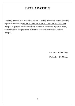
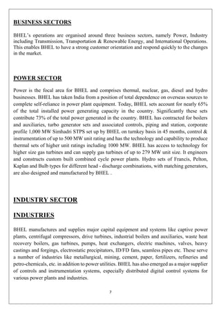
The final step in the process of casting usually involves grinding, sanding, or machining the
component in order to achieve the desired dimensional accuracies, physical shape, and surface
finish.
Removing the remaining gate material, called a gate stub, is usually done using
a grinder or sander. These processes are used because their material removal rates are slow
enough to control the amount of material being removed. These steps are done prior to any
final machining.
After grinding, any surfaces that require tight dimensional control are machined. Many
castings are machined in CNC milling centers. The reason for this is that these processes have
better dimensional capability and repeatability than many casting processes. However, it is not
uncommon today for castings to be used without machining.
A few foundries provide other services before shipping cast products to their customers. It is
common to paint castings to prevent corrosion and improve visual appeal. Some foundries
assemble castings into complete machines or sub-assemblies. Other foundries weld multiple
castings or wrought metals together to form a finished product.[3]
More and more, finishing processes are being performed by robotic machines, which eliminate
the need for a human to physically grind or break parting lines, gating material, or feeders.
Machines can reduce risk of injury to workers and lower costs for consumables — while also
increasing productivity. They also limit the potential for human error and increase repeatability
in the quality of grinding
Fig. Flowchart of a typical Foundary process](https://image.slidesharecdn.com/jaideepnewbhelproject-180331092607/85/BHEL-PROJECT-REPORT-TRAINING-REPORT-20-320.jpg)


![25
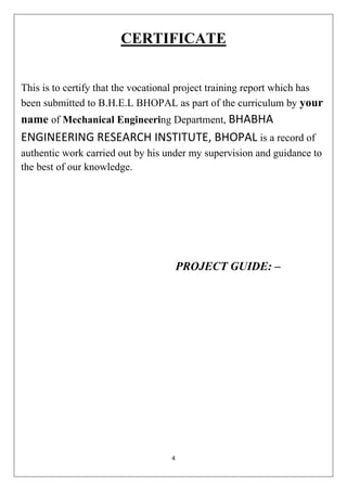
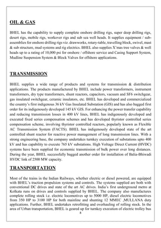
Francis Inlet Scroll, Grand Coulee Dam Small Swiss-made Francis turbine
Francis turbines may be designed for a wide range of heads and flows. This, along with their
high efficiency, has made them the most widely used turbine in the world. Francis type units
cover a head range from 40 to 600 m (130 to 2,000 ft), and their connected generator output
power varies from just a few kilowatts up to 800 MW.[2]
Large Francis turbines are
individually designed for each site to operate with the given water supply and water head at
the highest possible efficiency, typically over 90%.
KAPLAN TURBINE
The Kaplan turbine is a propeller-type water turbine which has adjustable blades. It was
developed in 1913 by Austrian professor Viktor Kaplan, who combined automatically
adjusted propeller blades with automatically adjusted wicket gates to achieve efficiency over
a wide range of flow and water level.](https://image.slidesharecdn.com/jaideepnewbhelproject-180331092607/85/BHEL-PROJECT-REPORT-TRAINING-REPORT-25-320.jpg)

![27
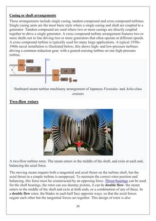
STEAM TURBINE SECTION
A steam turbine is a device that extracts thermal energy from pressurized steam and uses it
to do mechanical work on a rotating output shaft. Its modern manifestation was invented
by Sir Charles Parsons in 1884.
MANUFACTURING
The present-day manufacturing industry for steam turbines is dominated by Chinese power
equipment makers. Harbin Electric, Shanghai Electric, and Dongfang Electric, the top three
power equipment makers in China, collectively hold a majority stake in the worldwide
market share for steam turbines in 2009-10 according to Platts.[13]
Other manufacturers with
minor market share include Bhel, Siemens, Alstom, GE, Doosan Škoda Power, Mitsubishi
Heavy Industries, and Toshiba.[13]
The consulting firm Frost & Sullivan projects that
manufacturing of steam turbines will become more consolidated by 2020 as Chinese power
manufacturers win increasing business outside of China.
TYPES
Steam turbines are made in a variety of sizes ranging from small <0.75 kW (<1 hp) units
(rare) used as mechanical drives for pumps, compressors and other shaft driven equipment,
to 1 500 000 kW (1.5 GW; 2 000 000 hp) turbines used to generate electricity. There are
several classifications for modern steam turbines.
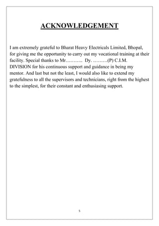
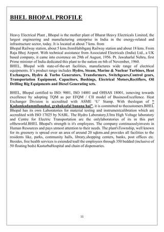
Blade and stage design
Schematic diagram outlining the difference between an impulse and a 50% reaction turbine](https://image.slidesharecdn.com/jaideepnewbhelproject-180331092607/85/BHEL-PROJECT-REPORT-TRAINING-REPORT-27-320.jpg)
![28
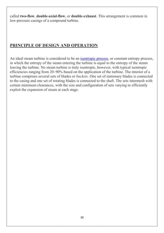
Turbine blades are of two basic types, blades and nozzles. Blades move entirely due to the
impact of steam on them and their profiles do not converge. This results in a steam velocity
drop and essentially no pressure drop as steam moves through the blades. A turbine
composed of blades alternating with fixed nozzles is called an impulse turbine, Curtis
turbine, Rateau turbine, or Brown-Curtis turbine. Nozzles appear similar to blades, but their
profiles converge near the exit. This results in a steam pressure drop and velocity increase as
steam moves through the nozzles. Nozzles move due to both the impact of steam on them
and the reaction due to the high-velocity steam at the exit. A turbine composed of moving
nozzles alternating with fixed nozzles is called a reaction turbine or Parsons turbine.Multiple
reaction stages divide the pressure drop between the steam inlet and exhaust into numerous
small drops, resulting in a pressure-compounded turbine. Impulse stages may be either
pressure-compounded, velocity-compounded, or pressure-velocity compounded. A pressure-
compounded impulse stage is a row of fixed nozzles followed by a row of moving blades,
with multiple stages for compounding. This is also known as a Rateau turbine, after its
inventor. A velocity-compounded impulse stage (invented by Curtis and also called a
"Curtis wheel") is a row of fixed nozzles followed by two or more rows of moving blades
alternating with rows of fixed blades. This divides the velocity drop across the stage into
several smaller drops.]
A series of velocity-compounded impulse stages is called a pressure-
velocity compounded turbine.
Blade Design Challenges
A major challenge facing turbine design is reducing the creep experienced by the blades.
Because of the high temperatures and high stresses of operation, steam turbine materials
become damaged through these mechanisms. As temperatures are increased in an effort to
improve turbine efficiency, creep becomes more significant. To limit creep, thermal coatings
and superalloys with solid-solution strengthening and grain boundary strengthening are used
in blade designs.
Refractory elements such as rhenium and ruthenium can be added to the alloy to improve
creep strength. The addition of these elements reduces the diffusion of the gamma prime
phase, thus preserving the fatigue resistance, strength, and creep resistance.
Steam supply and exhaust conditions
These types include condensing, non-condensing, reheat, extraction and induction.
Condensing turbines are most commonly found in electrical power plants. These turbines
receive steam from a boiler and exhaust it to a condenser. The exhausted steam is at a
pressure well below atmospheric, and is in a partially condensed state, typically of
a quality near 90%.
Reheat turbines are also used almost exclusively in electrical power plants. In a reheat
turbine, steam flow exits from a high-pressure section of the turbine and is returned to the
boiler where additional superheat is added. The steam then goes back into an intermediate
pressure section of the turbine and continues its expansion](https://image.slidesharecdn.com/jaideepnewbhelproject-180331092607/85/BHEL-PROJECT-REPORT-TRAINING-REPORT-28-320.jpg)

![32
Deviations from ideal
The ideal transformer model neglects the following basic linear aspects in real transformers.
Core losses, collectively called magnetizing current losses, consist of
Hysteresis losses due to nonlinear application of the voltage applied in the
transformer core, and
Eddy current losses due to joule heating in the core that are proportional to the square
of the transformer's applied voltage.
Whereas windings in the ideal model have no resistances and infinite inductances, the
windings in a real transformer have finite non-zero resistances and inductances associated
with:
Joule losses due to resistance in the primary and secondary windings
Leakage flux that escapes from the core and passes through one winding only resulting
in primary and secondary reactive impedance.
a
Leakage flux
The ideal transformer model assumes that all flux generated by the primary winding links all
the turns of every winding, including itself. In practice, some flux traverses paths that take it
outside the windings.[24]
Such flux is termed leakage flux, and results in leakage
inductance in series with the mutually coupled transformer windings.[10]
Leakage flux results
in energy being alternately stored in and discharged from the magnetic fields with each cycle
of the power supply. It is not directly a power loss, but results in inferior voltage regulation,
causing the secondary voltage not to be directly proportional to the primary voltage,
particularly under heavy load.[24]
Transformers are therefore normally designed to have very
low leakage inductance.
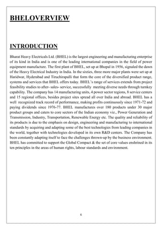
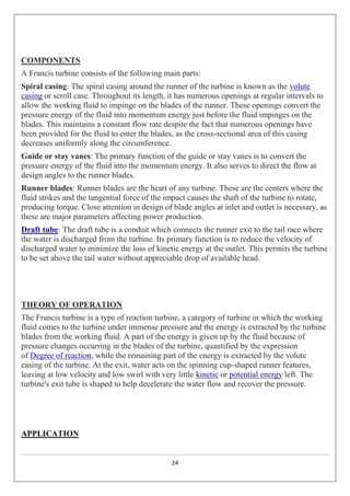
Equivalent circuit
Referring to the diagram, a practical transformer's physical behavior may be represented by
an equivalent circuit model, which can incorporate an ideal transformer.](https://image.slidesharecdn.com/jaideepnewbhelproject-180331092607/85/BHEL-PROJECT-REPORT-TRAINING-REPORT-32-320.jpg)


![35
Transformers for use at power or audio frequencies typically have cores made of high
permeability silicon steel. The steel has a permeability many times that of free space and the
core thus serves to greatly reduce the magnetizing current and confine the flux to a path which
closely couples the windings.Early transformer developers soon realized that cores
constructed from solid iron resulted in prohibitive eddy current losses, and their designs
mitigated this effect with cores consisting of bundles of insulated iron wires. Later designs
constructed the core by stacking layers of thin steel laminations, a principle that has remained
in use. Each lamination is insulated from its neighbors by a thin non-conducting layer of
insulation. The universal transformer
Solid cores
Powdered iron cores are used in circuits such as switch-mode power supplies that operate
above mains frequencies and up to a few tens of kilohertz. These materials combine high
magnetic permeability with high bulk electrical resistivity. For frequencies extending beyond
the VHF band, cores made from non-conductive magnetic ceramic materials
called ferrites are common.Some radio-frequency transformers also have movable cores
(sometimes called 'slugs') which allow adjustment of the coupling
coefficient (and bandwidth) of tuned radio-frequency circuits.
Air cores
A physical core is not an absolute requisite and a functioning transformer can be produced
simply by placing the windings near each other, an arrangement termed an 'air-core'
transformer. The air which comprises the magnetic circuit is essentially lossless, and so an
air-core transformer eliminates loss due to hysteresis in the core material.[10]
The leakage
inductance is inevitably high, resulting in very poor regulation, and so such designs are
unsuitable for use in power distribution.They have however very high bandwidth, and are
frequently employed in radio-frequency applications, for which a satisfactory coupling
coefficient is maintained by carefully overlapping the primary and secondary windings.
They're also used for resonant transformers such as Tesla coils where they can achieve
reasonably low loss in spite of the high leakage inductance.](https://image.slidesharecdn.com/jaideepnewbhelproject-180331092607/85/BHEL-PROJECT-REPORT-TRAINING-REPORT-35-320.jpg)
![36
Windings
The conducting material used for the windings depends upon the application, but in all cases
the individual turns must be electrically insulated from each other to ensure that the current
travels throughout every turn.[62]
For small power and signal transformers, in which currents
are low and the potential difference between adjacent turns is small, the coils are often wound
from enamelled magnet wire, such as Formvar wire. Larger power transformers operating at
high voltages may be wound with copper rectangular strip conductors insulated by oil-
impregnated paper and blocks of pressboard.
Cooling
Cutaway view of liquid-immersed construction transformer. The conservator (reservoir) at
top provides liquid-to-atmosphere isolation as coolant level and temperature changes. The
walls and fins provide required heat dissipation balance.
See also: Arrhenius equation
To place the cooling problem in perspective, the accepted rule of thumb is that the life
expectancy of insulation in all electrics, including all transformers, is halved for about every
7 °C to 10 °C increase in operating temperature, this life expectancy halving rule holding
more narrowly when the increase is between about 7 °C to 8 °C in the case of transformer
winding cellulose insulation.
Small dry-type and liquid-immersed transformers are often self-cooled by natural convection
and radiation heat dissipation. As power ratings increase, transformers are often cooled by
forced-air cooling, forced-oil cooling, water-cooling, or combinations of these.Large
transformers are filled with transformer oil that both cools and insulates the
windings. Transformer oil is a highly refined mineral oil that cools the windings and
insulation by circulating within the transformer tank. The mineral oil and paper insulation
system has been extensively studied and used for more than 100 years.
Insulation drying
Construction of oil-filled transformers requires that the insulation covering the windings be
thoroughly dried of residual moisture before the oil is introduced. Drying is carried out at the
factory, and may also be required as a field service. Drying may be done by circulating hot](https://image.slidesharecdn.com/jaideepnewbhelproject-180331092607/85/BHEL-PROJECT-REPORT-TRAINING-REPORT-36-320.jpg)
![37
air around the core, or by vapor-phase drying (VPD) where an evaporated solvent transfers
heat by condensation on the coil and core.
For small transformers, resistance heating by injection of current into the windings is used.
The heating can be controlled very well, and it is energy efficient. The method is called low-
frequency heating (LFH) since the current used is at a much lower frequency than that of the
power grid, which is normally 50 or 60 Hz. A lower frequency reduces the effect of
inductance, so the voltage required can be reduced. The LFH drying method is also used for
service of older transformers.
Bushings
Larger transformers are provided with high-voltage insulated bushings made of polymers or
porcelain. A large bushing can be a complex structure since it must provide careful control
of the electric field gradient without letting the transformer leak oil.[84]
Classification parameters
Transformers can be classified in many ways, such as the following:
Power capacity: From a fraction of a volt-ampere (VA) to over a thousand MVA.
Duty of a transformer: Continuous, short-time, intermittent, periodic, varying.
Frequency range: Power-frequency, audio-frequency, or radio-frequency.
Voltage class: From a few volts to hundreds of kilovolts.
Cooling type: Dry and liquid-immersed – self-cooled, forced air-cooled; liquid-
immersed – forced oil-cooled, water-cooled.
Types
Various specific electrical application designs require a variety of transformer types.
Although they all share the basic characteristic transformer principles, they are customize in
construction or electrical properties for certain installation requirements or circuit conditions.
Autotransformer: Transformer in which part of the winding is common to both primary
and secondary circuits, leading to increased efficiency, smaller size, and a higher degree of
voltage regulation.[89][90]
Capacitor voltage transformer: Transformer in which capacitor divider is used to
reduce high voltage before application to the primary winding.
Distribution transformer, power transformer: International standards make a
distinction in terms of distribution transformers being used to distribute energy from
transmission lines and networks for local consumption and power transformers being used to
transfer electric energy between the generator and distribution primary circuits.[89][91][q]
Phase angle regulating transformer: A specialised transformer used to control the flow
of real power on three-phase electricity transmission networks.
Scott-T transformer: Transformer used for phase transformation from three-phase
to two-phase and vice versa.](https://image.slidesharecdn.com/jaideepnewbhelproject-180331092607/85/BHEL-PROJECT-REPORT-TRAINING-REPORT-37-320.jpg)
![38
Polyphase transformer: Any transformer with more than one phase.
Grounding transformer: Transformer used for grounding three-phase circuits to create
a neutral in a three wire system, using a wye-delta transformer, or more commonly, a zigzag
grounding winding.
Leakage transformer: Transformer that has loosely coupled windings.
Resonant transformer: Transformer that uses resonance to generate a high secondary
voltage.
Audio transformer: Transformer used in audio equipment.
Output transformer: Transformer used to match the output of a valve amplifier to its
load.
Instrument transformer: Potential or current transformer used to accurately and safely
represent voltage, current or phase position of high voltage or high power circuits.
Pulse transformer: Specialized small-signal transformer used to transmit digital
signaling while providing electrical isolation, commonly used in Ethernet computer networks
as 10BASE-T, 100BASE-T and 1000BASE-T.
Applications
Transformer at the Limestone Generating Station in Manitoba, Canada
Transformers are used to increase (or step-up) voltage before transmitting electrical energy
over long distances through wires. Wires have resistance which loses energy through joule
heating at a rate corresponding to square of the current. By transforming power to a higher
voltage transformers enable economical transmission of power and distribution.
Consequently, transformers have shaped the electricity supply industry, permitting
generation to be located remotely from points of demand.[94]
All but a tiny fraction of the
world's electrical power has passed through a series of transformers by the time it reaches the
consumer.[44]](https://image.slidesharecdn.com/jaideepnewbhelproject-180331092607/85/BHEL-PROJECT-REPORT-TRAINING-REPORT-38-320.jpg)