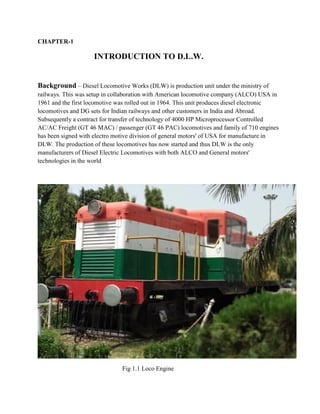
result management system report for college project
Dlw report for electronic communication engineering
1. SUMMER TRAINING REPORT
ON
Diesel Locomotive works,Varanasi
Submitted in partial fulfillment of the
Requirement for the award of the
Degree of
BACHELOR OF TECHNOLOGY
In
Electronics Engineering
by
Vaibhav Kumar
Dr. Ambedkar Institute of Technology For Handicapped Kanpur
Abdul Kalam Technical University (UP)
June 2018
2. Contents
ABSTRACT
ACKNOWLEDGEMENT
CHAPTER-1
Introduction Of DLW
CHAPTER-2
Maintenance Service Shop
2.1 Winding Shop
2.2 Electronic Lab
2.3 Overhauling
CHAPTER-3
Telephone Exchange
3.1 Types Of Exchanges
3.2 Telephone Exchange In DLW
3.3 Internal Distribution Frame
3.4 Main Distribution Frame
3.5 Distribution Board
3.6 Types Of Standard Tones
3.7 Signaling
3.8 Fault
CHAPTER-4
Supervisory Control And Data Acquisition(SCADA)
4.1 Major Components Of SCADA
4.2 Types Of SCADA System
4.3 Control System Used In DLW
CHAPTER-5
Loco Testing Shop
Reference
3. ACKNOWLEDGEMENT
I would sincerely like to thank the employees and the officers of
DLW, VARANASI for their help and support during the vocational training.
Despite their busy schedules, they took time out and explained to us the various
aspects of the working of the plant and technological knowhow.
I would sincerely like to thank Shri Amit Kumar (ACWI/Elect.),
Miss. Ratna Singh (SSE/Telephone Exchange) and other JEs who were
instrumental in arranging the vocational training at DLW Varanasi, and without
whose help and guidance the training could not have materialized.
I express my deep sense of gratitude to the Principal, TTC for given
me such a great opportunity.
4. ABSTRACT
The industrial training report of DLW (DIESEL LOCOMOTIVE
WORKS) is various trade. i.e. Electronics and communication, Electrical,
Mechanical, Electrical & Electronics and many engineering holders are
participated. The content of my industrial topic Maintenance Service Shop, Loco
Test Shop, Telephone Exchange and Supervisory Control And Data Acquisition.
we are discus about how to communicate the singal from transmitter to receiver.
The second is LTS (Loco Testing Shop), I learn about testing of loco engine. After
completed the Loco Testing Shop going to discuss about Maintenance Service
Shop. Than the last of my section is SCADA, in this shop I learn the controlling of
whole industrial and data through software.This report is written on the basis of
practical knowledge of acquired by me during the period of practical training taken
at, Diesel Locomotive Works Varanasi. This report is presented in very simple &
understanding language and it is comprise of four sections namely Telephone
Exchange, Maintenance Service Shop, Supervisory Control And Data Acquisition
and Loco Testing Shop
5. CHAPTER-1
INTRODUCTION TO D.L.W.
Background – Diesel Locomotive Works (DLW) is production unit under the ministry of
railways. This was setup in collaboration with American locomotive company (ALCO) USA in
1961 and the first locomotive was rolled out in 1964. This unit produces diesel electronic
locomotives and DG sets for Indian railways and other customers in India and Abroad.
Subsequently a contract for transfer of technology of 4000 HP Microprocessor Controlled
AC/AC Freight (GT 46 MAC) / passenger (GT 46 PAC) locomotives and family of 710 engines
has been signed with electro motive division of general motors' of USA for manufacture in
DLW. The production of these locomotives has now started and thus DLW is the only
manufacturers of Diesel Electric Locomotives with both ALCO and General motors'
technologies in the world
Fig 1.1 Loco Engine
6. Brief History
Set up in 1961 as a green-field project in technical collaboration with ALCO/USA to
Manufacture Diesel Electric Locomotives. First locomotive rolled out and dedicated to nation in
January, 1964. Transfer-of-Technology agreement signed with General Motors/ USA in
October, 95 to manufacture state-of-the-art high traction AC-AC diesel locomotives.
A flagship company of Indian Railways offering complete range of flanking products
in its area of operation. State-of-the art Design and Manufacturing facility to manufacture more
than 150 locomotives per annum with wide range of related products viz. components and sub-
assemblies. Unbeatable trail-blazing track record in providing cost-effective, eco-friendly and
reliable solutions to everincreasing transportation needs for over three decades. Fully geared to
meet specific transportation needs by putting Price Value-Technology equation perfectly right.
A large base of delighted customers among many countries viz. Sri Lanka, Malaysia,
Vietnam, Bangladesh, Tanzania to name a few, bearing testimony to product leadership in its
category.
Fig 1.2 Workshop area of DLW
7. CHAPTER-2
Maintenance Service Shop
Introduction
Maintenance, repair, and overhaul involve fixing any sort of mechanical,
plumbing or electrical device should it become out of order or broken (known as repair,
unscheduled, or casualty maintenance). It also includes performing routine actions which keep
the device in working order (known as scheduled maintenance) or prevent trouble from arising
(preventive maintenance). MRO may be defined as, "All actions which have the objective of
retaining or restoring an item in or to a state in which it can perform its required function. The
actions include the combination of all technical and corresponding administrative, managerial,
and supervision actions.
Fig. 2.1 Maintenance shop of DLW
MSS is the unit in which Maintenance & repair the device that include:
1. Winding shop
2. Electronics lab
3. Overhauling
4. Air Conditioning
8. 2.1 winding shop
A step motor is a constant output power transducer, where power is defined as
torque multiplied by speed. This means motor torque is the inverse of motor speed. To
help understand why a step motor’s power is independent of speed, we need to construct
(figuratively) an ideal step motor,
An ideal step motor would have zero mechanical friction, its torque would be
proportional to ampere-turns and its only electrical characteristic would be inductance.
Ampere-turns simply mean that torque is proportional to the number of turns of wire in
the motor’s stator multiplied by the current passing through those turns of wire.
Anytime there are turns of wire surrounding a magnetic material such as the iron
in the motor’s stator, it will have an electrical property called inductance. Inductance
describes the energy stored in a magnetic field anytime current passes through this coil of
wire.
Fig.2.2 Internal part of 3-phase moter
2.2 Electronics lab
There is a full-fledged Electronic Lab to cater to maintenance need of highly
sophisticated CNC machines and component / subassembly level trouble shooting of PCBs,
9. Servo Drives, and Microprocessor based controllers and electronic units. This Lab also supports
other Zonal Railways in repair of PCBs.
Important Machines:
(i) Reverse Engineering System: It helps tracing PCB tracks between components in
given circuit board whose detail is not provided by the OEM.
(ii) Automatic Test Equipment: With its library having more than 30,000 components
details, it helps in-circuit testing of digital and analog devices mounted on latest PCBs.
2.2.1 MULTIMETER
A multimeter or a multitester, also known as a VOM (Volt-Ohm meter), is an electronic
measuring instrument that combines several measurement functions in one unit. A typical
multimeter would include basic features such as the ability to measure voltage, current, and
resistance. Analog multimeters use a microammeter whose pointer moves over a scale calibrated
for all the different measurements that can be made.
Digital multimeters (DMM, DVOM) display the measured value in numerals, and may
also display a bar of a length proportional to the quantity being measured. Digital multimeters
are now far more common than analog ones, but analog multimeters are still preferable in some
cases, for example when monitoring a rapidlyvarying value.
Fig.2.3 Multimeter
10. 2.2.2 CAPACITOR
A capacitor ( known as a condenser) is a passive two-terminal electrical component used
to store energy electro statically in an electric field.Capacitors are widely used in electronic
circuits for blocking direct current while allowing alternating current to pass. In analog filter
networks, they smooth the output of power supplies. In resonant circuits they tune radios to
particular frequencies. In electric power transmission systems they stabilize voltage and power
flow.
Fig.2.4 Electrolytic capacitors of different voltages and capacitance
2.2.3 TRANSISTOR
A transistor is a semiconductor device used to amplify and switch electronic signals and
electrical power. It is composed of semiconductor material with at least three terminals for
connection to an external circuit. A voltage or current applied to one pair of the transistor's
terminals changes the current through another pair of terminals. Because the controlled (output)
power can be higher than the controlling (input) power, a transistor can amplify a signal. Today,
some transistors are packaged individually, but many more are found embedded in integrated
circuits.
2.2.4 RESISTANCE
The electrical resistance of an electrical conductor is the opposition to the passage of an
electric current through that conductor; the inverse quantity is electrical conductance, the ease at
which an electric current passes.
2.2.5 SOLDERING AND DESOLDERING
Soldering is a process in which two or more metal items are joined together by melting
and flowing a filler metal (solder) into the joint, the filler metal having a lower melting point
11. than the work piece. In electronics, desoldering is the removal of solder and components from a
circuit board for troubleshooting, repair, replacement, and salvage. Specialized tools, materials,
and techniques have been devised to aid in the desoldering process.
Fig.2.5 Soldering Process
2.3 OVERHAULING
Overhauling of machine is defined as a process of
general maintenance performed on a machine or other industrial equipment. The goal
of overhauling is to keep the system in serviceable condition. Regular checks can
prevent all kinds of critical damage.
12. CHAPTER-3
TELEPHONE EXCHANG
A telephone exchange is a telecommunications system used in the public
switched telephone network or in large enterprises. An exchange consists of electronic
components and in older systems also human operators that interconnect (switch) telephone
subscriber lines or virtual circuits of digital systems to establish telephone calls between
subscribers. In the public telecommunication networks a telephone exchange is located in a
central office (CO), typically a building used to house the inside plant equipment of potentially
several telephone exchanges, each serving a certain geographical exchange area. Central office
locations are often identified in North America as wire centres, designating a facility from which
a telephone obtains dial tone. For business and billing purposes, telephony carriers also define
rate centres, which in larger cities may be clusters of central offices, to define specified
geographical locations for determining distance measurements. In the United States and Canada,
the Bell System established in the 1940s a uniform system of identifying each telephone
exchange with a three-digit exchange code, or central office code, that was used as a prefix to
subscriber telephone numbers. All exchanges within a larger region, typically aggregated by
state, were assigned a common area code. With the development of international and
transoceanic telephone trunks, especially driven by direct customer dialing, similar efforts of
systematic organization of the telephone networks occurred in many countries in the mid-20th
century.
3.1 TYPES OF EXCHANGES
3.1.1 LOCAL EXCHANGE
Local exchanges service the subscribers within a particular area e.g. a district of a city or
a locality. They switch incoming traffic to and outgoing traffic from the connected subscriber.
The number of subscribers connected to an EWSD exchange can be as low as a few hundred or
as high as 250000.
3.1.2 TRANSIT EXCHANGE
At node points in the telephone network transit exchanges connect together trunks to and
from other exchanges up to 60,000 incoming outgoing or both ay trunks can be connected to
EWSD transit or long distance exchanges.
3.1.3 LOCAL TRANSIT EXCHANGE
13. These exchanges handle transit or long distance traffic as well as incoming and outgoing
local traffic. Any number of subscriber lines and trunks can be combined within the maximum
traffic handling capabilities of the exchange. Within the above mentioned local and transit
exchange capacity limits, any combination of subscriber lines and trunks can be connected, as
well as the limit of 25,000 elands is not exceeded.
3.2 TELEPHONE EXCHANG IN D.L.W.
▪ Provides telephone connections to the D.L.W. administrative blocks and D.L.W. colony area.
▪ This exchange is also provided by the rack type Main Distribution Board (MDF). This has
capacity to mount the fuse mounting with fuses and test jacks.
▪ This exchange is designed to perform satisfactorily for a line loop resistance of 100 ohms for
each subscriber.
▪ The local loop is the physical loop or circuit that connects from the demarcation point of the
customer premises to the edge of the telecommunication service provider‘s network.
▪ The exchange works on the D.C. supply of 50 volts obtained from the battery set which is
connected in parallel to the charger which is operating on 230 volts A.C.
▪ The voltage required when two subscriber talks is 12 volts.
3.2.1 BATTERY CHARGER
It operates at 230v ac and then converted to 48-50v dc and provided to the exchange. Battery is
connected in parallel as soon as the electricity goes off and the exchange gets connected to the
battery.
1- AC & DC both supply come.
2- Works on AC power until the supply is there.
3- When supply goes off it starts working on DC.
3.3 INTERNAL DISTRIBUTION FRAME(IDF)
In IDF the framing of jumper is done. The cables which are coming out of exchange are
terminated in IDF. In IDF the numbers are connected in series wire and thus it makes easier to
find out the number in the IDF whenever some complication arise. In Railway Telephone
exchange there are two type of IDF-
1- Crown type installed by the Tata Company
2- Block type installed just beside the MDF
14. Fig.3.1 IDF
3.4 MAIN DISTRIBUTION FRAME
The exchange is also provided in the Rack type of Tag Block, which is called
MDF.In MDF we mount the fuse hold tag at the back of the Block and at the front of the Jumper.
There are 40 Blocks in a single frame where 20 are of B side making the number B1-B20 and
other 20 are on the F side making with F1-F20. In MDF the numbers are distributed here and
then according to distribution of the cables the record of the numbers is maintained. Installation
of the Tag Block in the MDF makesit easier to find the fault between MDF and IDF.
Fig.3.2 MDF
15. 3.5 DISTRIBUTION BOARD
It is a box type board in which cable pads are distributed according to the
number which are to be provided near the distribution. DB are installed after a certain interval of
the distance making a proper distribution of cable which is easier with the consumers.
Fig.3.3 Distribution board
3.6 TYPES OF STANDERD TONES
▪ Busy Tone (BT)-Engage tone or busy tone I tone which dialer hear due to engage of call.
400Hz applied for 0.75sec and disconnected for 0.75sec.
▪ Number Unobtainable (NU)-400Hz applied continuously 2.5sec on and 0.5sec off.
▪ Ringing Tone- It is the ring which we hear on calling.133Hz interrupted at the same frequency
at the ringing current.
▪ Dial Tone- It is the continuous tone which we hear on incoming call at dialer’s end. 33Hz
applied continuously.
16. 3.7 SIGNALING
The sending of a signal from the transmitting end of a telecommunication circuit to inform that
user at the receiving end that a message is to be sent.
There are three types of signaling used in India-
▪ Ring Down (RD) signaling
▪ Loop Disconnect (LD) signaling
▪ Open Dialing (OD) signaling
3.8 FAULT
▪ Line Contact- It means that the drop wire is connected either with a pole or a tree if it is
broken down, a husky voice is obtained when we ring.
▪ Line Earth- It means that drop wire breaks on its own when it touches a pole or a tree. A soft
humming sound comes when we dial a number.
▪ Line Disc- The wire has been broken down.
17. CHAPTER-4
SUPERVISORY CONTROL AND DATA ACQUISITION(SCADA)
SCADA is a system for remote monitoring and control that operates with coaded
signals over communication channels “using typically one communication channel per remote
station”. It is an industrial computer-based control system employed to gather and analyze the
real-time data to keep, track, monitor and control industrial equipments in different types of
industries.
SCADA in power system can be defined as the power distribution application which is
typically based on the software package. The electrical distribution system consist of several
substations; these substation will have multiple number of sensors, controllers and operator-
interface points.
Fig.4.1 SCADA system
The major function of SCADA is for acquiring data from remote devices such
asvalves, pumps, transmitters etc. and providing overall control remotely from aSCADA Host
software platform. This provides process control locally so thatthese devices turn on and off at
the right time, supporting your control strategyand a remote method of capturing data and events
(alarms) for monitoring theseprocesses. SCADA Host platforms also provide functions for
graphical displays,alarming, trending and historical storage of data.
Historically, SCADA products have been produced that are generic with a ‘oneshoe
fits all’ approach to various markets. As SCADA has matured to providespecific solutions to
specific SCADA markets it has provided solutions for widearea network SCADA systems that
rely on tenuous communication links.
18. 4.1 MAJOR COMPONENT OF SCADA
▪ Field instrumentation
▪ Programmable Logic Controllers/Remote Terminal Unit
▪ Communication network
▪ SCADA host software
Fig.4.2 Component of SCADA
4.1.1 FIELD INSTRUMENTATION
Instrumentation is a key component of safe and optimized control system. Traditionally
operator controlled the devices manually , now a days instruments would have been fitted with
feedback sensors such as limit switches, providing connectivity from these devices into a local
P.L.C.s and R.T.U. , to relay data to the SCADA host software.
SENSOR AND END DEVICES
Sensors detect and transmit readings of important parameters to P.L.C.s. End devices
include equipments from valves to large machinery like pump, supply and industrial chillers are
controlled by the PLCs to start, stop and function as required.
4.1.2 P.LC.s
PLCs are electronic brains that scan thousands of rungs or lines of custom code to
execute predetermined logic based on the inputs from the readings of the sensors in order to
control the outputs which are the end devices of the plant. These normally happens
autonomously without requiring input from operator. These are sometimes called Process
Automation Controllers(PAC) or may have close cousins called Remote Terminal Units(RTU).
19. Fig.4.3 PLCs
PLCs are used instead of RTUs because of the advantages of PLCs like flexibility,
configuration, versatile and affordability compared to RTUs.
R.T.Us
Physical objects in the SCADA systems are interfaced with the microprocessor
controlled electronic devices called as Remote Terminal Units (RTUs). These units are used to
transmit telemetry data to the supervisory system and receive the messages from the master
system for controlling the connected objects. Hence, these are also called as Remote Telemetry
Units.
4.1.3COMMUNICATION NETWORK
Generally the combination of radio and direct wired connections is used for SCADA
systems, but in case of large systems like power stations and railways SONET/SDH are
frequently used. Among the very compact SCADA protocols used in SCADA systems – a few
communication protocols, which are standardized and recognized by SCADA vendors – send
information only when the supervisory station polls the RTUs.
I/O SERVER
I/O server are computers that communicate to PLCs via industrial Ethernet to obtain the
sensor values as well as other representative data of the status of the processes in the plant or
facility and further distributes them to the operator stations and historian.
HISTORIAN
The historian is normally a server with a large hard disk capacity to log reading of the
sensors as well as other plant data, alarms and event logs. For smaller systems, the I/O
servers,operator stations and historian can be the same desktop computer.
20. 4.2 TYPES OF SCADA SYSTEM
There are different types of SCADA systems that can be considered as SCADA
architectures of four different generations:
▪ First Generation: Monolithic or Early SCADA systems,
▪ Second Generation: Distributed SCADA systems,
▪ Third Generation: Networked SCADA systems and
▪ Fourth Generation: Internet of things technology, SCADA systems
EARLY SCADA SYSTEM
All the remote terminal unit sites would connect to a back-up mainframe system for
achieving the first generation SCADA system redundancy, which was used in case of failure of
the primary mainframe system. The functions of the monolithic SCADA systems in the early
first generation were limited to monitoring sensors in the system and flagging any operations in
case of surpassing programmed alarm levels.
Fig.4.4 Early SCADA system
DISTRIBUTED SCADA SYSTEM
In the second generation, the sharing of control functions is distributed across the
multiple systems connected to each other using Local Area Network (LAN). Hence, these were
termed as distributed SCADA systems. These individual stations were used to share real-time
information and command processing for performing control tasks to trip the alarm levels of
possible problems.
21. Fig.4.5 Distributed SCADA system
NETWORKED SCADA SYSTEM
The current SCADA systems are generally networked and communicate using Wide
Area Network (WAN) Systems over data lines or phone. These systems use Ethernet or Fiber
Optic Connections for transmitting data between the nodes frequently. These third generation
SCADA systems use Programmable Logic Controllers (PLC) for monitoring and adjusting the
routine flagging operators only in case of major decisions requirement.
Fig.4.6 Network SCADA system
INTERNET OF THINGS
In fourth generation, the infrastructure cost of the SCADA systems is reduced by
adopting the internet of things technology with the commercially available cloud
computing. The maintenance and integration is also very easy for the fourth generation
compared to the earlier SCADA systems.
22. Fig.4.7 Internet of things
4.3 CONTROL SYSTEM USED IN D.L.W.
Fig.4.8 Control system
FUNCTIONS
▪ SUPERVISION OF THE COMPLETE SUBSTATIONS - Graphical display of
measurement values, positions of breakers, alarm management, trending management,
disturbance.
▪ COMMAND- Command of all motorized devices including MV breakers and DC
breakers.
▪ PARAMETERIZATION- Parameter setting of all protection relays.
▪ CONTROL- Possibility to define special control sequences.
23. CHAPTER-5
LOCO TESTING SHOP
When all the perform are done then finally engine come in ETS, for the first inspection
report and after this it will be agreed for the performance
Testing of the final locomotive on the basis of several performance
1. Initial filling of lube oil (approx. 4200 ltr)
2. Filling of all fuel (approx. 3000 ltr)
3. Load testing
4. Testing of MR1 and MR2
5. Air brake testing
6. Water circuit check
7. Testing of dynamic brake
8. Lightning inspection
9. Testing of the speed
Fig. Loco Engine Testing