The document provides information about the industrial training completed by Ashish Patidar at Seldom India from November 26, 2014 to January 17, 2015. It discusses the aims and objectives of the training, which were to gain knowledge in electrical engineering concepts. It also describes Seldom India, the company where the training took place, including its vision, products, and services in automation, control, and instrumentation. The schedule of the 45-day training program is outlined.


![B. Tech., Electrical Engineering Seldom India
13 Poornima University,Jaipur
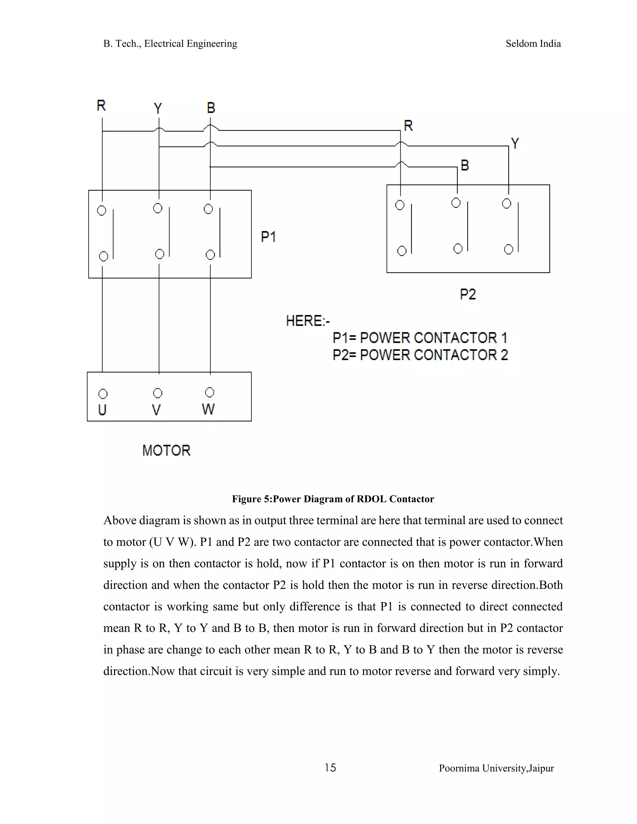
3.4 RDOL (Reverse Direct Online Starter)
3.4.1 Introduction
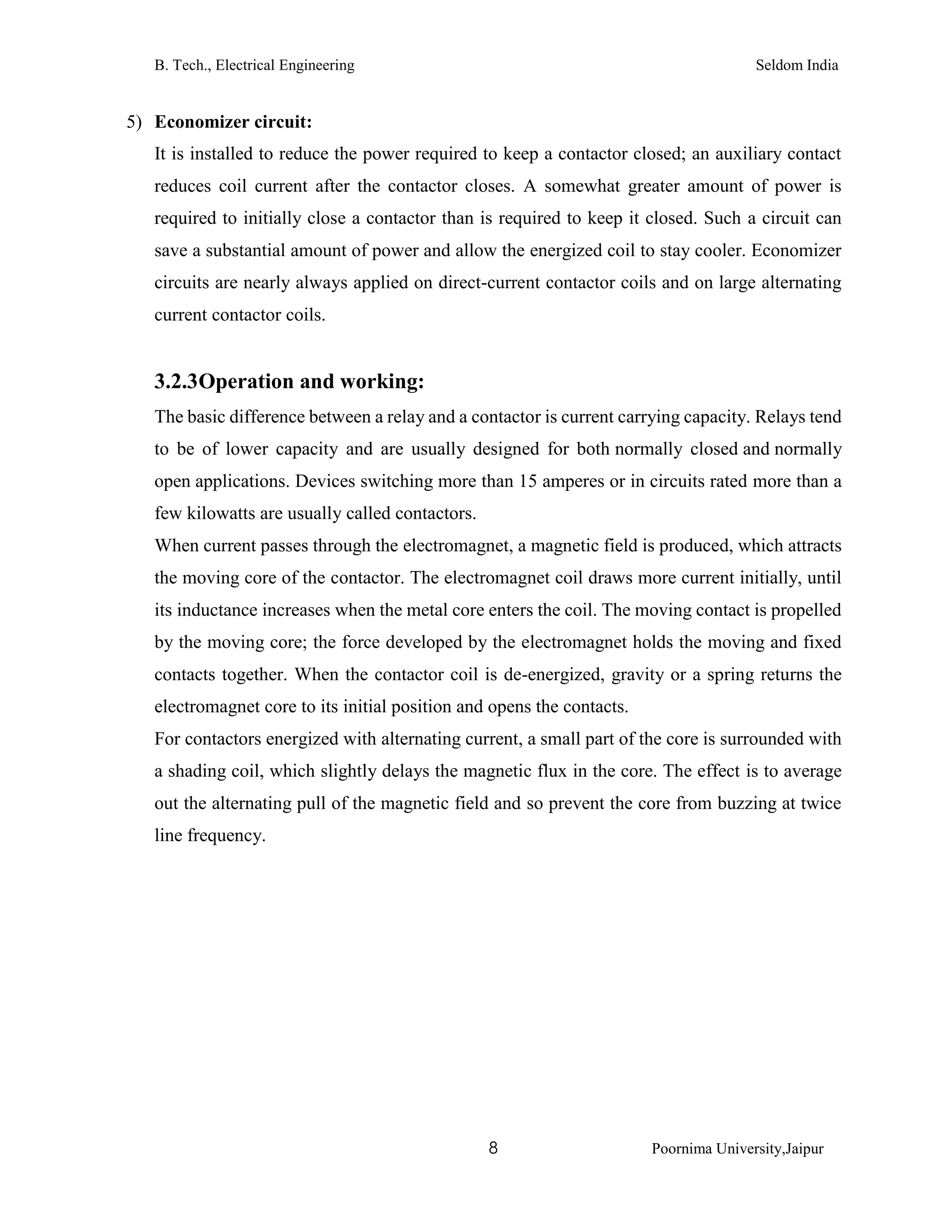
“RDOL [Reversible DOL] starters are simply two DOL starters in the same box and
allow the motor to be started in one direction then in the other direction”.
Figure 3:Practical Diagram of RDOL Circuit](https://image.slidesharecdn.com/ebd3d414-5348-4f4e-a318-cbfe089adfa3-150710173150-lva1-app6892/75/training-report-25-2048.jpg)
![B. Tech., Electrical Engineering Seldom India
14 Poornima University,Jaipur
3.4.2 Principle and working
RDOL made to two DOL circuit in series, both terminal of A2 are shorted to each other
and that point it’s called natural. Do the interlocking between both DOL circuits.
Interlocking are very important to both DOL circuit because if you are worked in at a time
only one contactor then will we use interlocking. RDOL circuit are also used to run motor
in forward and reverse direction.
Figure 4:Control Diagram of RDOLwith Contactors
RDOL [Reversible DOL] starters are simply two DOL starters in the same box and allow
the motor to be started in one direction and then in the other direction. Assume that we are
talking about three phase motors. Suppose a sheet-metal goods factory uses a 10 kW motor
to drive a set of rollers. When sheet metal goods are being made, it is sometimes necessary
to roll the sheet metal in one direction and then the other.](https://image.slidesharecdn.com/ebd3d414-5348-4f4e-a318-cbfe089adfa3-150710173150-lva1-app6892/75/training-report-26-2048.jpg)