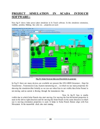
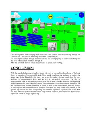
The document provides details about an internship project on PLC, SCADA and automation completed by Varun Kumar Raghav at Sofcon India Pvt. Ltd. It includes an acknowledgement, abstract, certificate of completion, table of contents and chapters covering company profile, introduction to automation, PLC programming and operation, SCADA software and applications. The internship helped provide hands-on experience with PLC and SCADA systems and their uses in industrial automation.
![[i]
INDUSTRIAL TRAINING AND PROJECT REPORT
On
PLC SCADA AND AUTOMATION
BY
VARUN KUMAR RAGHAV (1703221107)
SUBMITTED TO THE DEPARTMENT OF ELECTRICAL AND ELECRONICS ENGINEERINGIN
PARTIAL FULFILLMENT OF THE REQUIREMENS
FOR THE DEGREE OF BACHELOR OF
TECHNOLOGY
IN
ELECTRICAL AND ELECRONICS ENGINEERINGING
ABES Engineering college Ghaziabad
Dr. APJ Abdul Kalam technical university Uttar Pradesh Lucknow](https://image.slidesharecdn.com/finalrepotofsummerinternship-201001035954/85/summer-internship-report-on-PLC-SCADA-1-320.jpg)
![[i]
INDUSTRIAL TRAINING AND PROJECT REPORT
On
PLC SCADA AND AUTOMATION
BY
VARUN KUMAR RAGHAV (1703221107)
SUBMITTED TO THE DEPARTMENT OF ELECTRICAL AND ELECRONICS ENGINEERINGIN
PARTIAL FULFILLMENT OF THE REQUIREMENS
FOR THE DEGREE OF BACHELOR OF
TECHNOLOGY
IN
ELECTRICAL AND ELECRONICS ENGINEERINGING
ABES Engineering college Ghaziabad
Dr. APJ Abdul Kalam technical university Uttar Pradesh Lucknow](https://image.slidesharecdn.com/finalrepotofsummerinternship-201001035954/75/summer-internship-report-on-PLC-SCADA-1-2048.jpg)
![[ii]
ACKNOWLEDGEMENT
I feel profound happiness in forwarding this industrial training report as an image
of sincere efforts. It is almost inevitable to ensure indebtedness to all who
generously helped by sharing their valuable experience & devoting their precious
time with us, without whom this seminar report would have never been
accomplished.
First & foremost I extend my thanks & gratitude to the entire unit of “SOFCON
INDIAN PVT.LTD. NOIDA” along with “Mr. PUSHKAR BAJPAYEE
(DIRECTOR)”,“Mr. PRAVEEN KUMAR (Assistant Professor)” whose
guidance, teaching and invaluable suggestions provided me a deep insight in my
chosen field of technology, enhanced my knowledge and supported in widening
my outlook towards the communication industry. I am also very thankful to all the
engineers of the department for their kind support throughout the training.](https://image.slidesharecdn.com/finalrepotofsummerinternship-201001035954/85/summer-internship-report-on-PLC-SCADA-2-320.jpg)
![[iii]
ABSTRACT
Industrial training is must for every student perusing professional degree because
the ultimate goal of every student is to get the information the industrial training
helps us to get an idea of the things. We should know in order to get a job i.e. I
have a good professional career. Industrial training teaches us lots of things. it
helps us to know the kind of environment we would be getting in the industry and
help us to get with the kind of environment. The totality the industrial teaches us
industrial ethics. Some advance technical how and help us to acquire with
industrial working style. Supervisory control and data acquisition (SCADA) allows
a utility operator to monitor and control processes that are distributed among
various remote sites. SCADA, is a system for gathering real time data, controlling
processes, and monitoring equipment from remote locations. As more companies
are implementing an open SCADA architecture through the Internet to monitor
critical infrastructure components such as power plants, oil and gas pipelines,
chemical refineries, flood control dams, and waste and water systems, vital
systems are becoming increasingly open to attack. This report provides an
overview of SCADA, outlines several vulnerabilities of SCADA systems, presents
data on known and possible threats, and provides particular remediation strategies
for protecting these systems. PLCs are used in many different industries and
machines such as packaging and semiconductor machines. Programs to control
machine operation are typically stored in battery-backed or non-volatile memory.
A programmable logic controller (PLC) or programmable controller is a digital
computer used for automation of electromechanical processes, such as control of
machinery on factory assembly lines, amusement rides, or lighting fixtures. PLCs
are used in many industries and machines. Unlike general-purpose computers, the
PLC is designed for multiple inputs and output arrangements, extended
temperature ranges, immunity to electrical noise, and resistanc e to vibration and
impact.](https://image.slidesharecdn.com/finalrepotofsummerinternship-201001035954/85/summer-internship-report-on-PLC-SCADA-3-320.jpg)

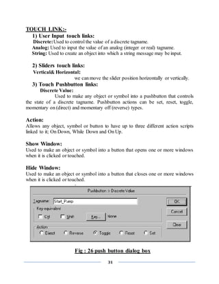
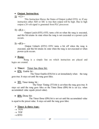
![16
contacts which pass on from left to right the condition "ON" or "OFF" which
correspond to the Boolean values TRUE and FALSE. To each contact belongs a
Boolean variable. If this variable is TRUE, then the condition is passed from left to
right along the connecting line. Otherwise the right connection receives the value
OFF.
INPUT represented by (I)
OUTPUT represented by (O)
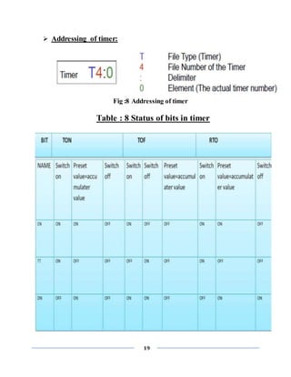
Addressing method:
1 slot=32 bit=2 word (1 char. / word=2 byte=16 bit)
Input addressing:
File letter: Slot number. Word number/Bit number
Forexample:- I:2.1/1
Output addressing:
File letter: Slot number. Word number/Bit number
Forexample:- O:2.1/1
GENERALLY USED INSTRUCTIONS & SYMBOL FOR
PLC PROGRAMMING:-
Input Instruction:
1) --[ ]—
This Instruction is Called XIC or Examine If Closed. ie; If a NO
switch is actuated then only this instruction will be true. If a NC switch is
actuated then this instruction will not be true and hence output will not be
generated.
2) --[]—
This Instruction is Called XIO or Examine If Open ie; If a
NC switch is actuated then only this instruction will be true. If a NC
switch is actuated then this instruction will not be true and hence output
will not be generated.](https://image.slidesharecdn.com/finalrepotofsummerinternship-201001035954/85/summer-internship-report-on-PLC-SCADA-16-320.jpg)
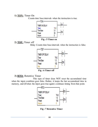
![21
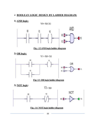
2) CTD: Count Down
Decrements the accumulate value at each false-to true
transition and retains the accumulated value when the instruction goes false or
when power cycle occurs.
Fig: 10 Count Down
Addressing of counter:
Fig: 11 Addressing of timer
RESET: --(RES)--
Reset the accumulated value and status bits of a timer or counter.
A C5:0
-------[ ]---------------------(RES)--------------------------
When A is true than counter C5:0 is reset.](https://image.slidesharecdn.com/finalrepotofsummerinternship-201001035954/85/summer-internship-report-on-PLC-SCADA-21-320.jpg)
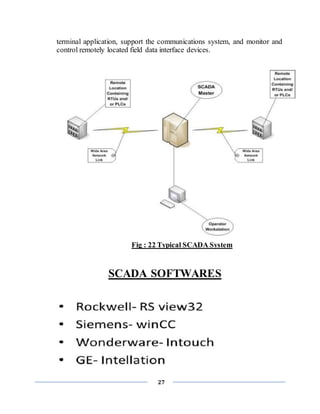
![26
SCADA
(SUPERVISORY CONTROL AND DATA ACQUISITION)
INTRODUCTION
SCADA stands for Supervisory Control And Data Acquisition. As the name
indicates, it is not a full control system, but rather focuses on the supervisory level.
As such, it is a purely software package that is positioned on top of hardware to
which it is interfaced, in general via Programmable Logic Controllers (PLCs), or
other commercial hardware modules.
SCADA systems are used to monitor and
control a plant or equipment in industries such as telecommunications, water and
waste control, energy, oil and gas refining and transportation. These systems
encompass the transfer of data between a SCADA central host computer and a
number of Remote Terminal Units (RTUs) and/or Programmable Logic Controllers
(PLCs), and the central host and the operator terminals. A SCADA system gathers
information (such as where a leak on a pipeline has occurred), transfers the
information back to a central site, then alerts the home station that a leak has
occurred, carrying out necessary analysis and control, such as determining if the
leak is critical, and displaying the information in a logical and organized fashion.
SCADA systems consistof:
1) One or more field data interface devices, usually RTUs, or PLCs, which
interface to field sensing devices and local control switchboxes and valve
actuators.
2) A communications system used to transfer data between field data interface
devices and control units and the computers in the SCADA central host. The
system can be radio, telephone, cable, satellite, etc., or any combination of
these.
3) A central host computer server or servers (sometimes called a SCADA
Center, master station, or Master Terminal Unit (MTU).
4) A collection of standard and/or custom software [sometimes called Human
Machine Interface (HMI) software or Man Machine Interface (MMI)
software] systems used to provide the SCADA central host and operator](https://image.slidesharecdn.com/finalrepotofsummerinternship-201001035954/85/summer-internship-report-on-PLC-SCADA-26-320.jpg)