Download as PDF, PPTX


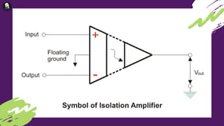


The document provides an overview of biomedical bio-amplifiers, which are electronic devices that amplify low-amplitude physiological signals for accurate monitoring. It discusses various types of bio-amplifiers, including differential, operational, instrumentation, chopper, and isolation amplifiers, highlighting their roles in maintaining signal integrity and protecting patients from electrical shocks. Key requirements for these amplifiers include high input impedance and specific configurations to prevent distortion and enhance signal quality in biomedical applications.


