Downloaded 301 times
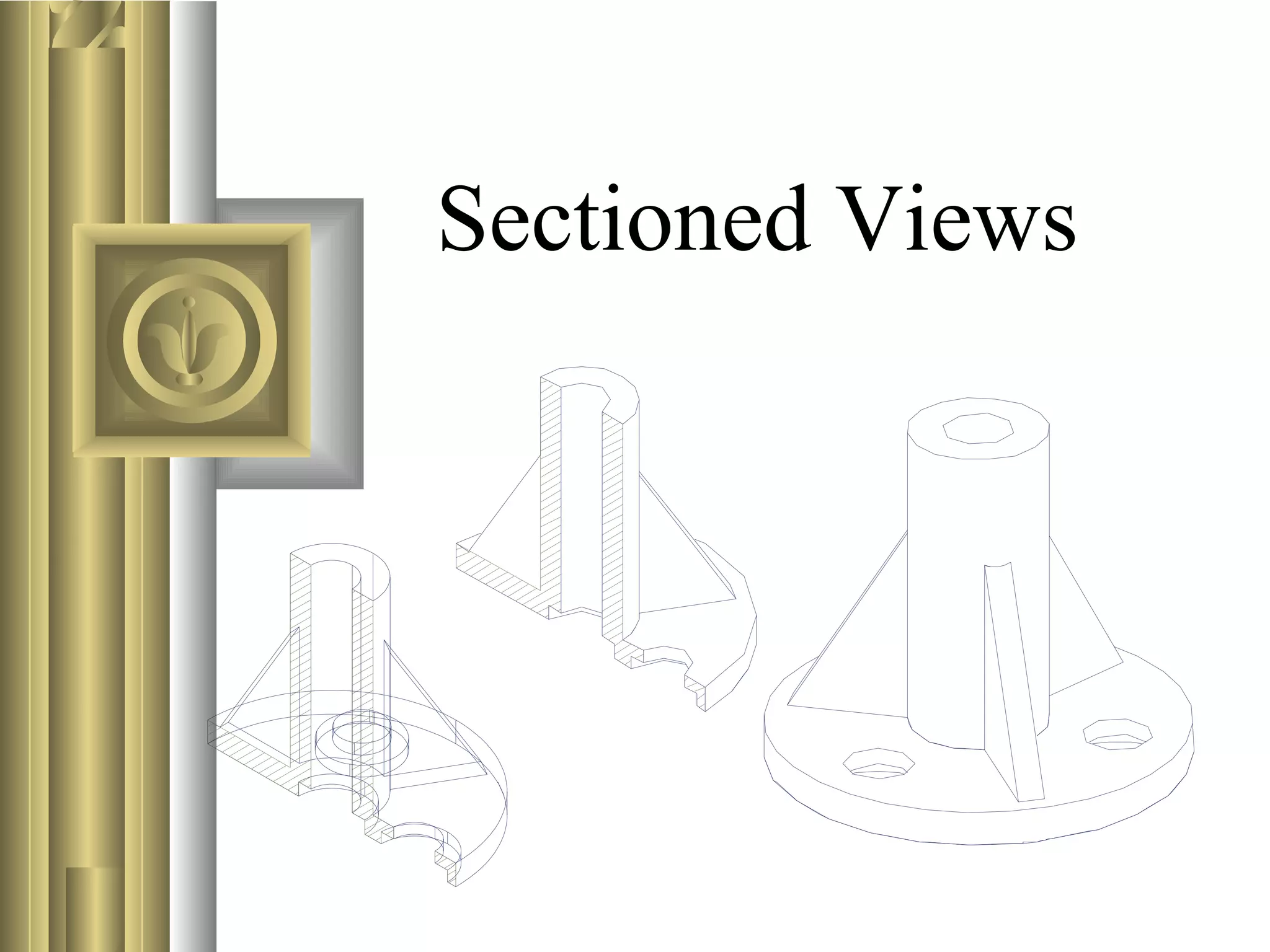
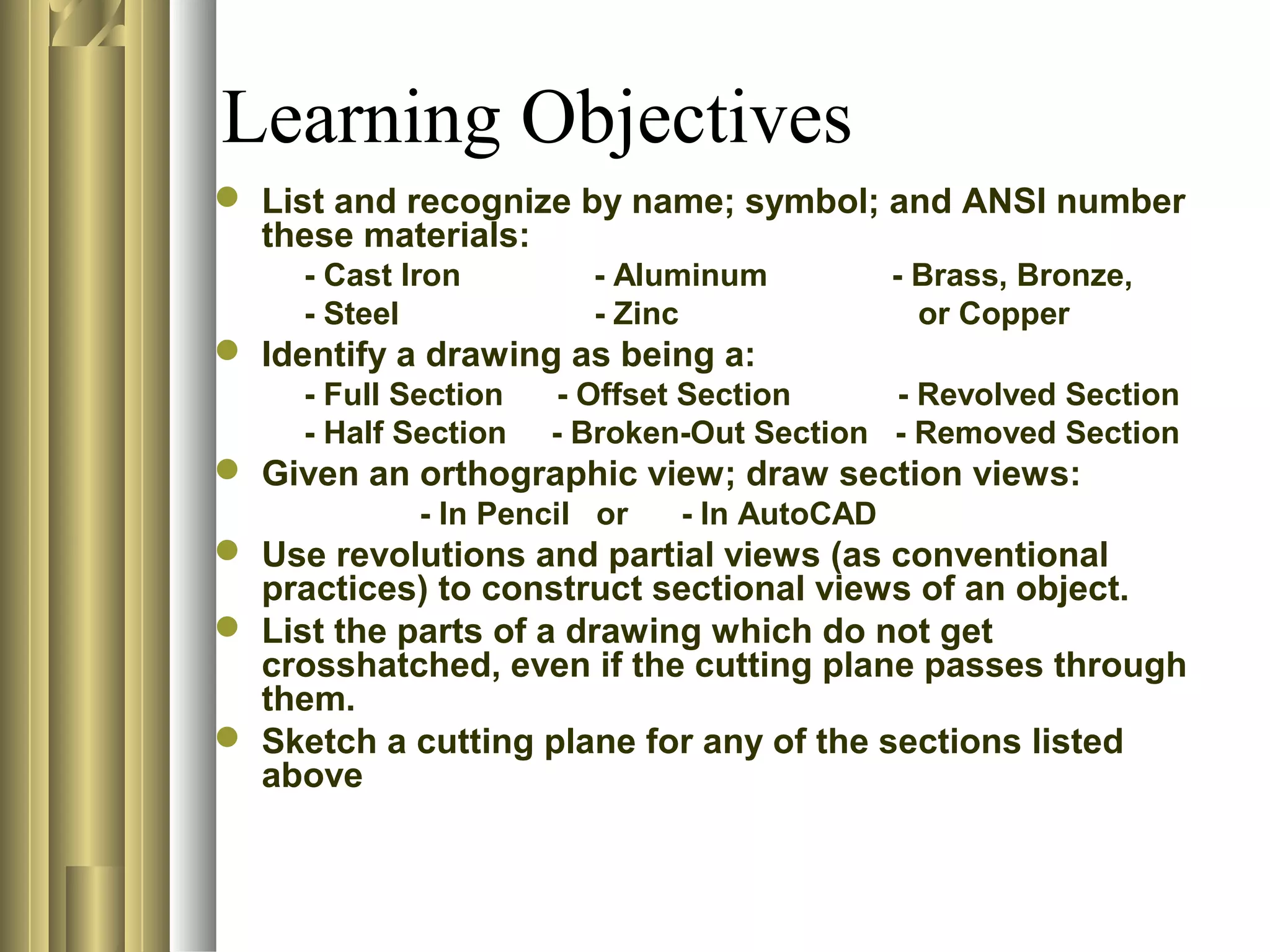
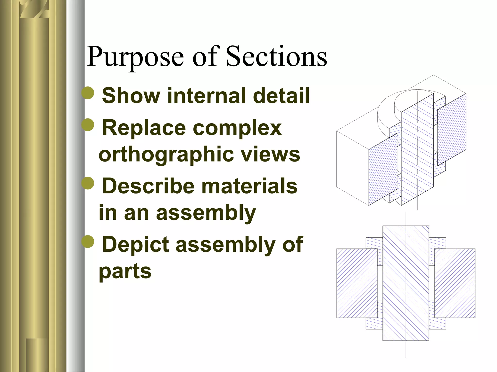
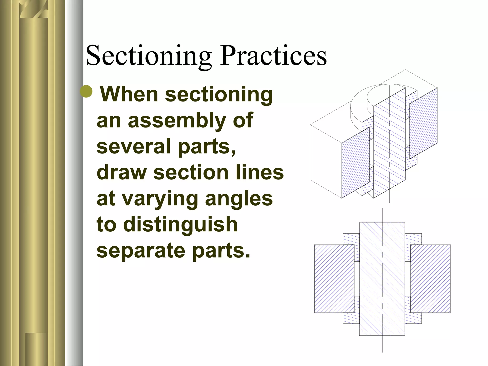
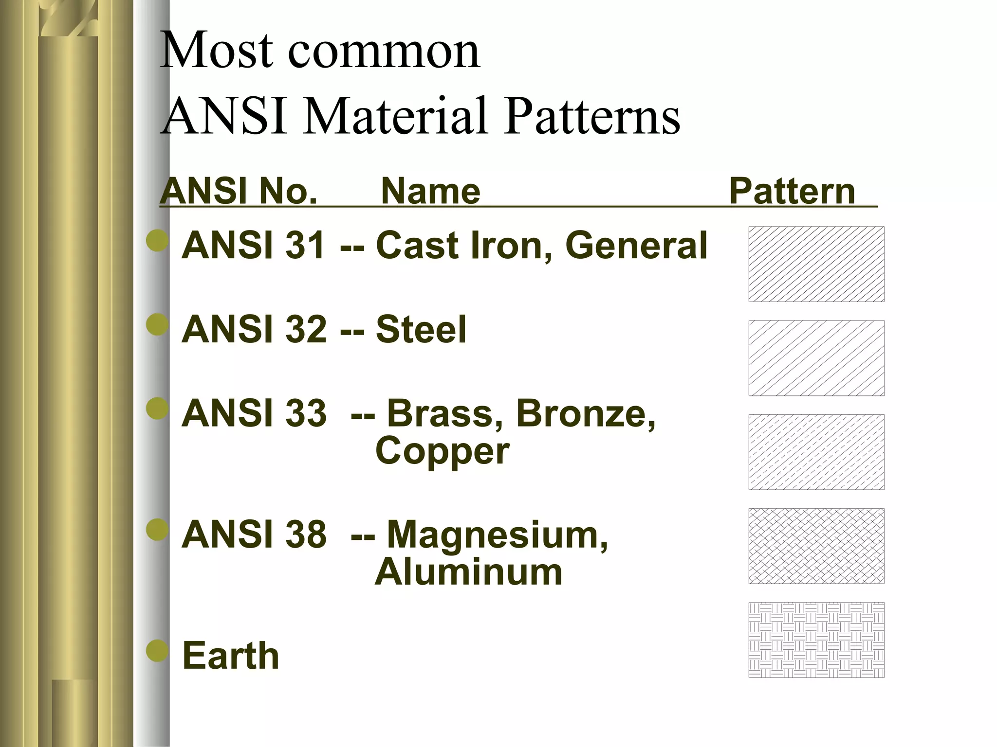
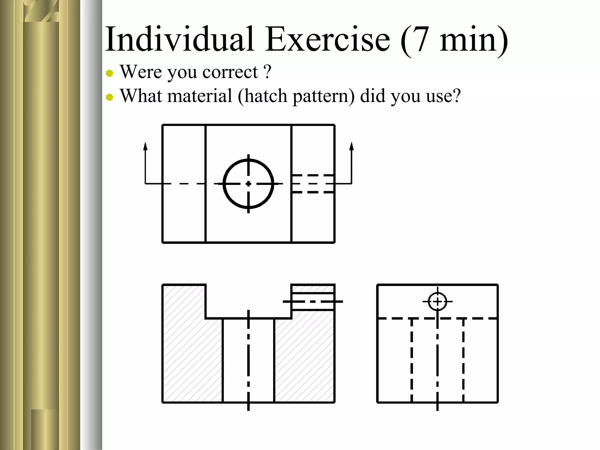
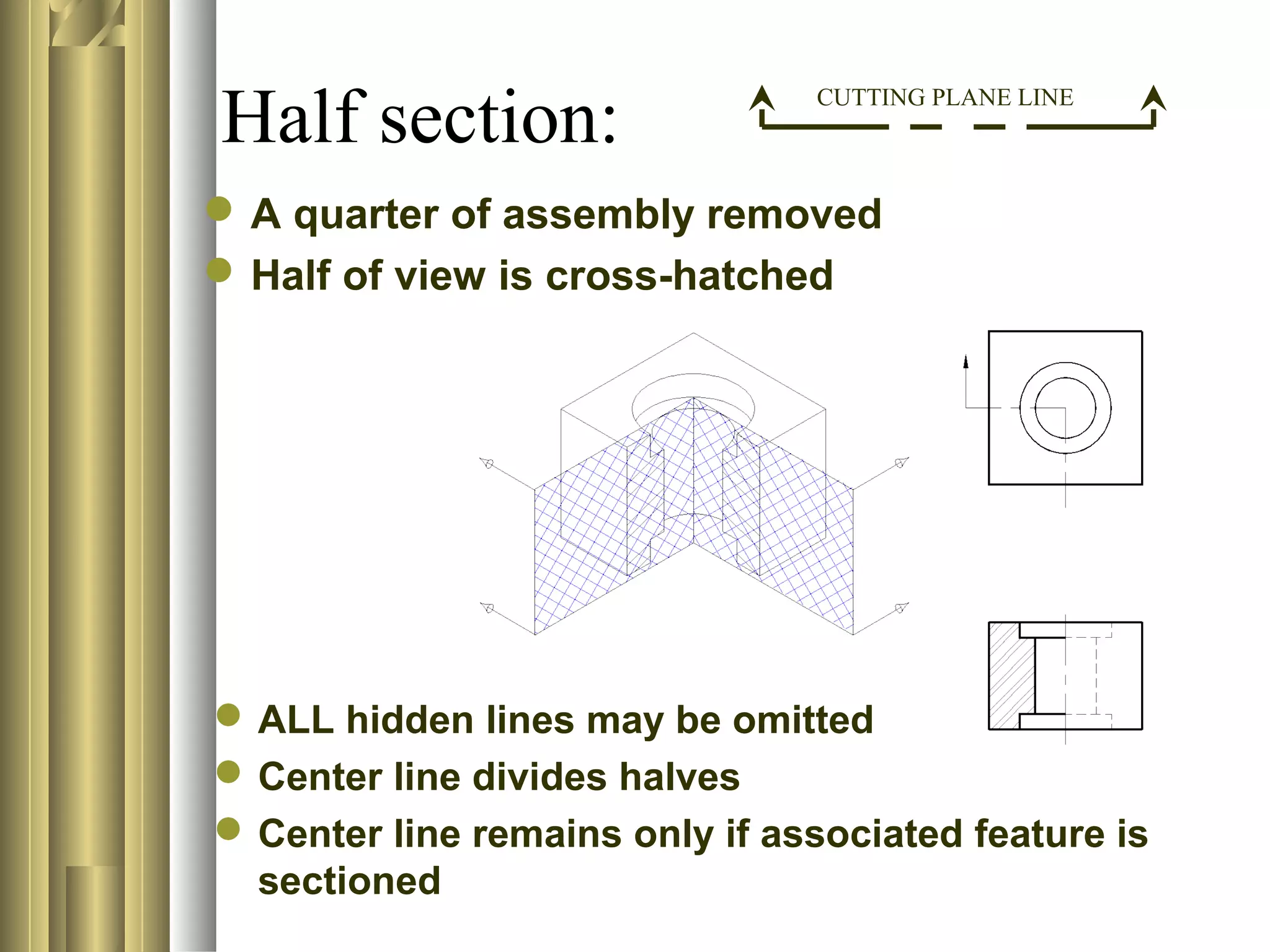
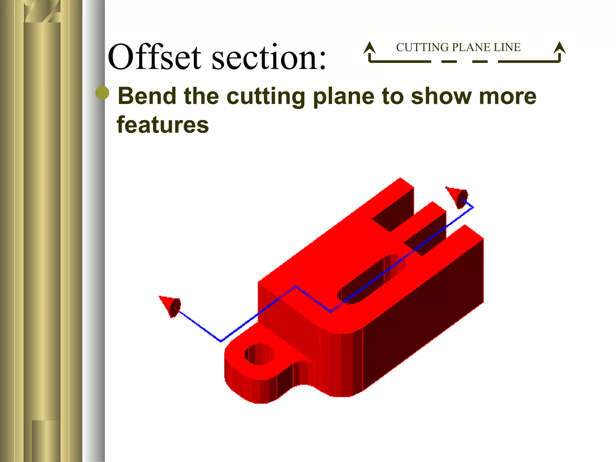
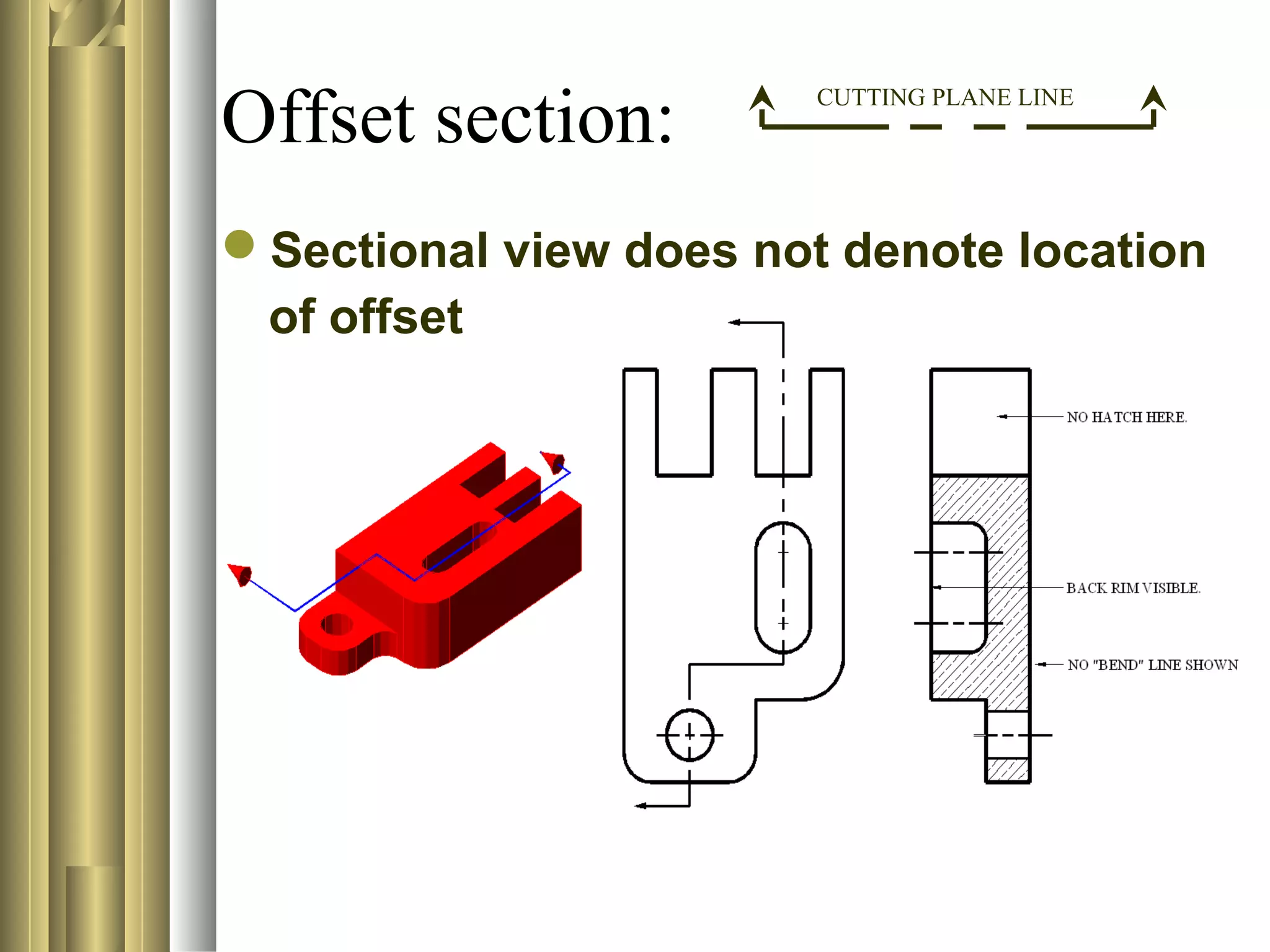

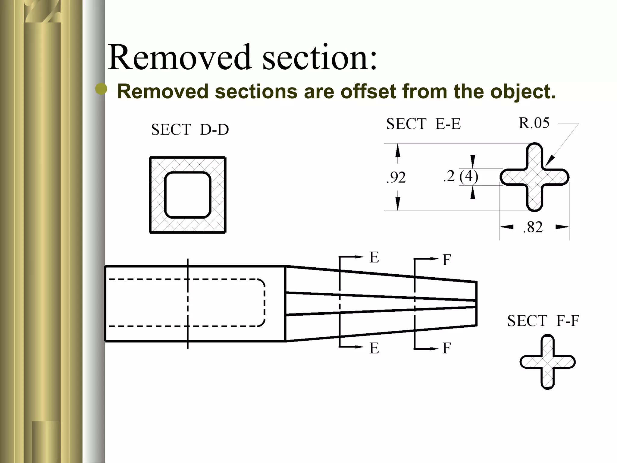
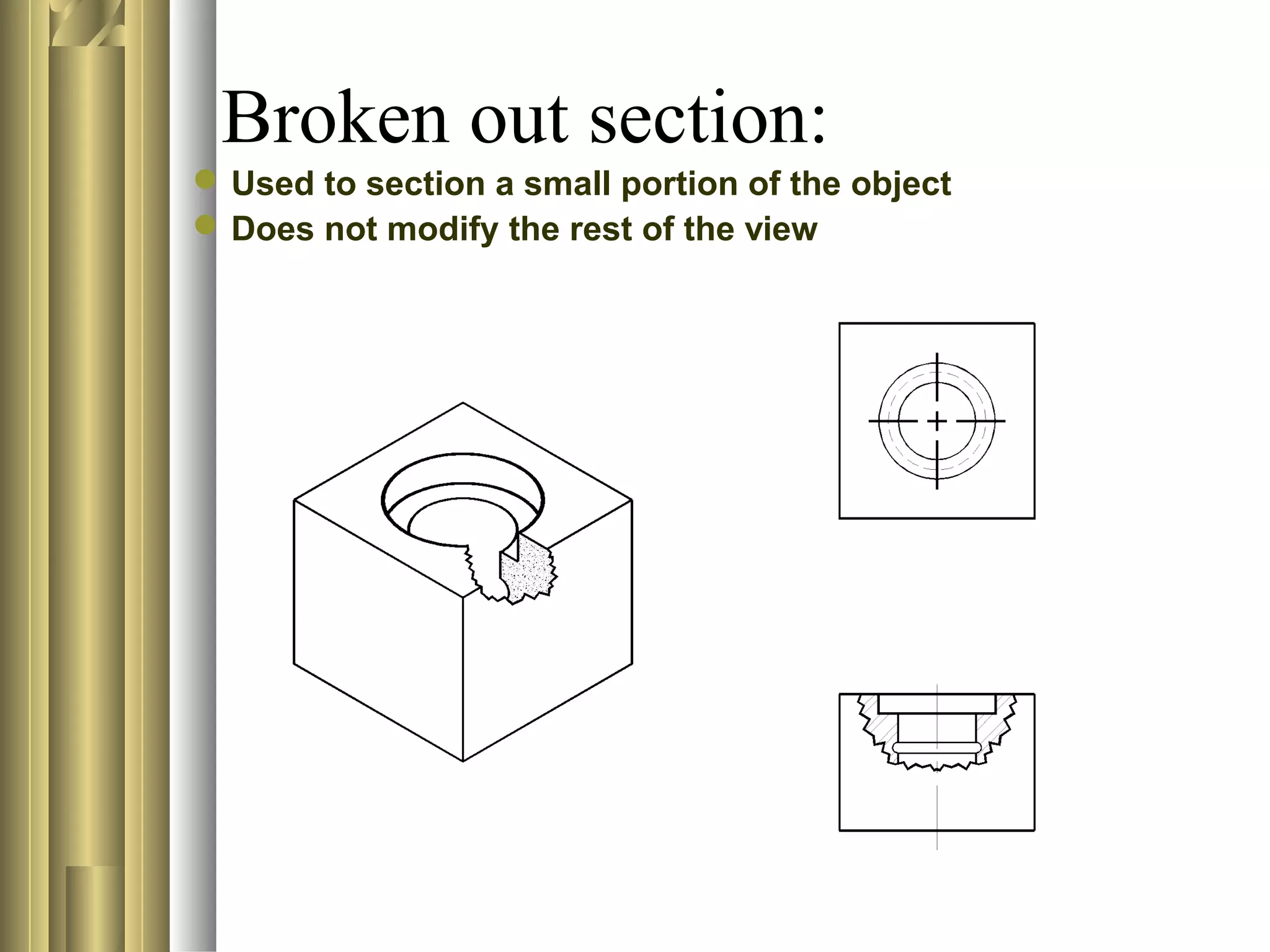

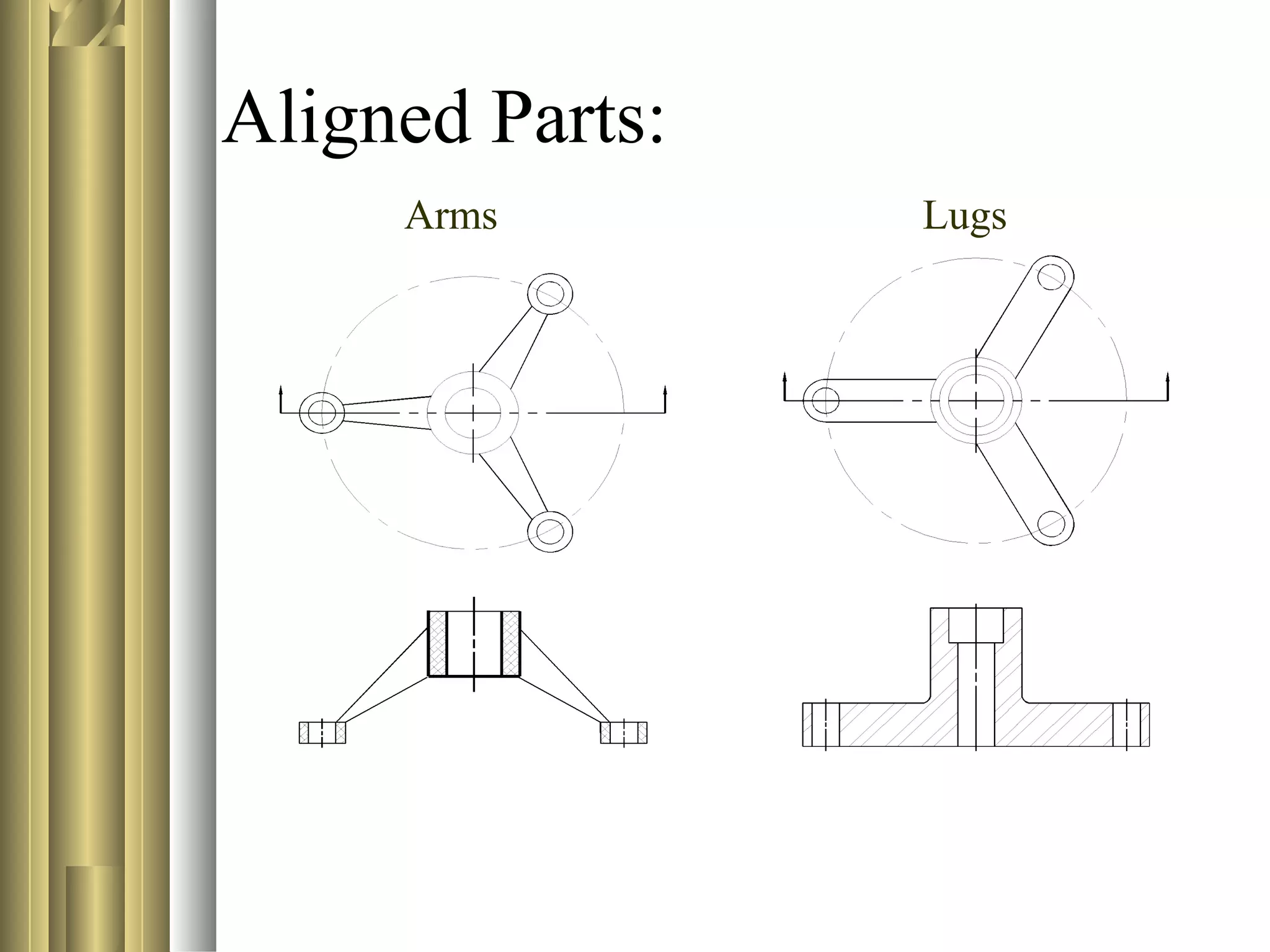

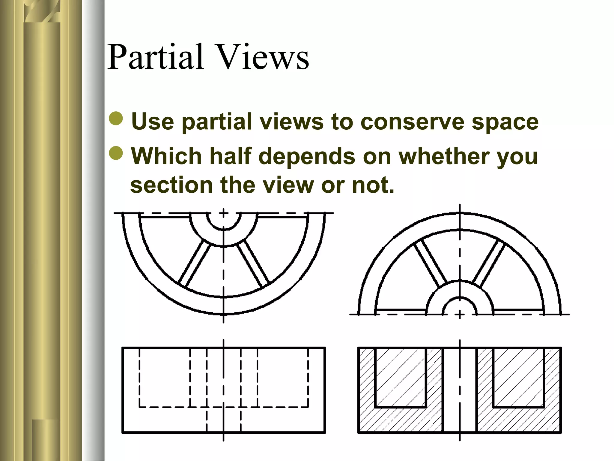

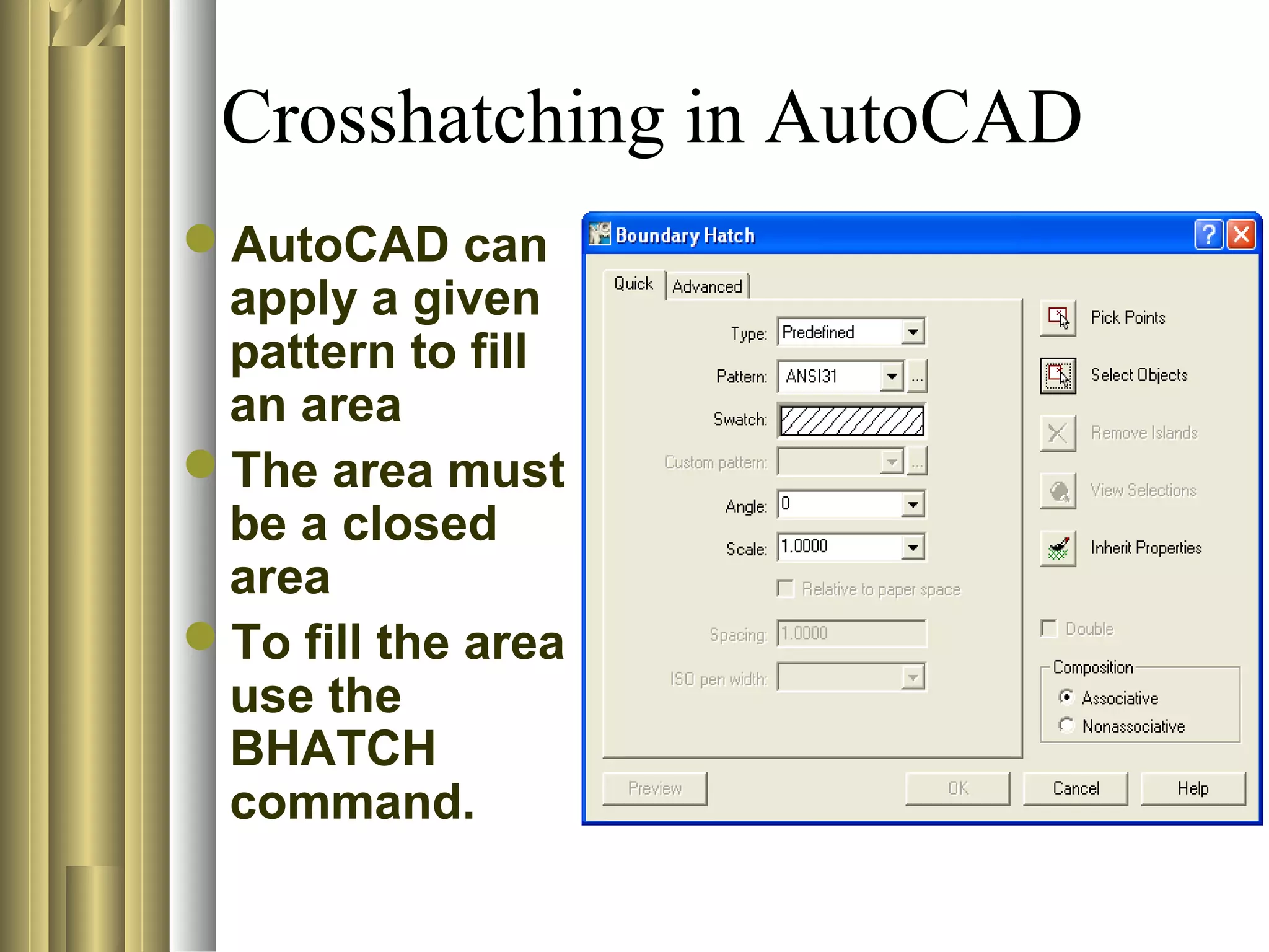


This document discusses section views and sectioning practices in technical drawings. It covers the following key points: - The purpose of section views is to show internal details of an object, replace complex orthographic views, describe materials in an assembly, and depict the assembly of parts. - Common sectioning practices include using different cutting plane angles for separate parts, standard hatch spacing and line thicknesses, and not drawing section or hatch lines parallel to boundaries. - Sectional view types include full sections, half sections, offset sections, revolved sections, removed sections, and broken out sections. - Not all features get crosshatched, even if the cutting plane passes through, such as ribs, webs