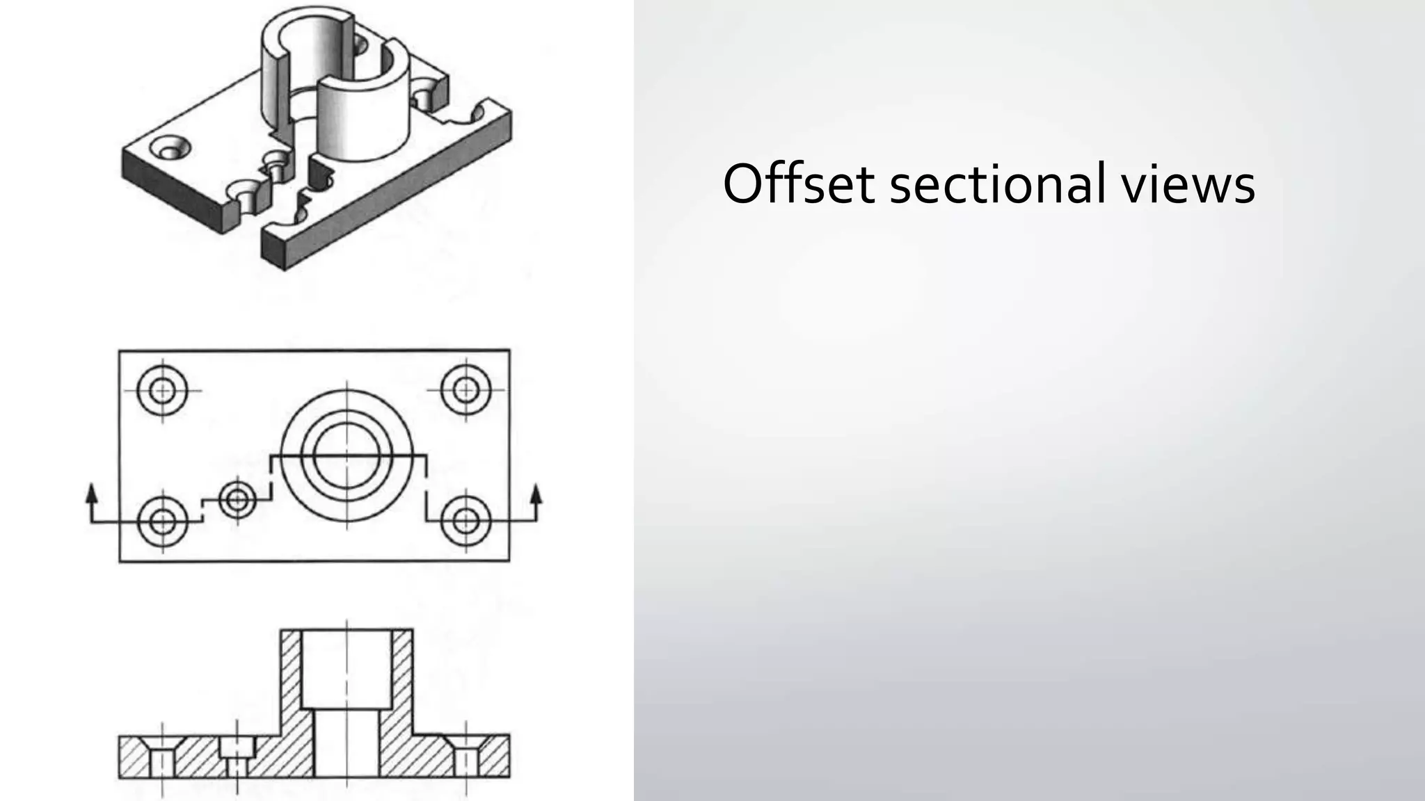
Sectional Standards and
Conventions
Answers
A 35 mm
B 46 mm
C 32 mm
D 11 mm
E 15 mm
H 49 mm
J 11 mm
SectionalViews
• The main purpose of a sectional view is to effectively communicate internal
information to enhance the viewer’s understanding of the part.
• There are several different types of section views that engineers use to
communicate internal geometry.
• Full sectional view
• Half sectional view
• Offset sectional view
Hidden Detail
• Sometimes an object features detail that are internal and cannot be
seen by viewing external surfaces.
• In these circumstances, orthographic drawing is vital in depicting
otherwise hidden detail.
• Hidden detail may appear on any of the featured views.
Hidden Detail
• Hidden details are indicted by a thin broken line. It is essential
that this line convention be followed so that the detail is clearly
understood and not mistaken for an outline.
Cross-sections
• The cross-sectioning of an object allows for the internal details to be clearly
shown.
• A cross-section is literally a ‘cut-through’ view of an object.
Cross-sections
An imaginary cut is
made at an appropriate
point to display the
relevant information.
The cutting plane
• The path of the imaginary cut is indicated on the orthographical drawing by
a cutting plane.
• The cutting plane is shown as a broken line with thick lines at each end.
• Narrow arrowheads touch the end of the cutting plane, indicating the
direction of the cut and the subsequent direction of view.
The cutting plane
The first cross-section is always
labelled Section A-A, subsequent
sections are B-B, C-C and so on.
Crosshatching
• In order to show solid areas of
the object that have been ‘cut’,
hatching is used
• The hatching should be drawn
at 45° and be suitably spaced
relative to the area covered.
Crosshatching
• Where adjacent parts of an object meet, the direction of hatching should be
reversed.
Full sectional view
• A full section view is created by running the cutting plane through the entire
length of the object being sectioned
• The cutting plane may be identified and indicated in the usual manner to
increase clarity.
Half sectional views
• A symmetrical object or assembly may be drawn as a half section, showing
one half up to the centre line in section and the other half in full view
• The cutting plane effectively removes a quarter of the object
• A normal centreline is listed on the section view.The wording, half section,
can be confusing because one thinks of showing half the part.
• Remember, a half section shows one-fourth of the part, not one half!
Half sectional views
Offset sectional view
• In order to include features that are not in a straight line, the cutting-plane
line may be offset or bent, so as to include several planes or curved surfaces
• An offset section is similar to a full section in that the cutting plane extends
through the object from one side to the other.
• The change in direction of the cutting-plane line is not shown on the
sectional view.
Offset sectional views
Rules to remember
• A sectional view shows the part of the component in front of the sectional
plane arrows
• Only the material which has been cut by the sectioning plane is cross-
hatched
• A sectional view must not have any full lines drawn over cross-hatched areas
• Dimensions are not inserted in cross-hatched sectioned areas

Sectional Standars and Conventions

  • 1.
  • 3.
    Answers A 35 mm B46 mm C 32 mm D 11 mm E 15 mm H 49 mm J 11 mm
  • 4.
    SectionalViews • The mainpurpose of a sectional view is to effectively communicate internal information to enhance the viewer’s understanding of the part. • There are several different types of section views that engineers use to communicate internal geometry. • Full sectional view • Half sectional view • Offset sectional view
  • 5.
    Hidden Detail • Sometimesan object features detail that are internal and cannot be seen by viewing external surfaces. • In these circumstances, orthographic drawing is vital in depicting otherwise hidden detail. • Hidden detail may appear on any of the featured views.
  • 6.
    Hidden Detail • Hiddendetails are indicted by a thin broken line. It is essential that this line convention be followed so that the detail is clearly understood and not mistaken for an outline.
  • 8.
    Cross-sections • The cross-sectioningof an object allows for the internal details to be clearly shown. • A cross-section is literally a ‘cut-through’ view of an object.
  • 9.
    Cross-sections An imaginary cutis made at an appropriate point to display the relevant information.
  • 10.
    The cutting plane •The path of the imaginary cut is indicated on the orthographical drawing by a cutting plane. • The cutting plane is shown as a broken line with thick lines at each end. • Narrow arrowheads touch the end of the cutting plane, indicating the direction of the cut and the subsequent direction of view.
  • 11.
    The cutting plane Thefirst cross-section is always labelled Section A-A, subsequent sections are B-B, C-C and so on.
  • 12.
    Crosshatching • In orderto show solid areas of the object that have been ‘cut’, hatching is used • The hatching should be drawn at 45° and be suitably spaced relative to the area covered.
  • 13.
    Crosshatching • Where adjacentparts of an object meet, the direction of hatching should be reversed.
  • 14.
    Full sectional view •A full section view is created by running the cutting plane through the entire length of the object being sectioned • The cutting plane may be identified and indicated in the usual manner to increase clarity.
  • 16.
    Half sectional views •A symmetrical object or assembly may be drawn as a half section, showing one half up to the centre line in section and the other half in full view • The cutting plane effectively removes a quarter of the object • A normal centreline is listed on the section view.The wording, half section, can be confusing because one thinks of showing half the part. • Remember, a half section shows one-fourth of the part, not one half!
  • 17.
  • 18.
    Offset sectional view •In order to include features that are not in a straight line, the cutting-plane line may be offset or bent, so as to include several planes or curved surfaces • An offset section is similar to a full section in that the cutting plane extends through the object from one side to the other. • The change in direction of the cutting-plane line is not shown on the sectional view.
  • 19.
  • 20.
    Rules to remember •A sectional view shows the part of the component in front of the sectional plane arrows • Only the material which has been cut by the sectioning plane is cross- hatched • A sectional view must not have any full lines drawn over cross-hatched areas • Dimensions are not inserted in cross-hatched sectioned areas