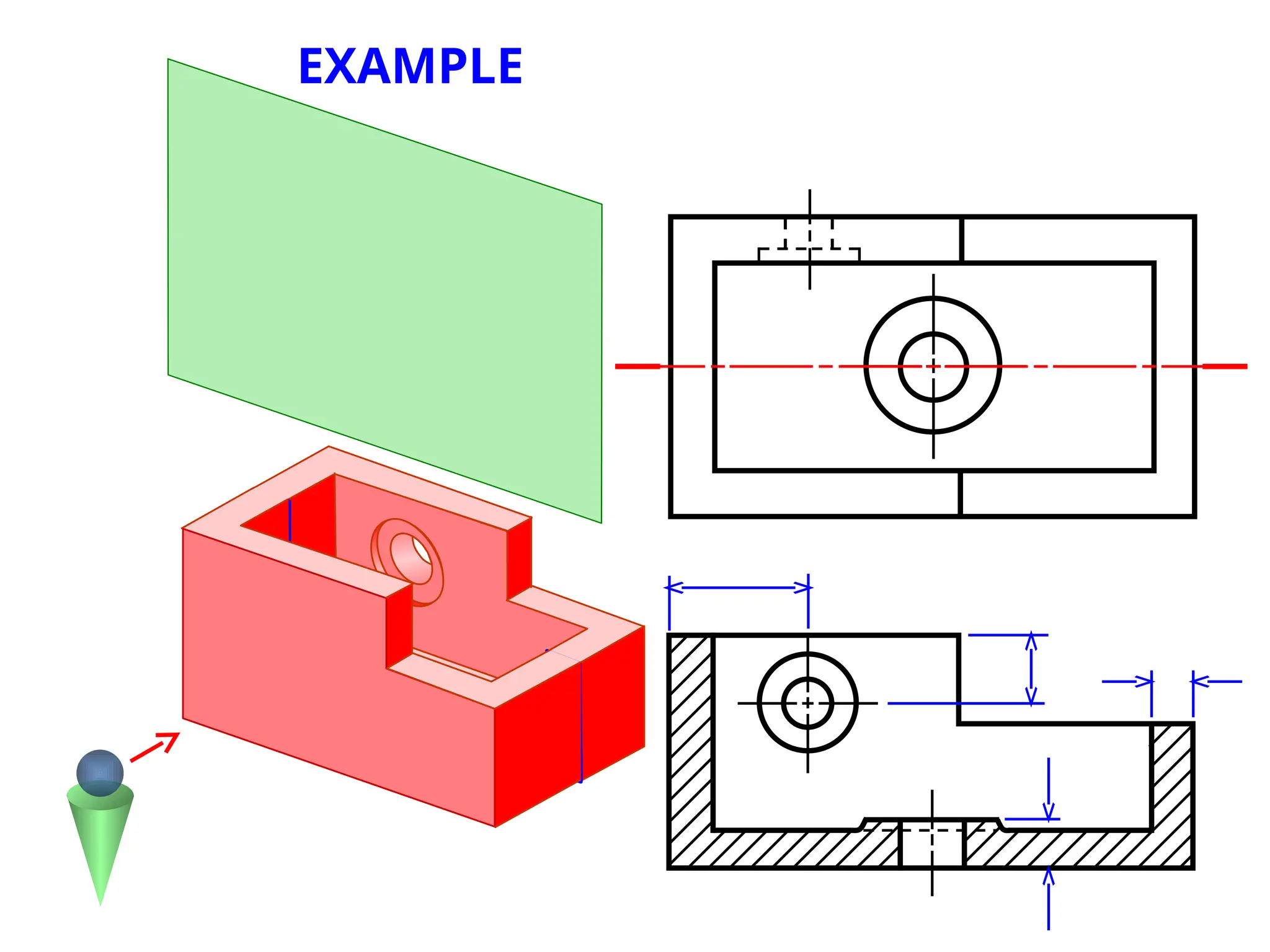
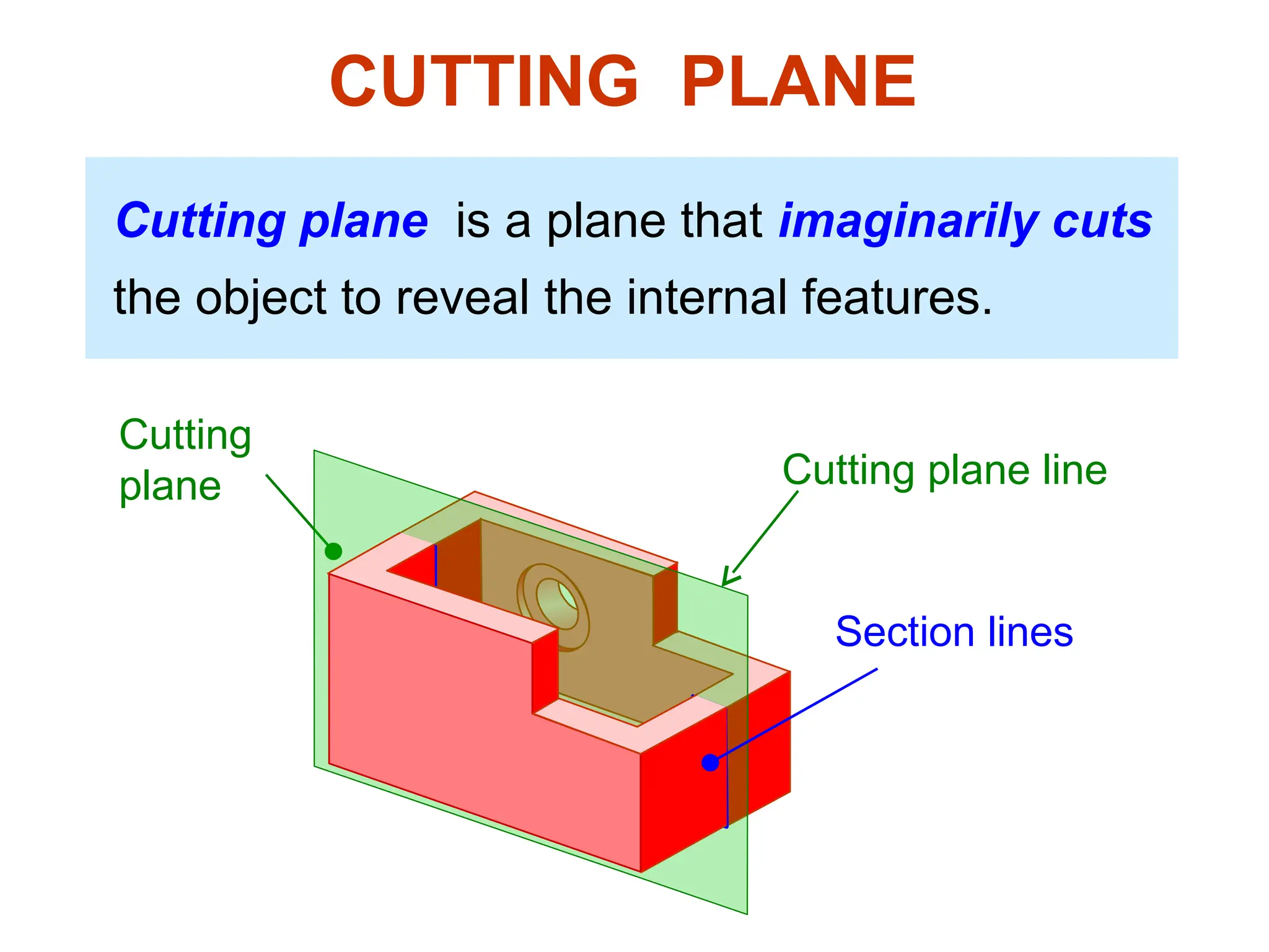
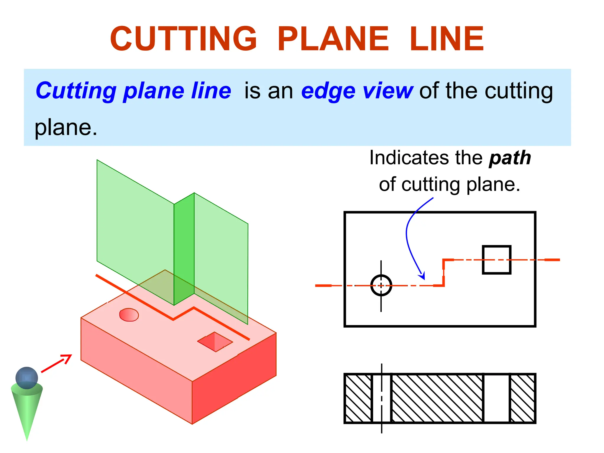
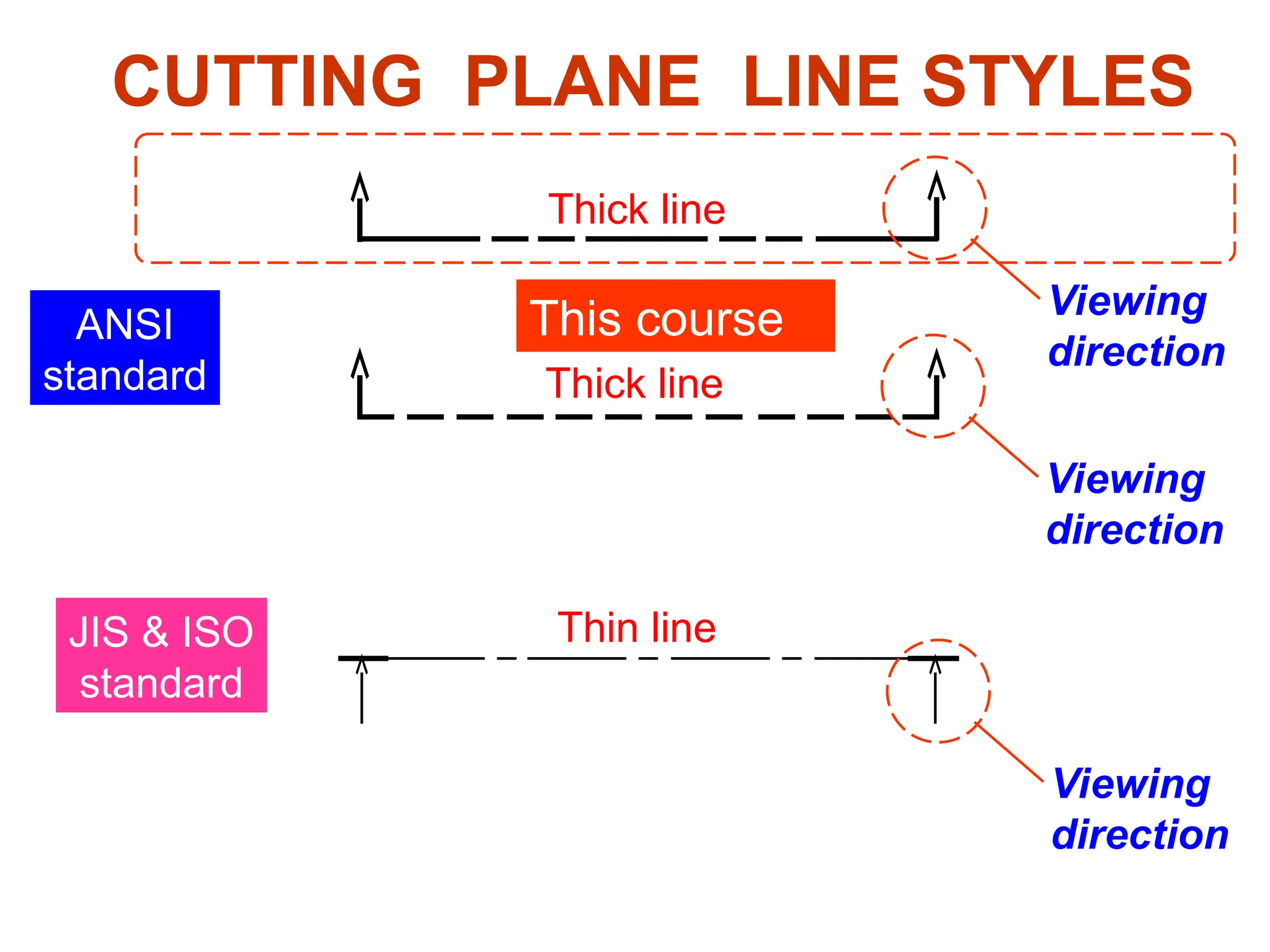
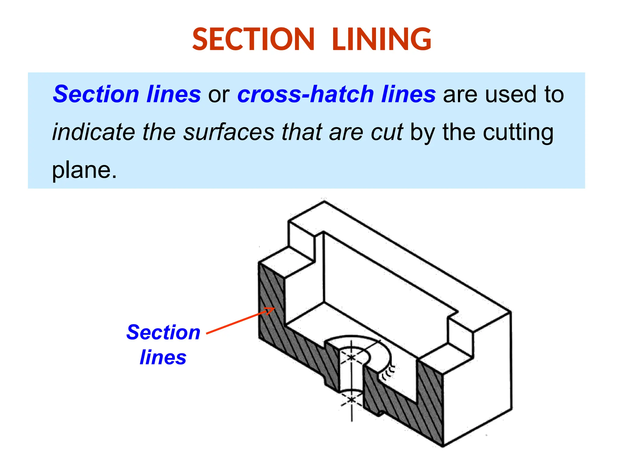
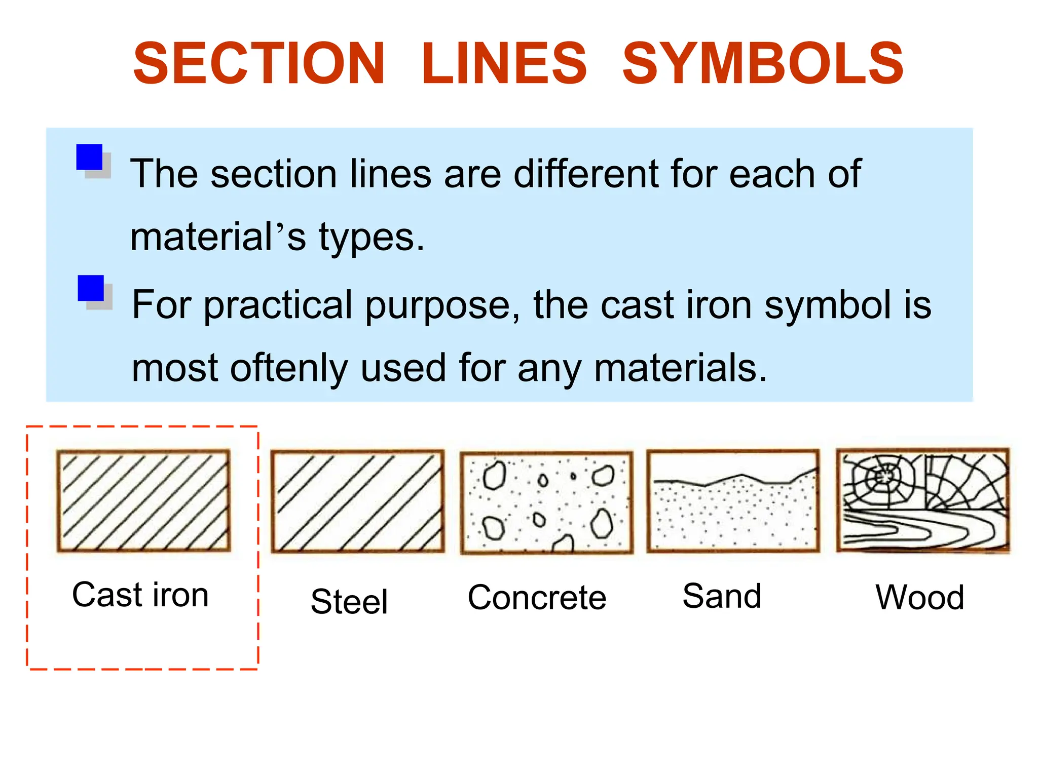
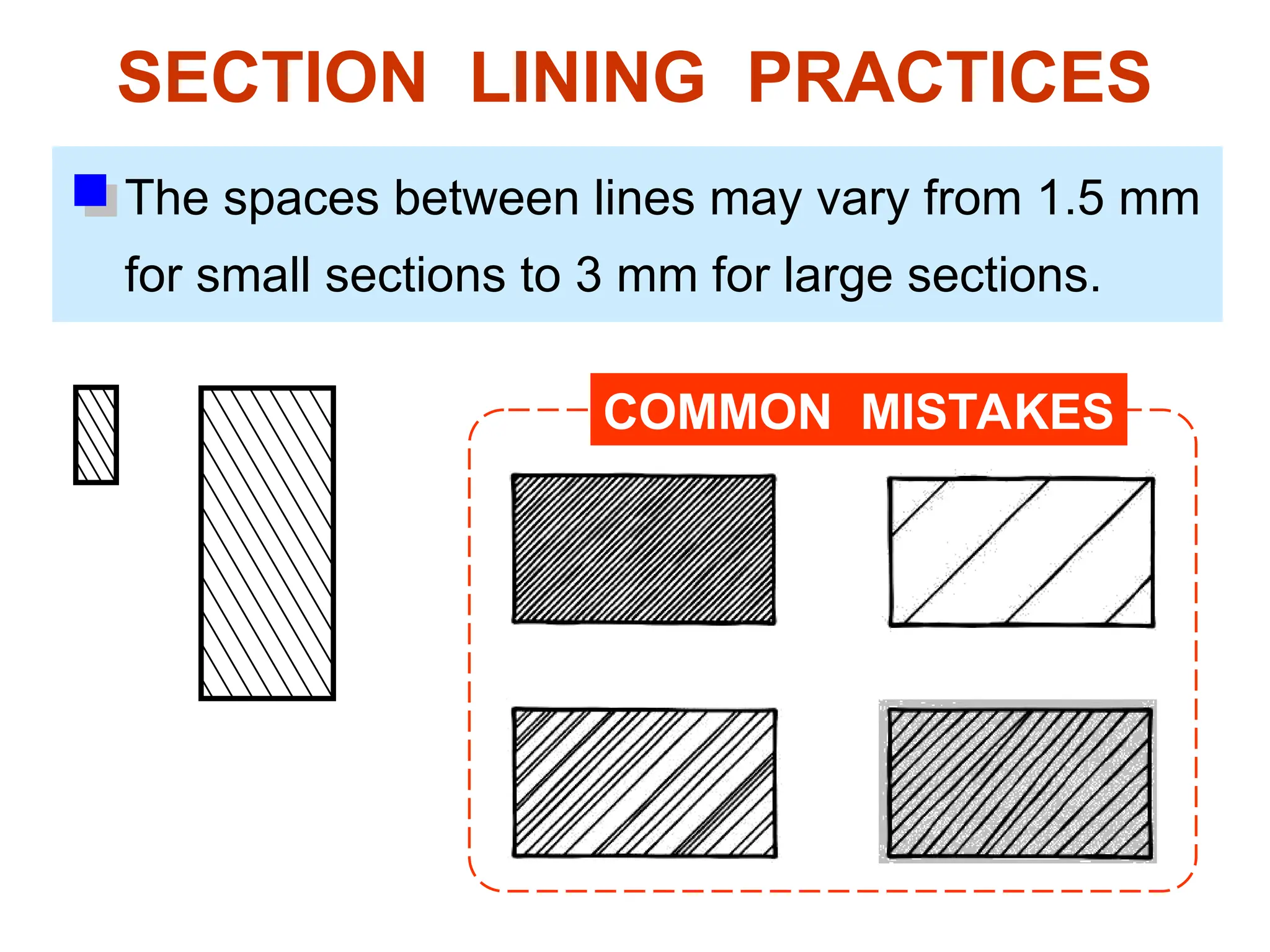
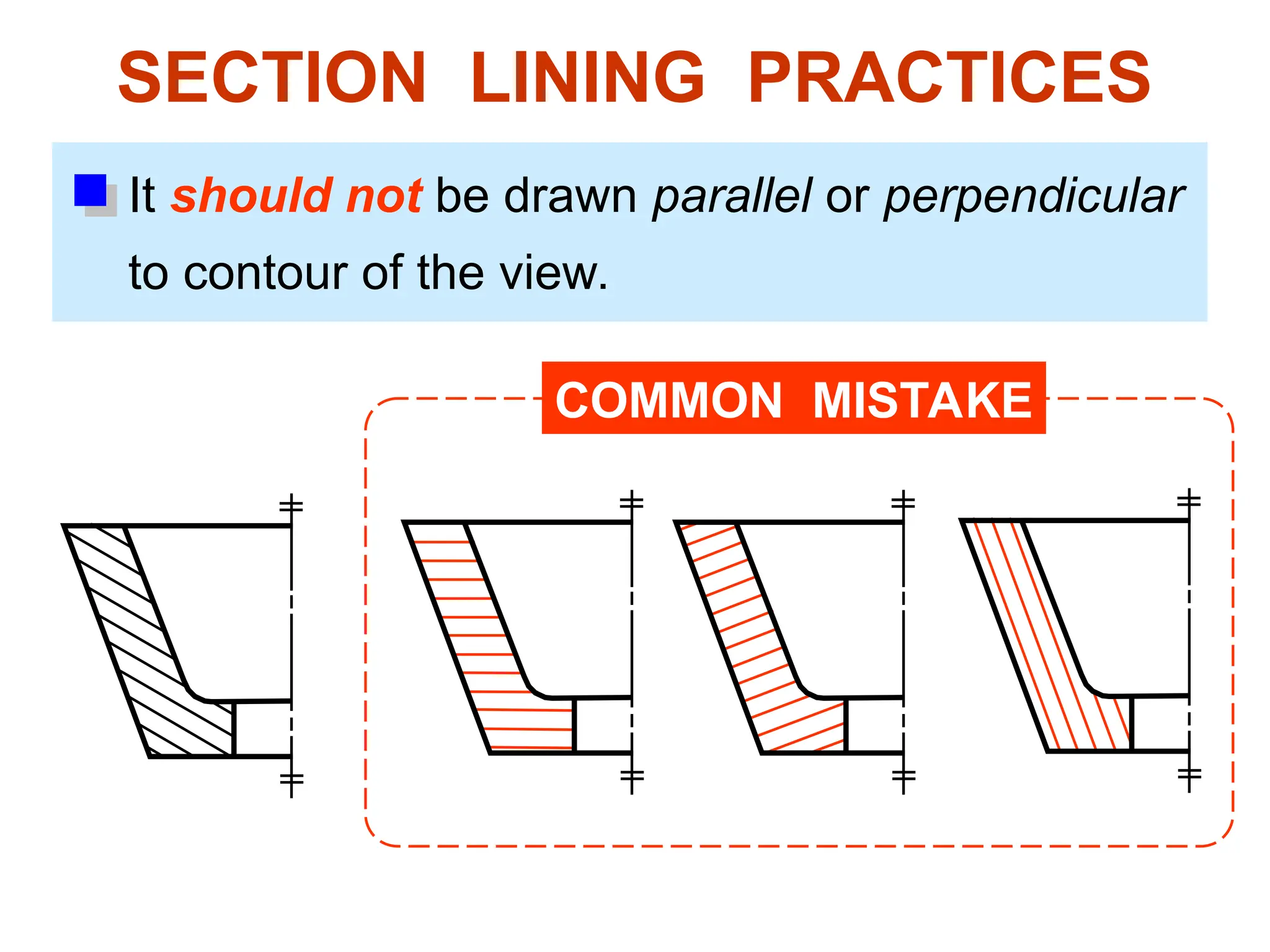
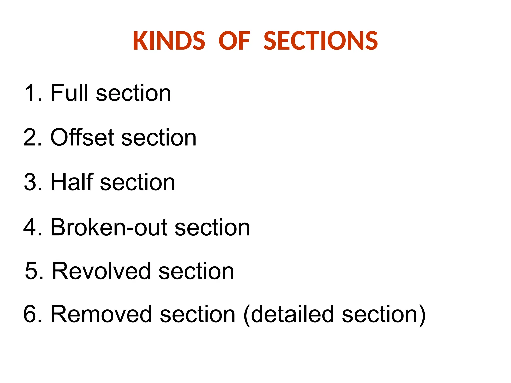
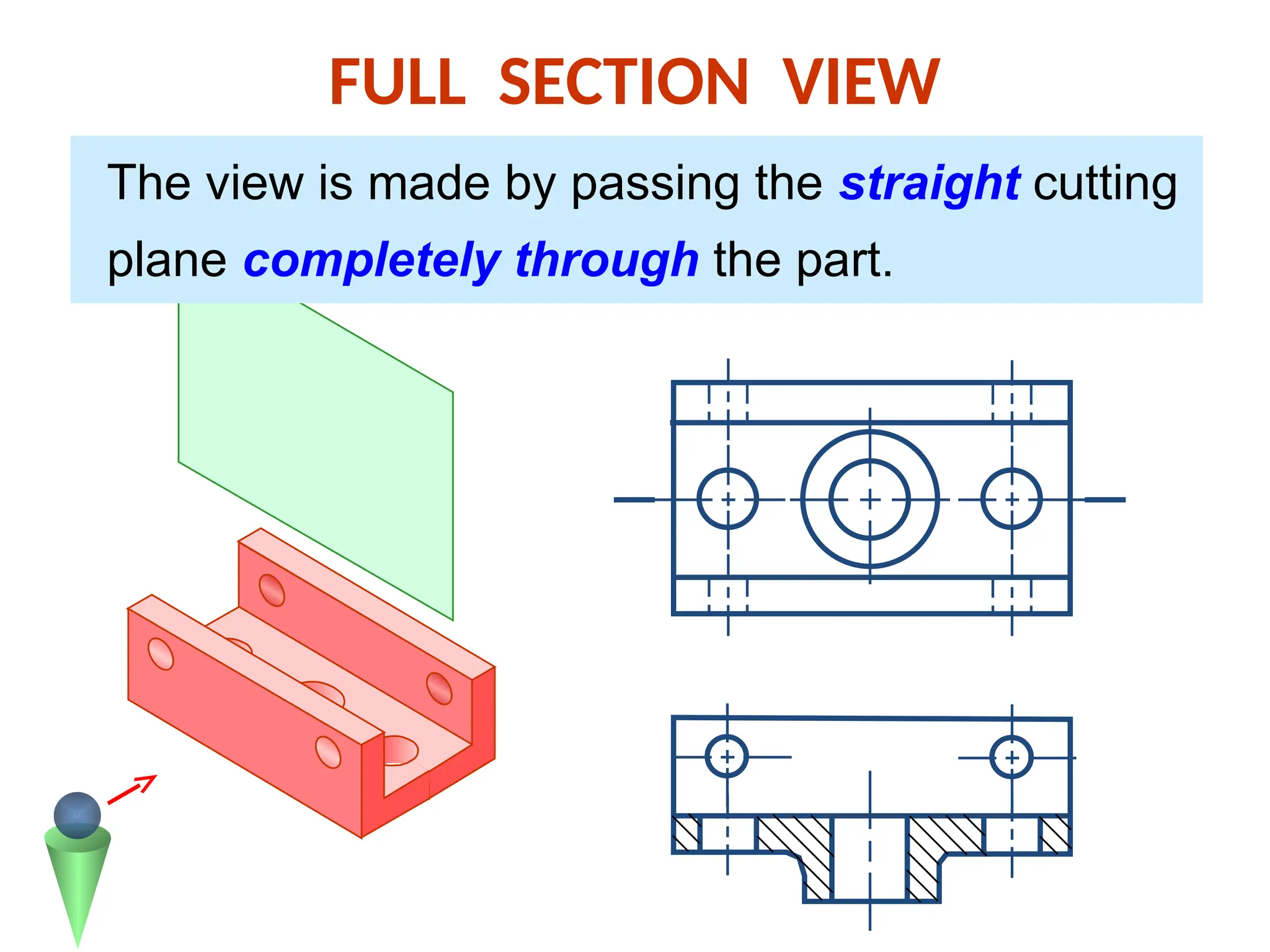
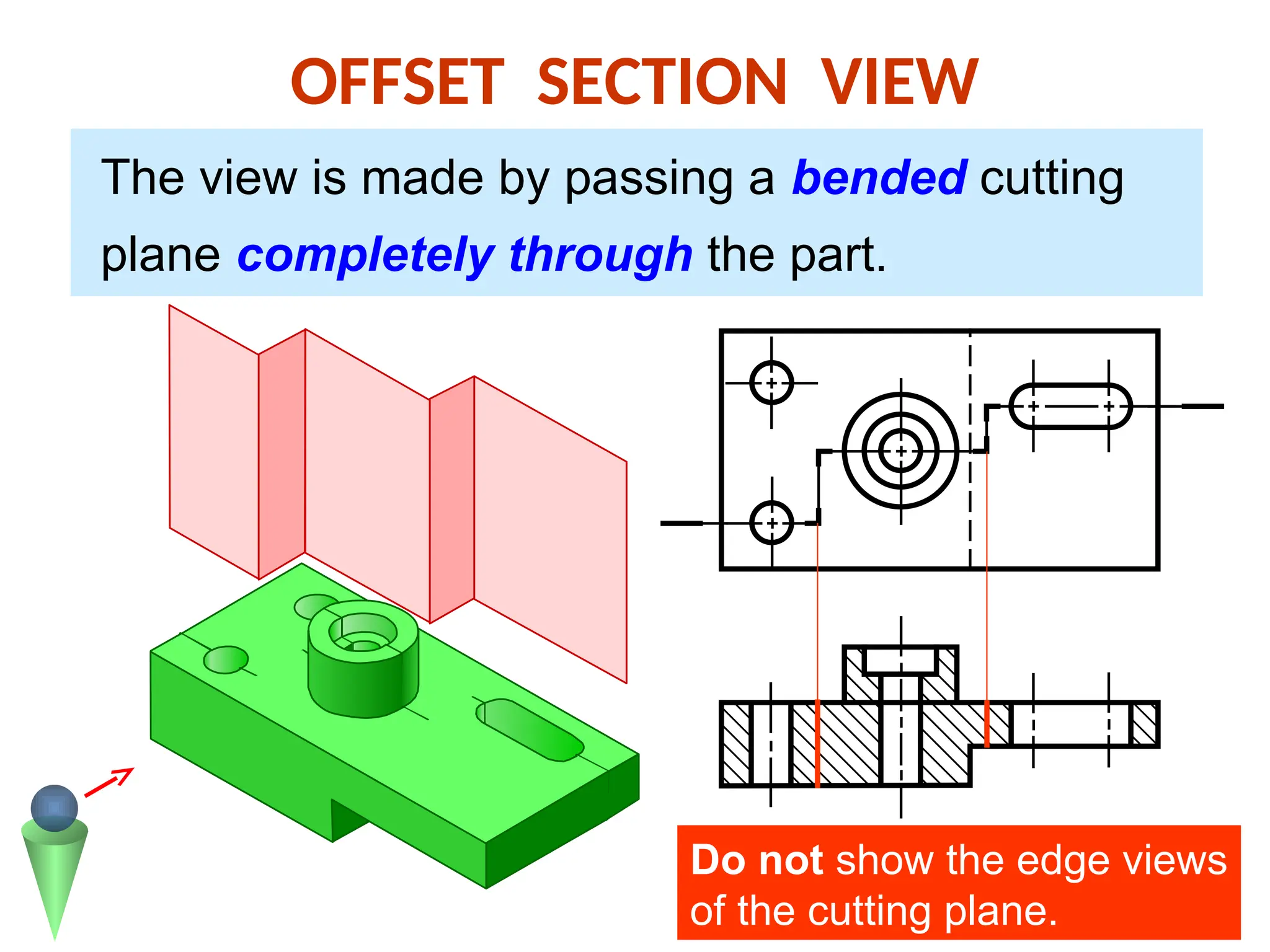
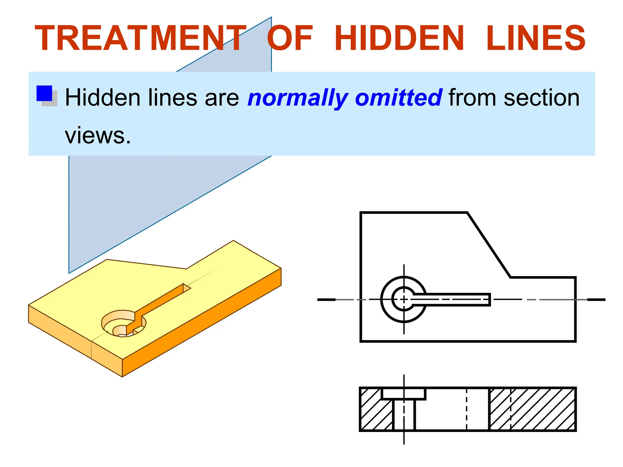
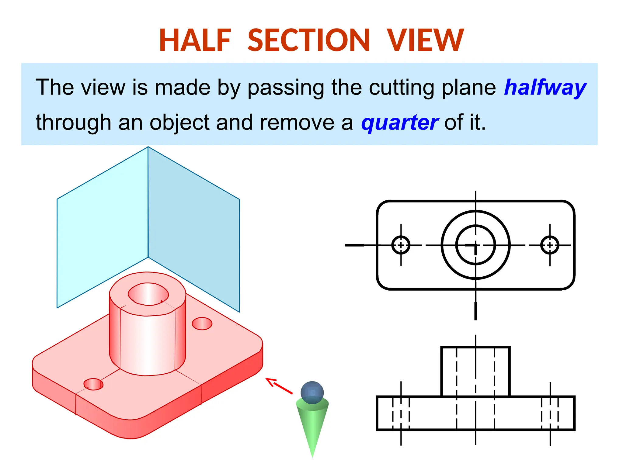
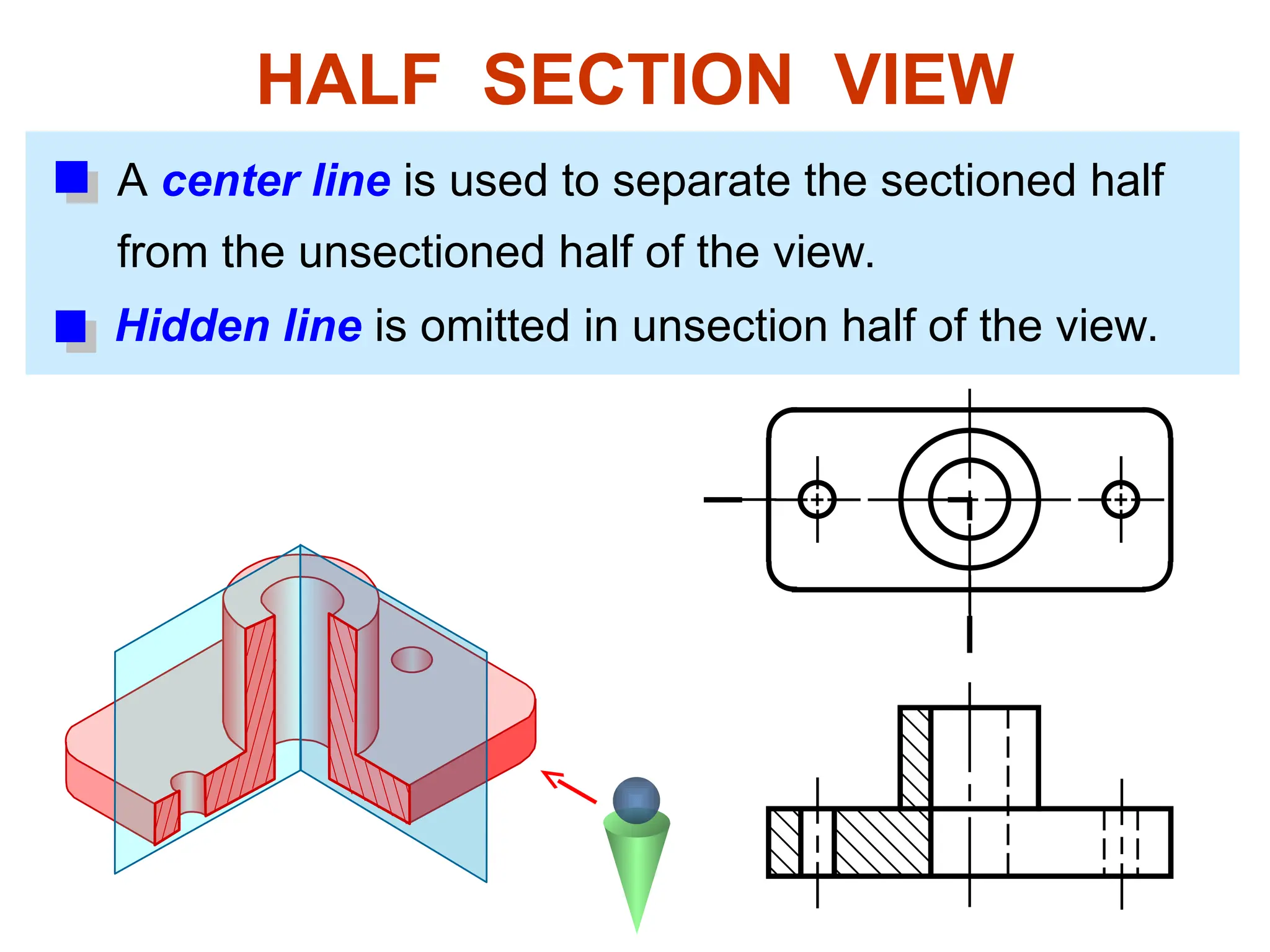
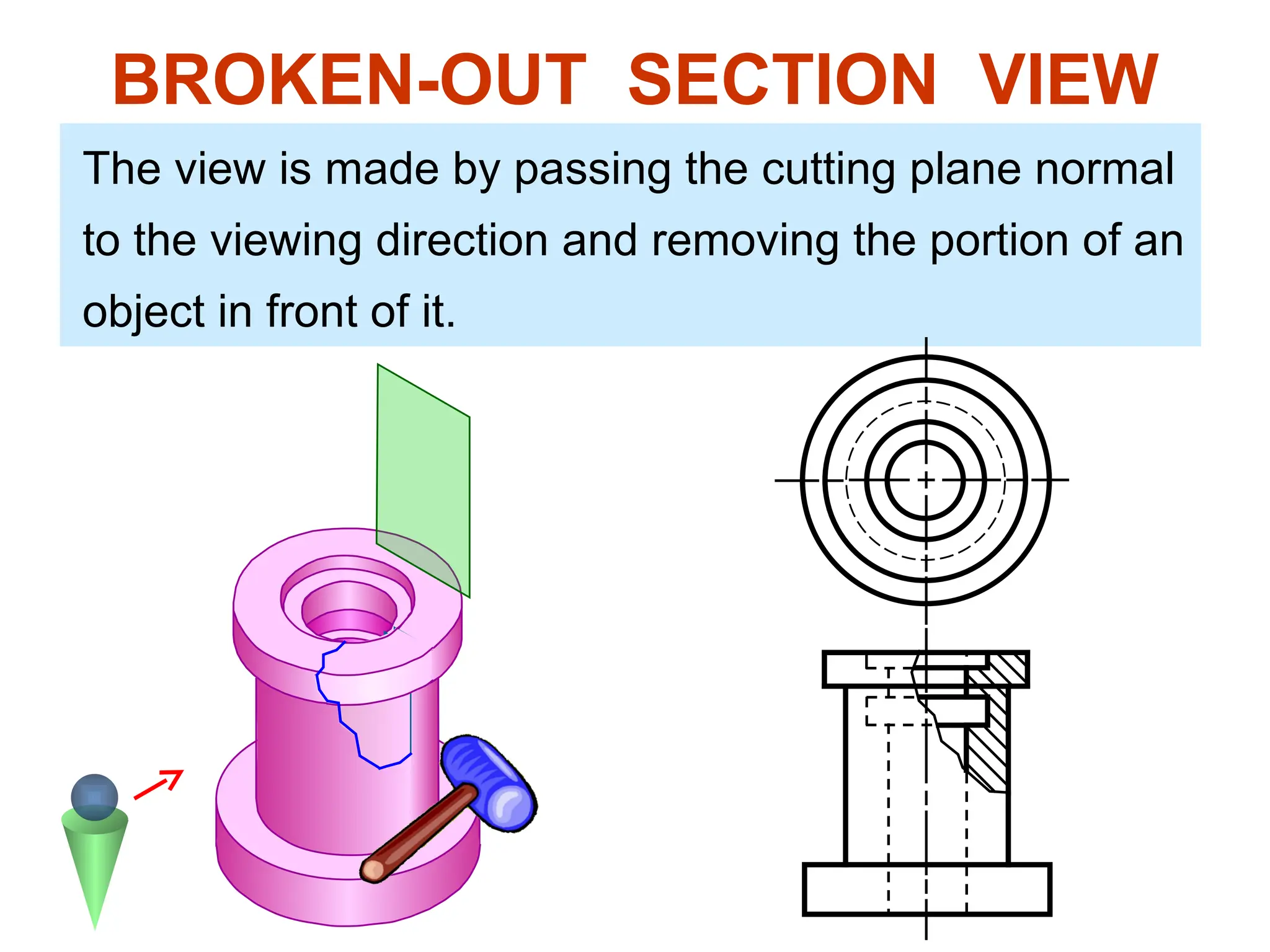
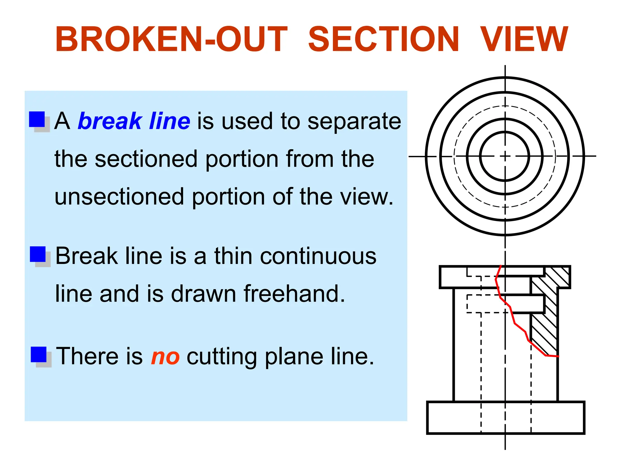
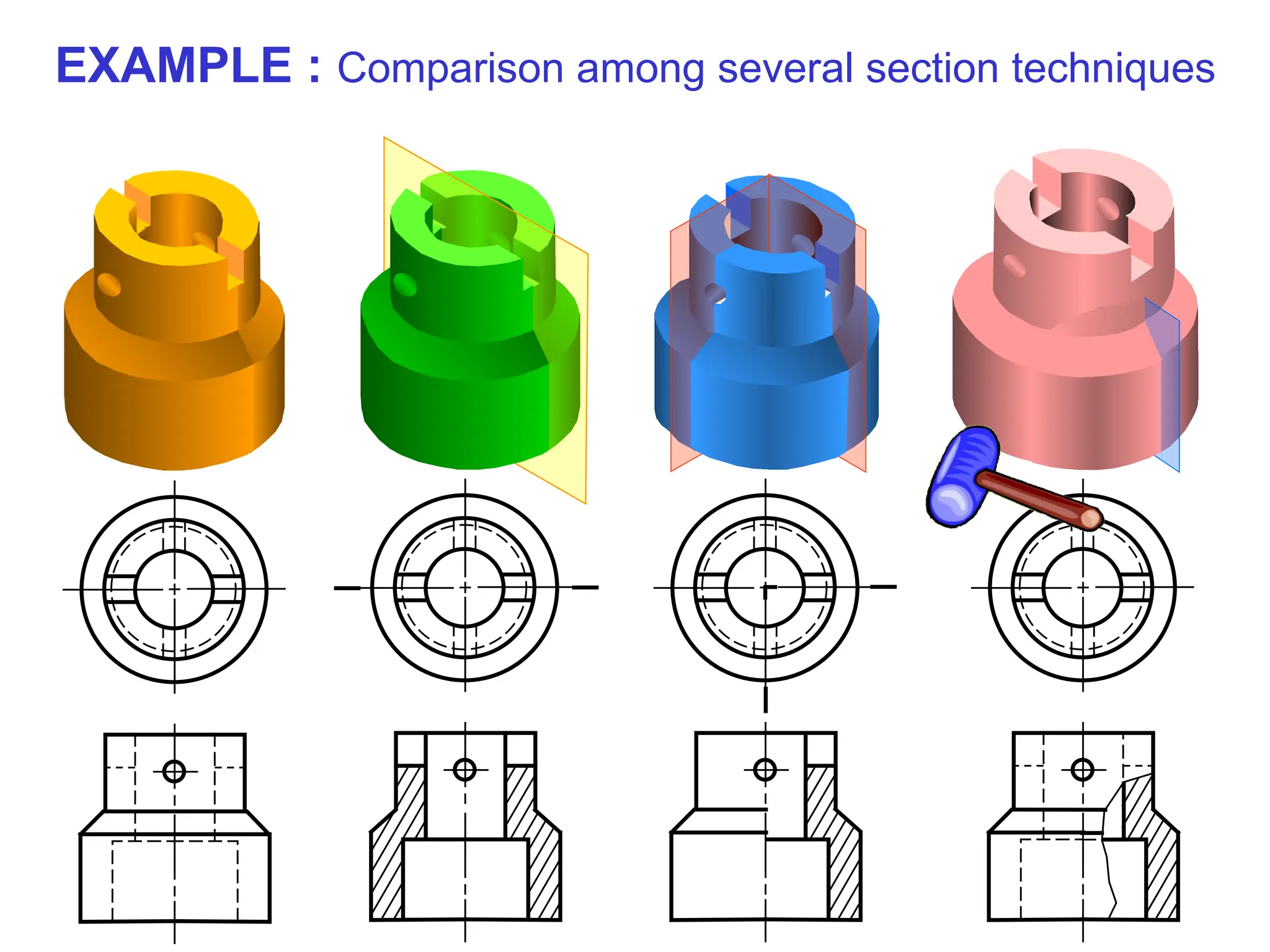
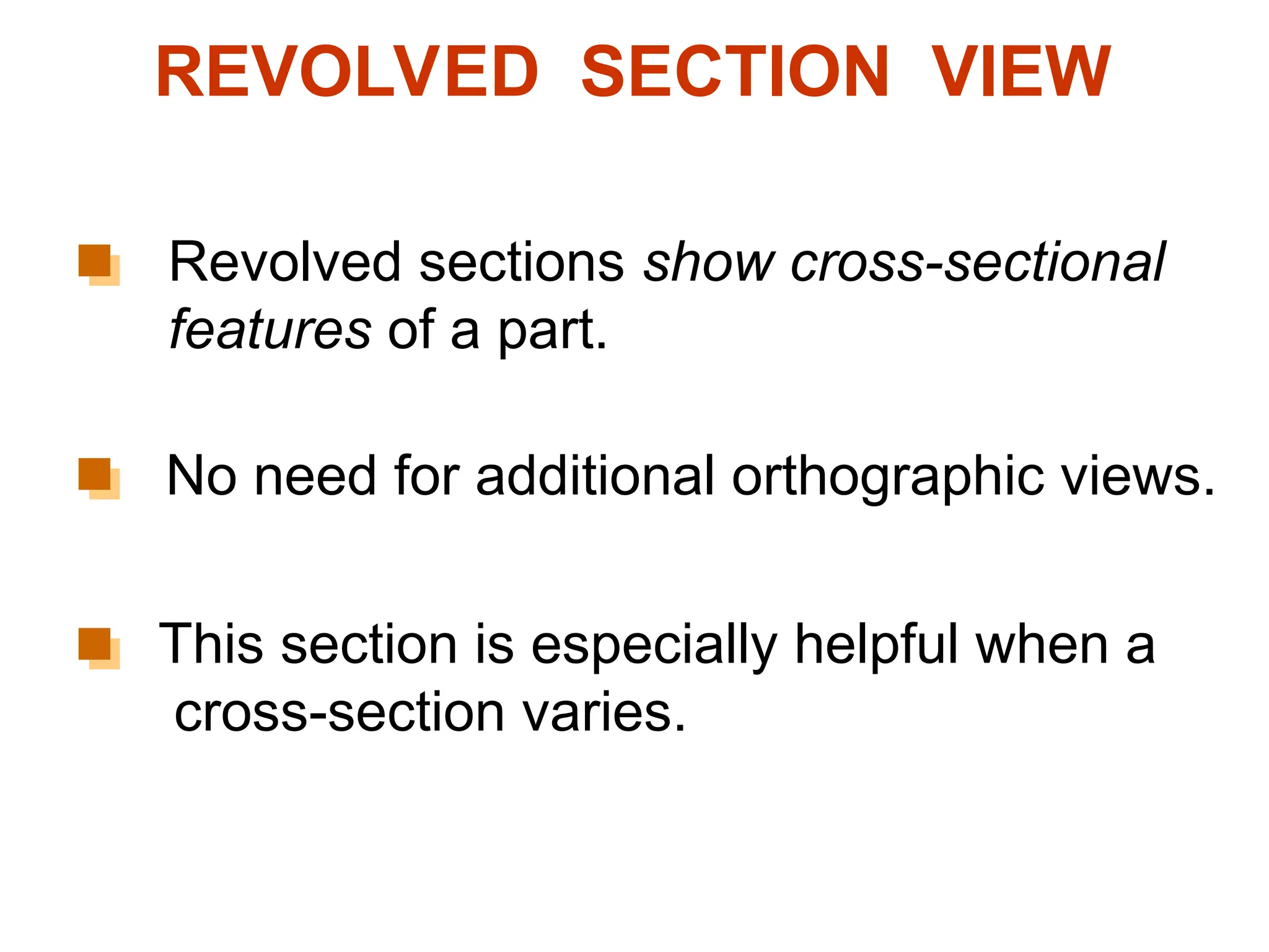
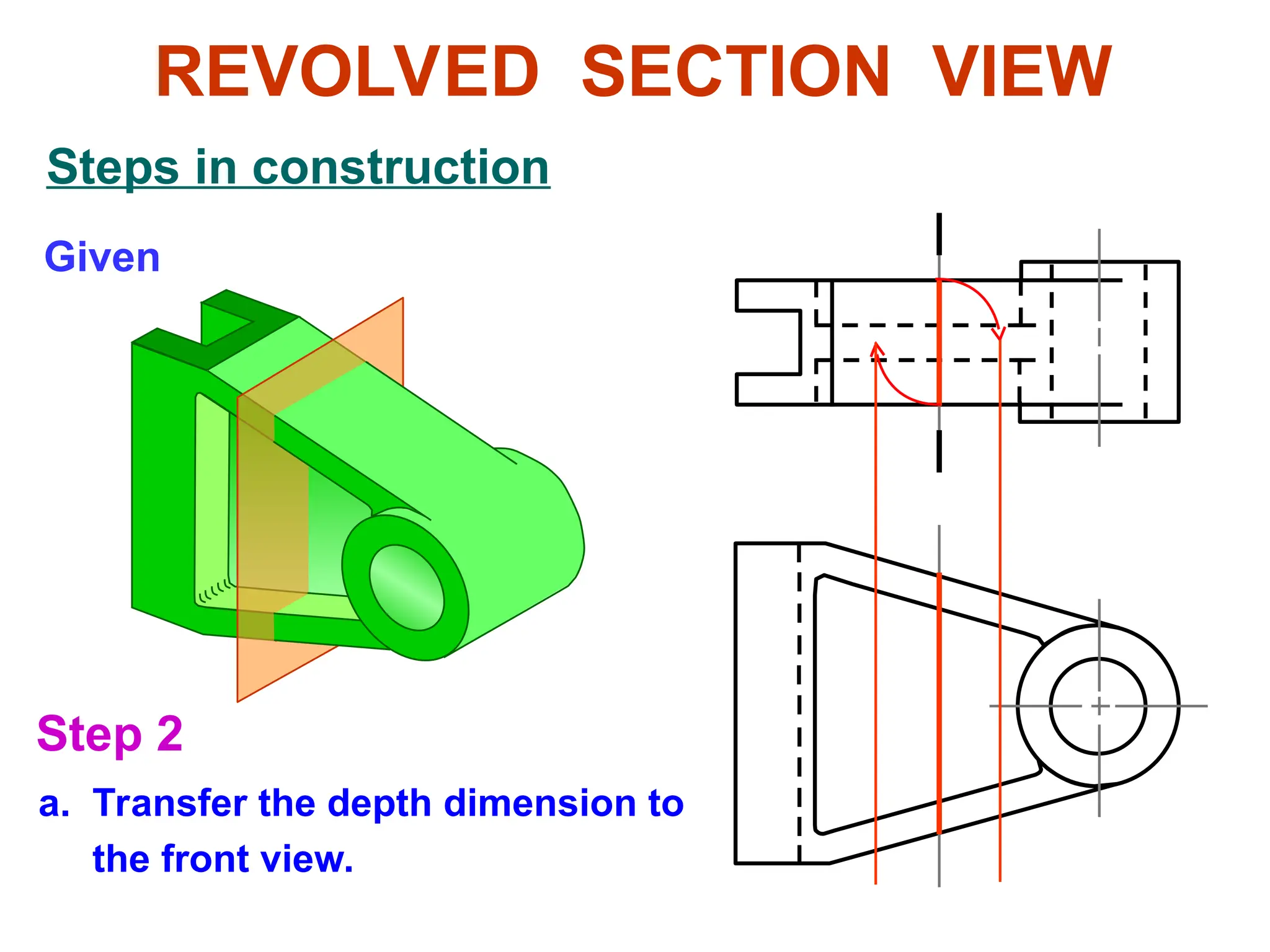
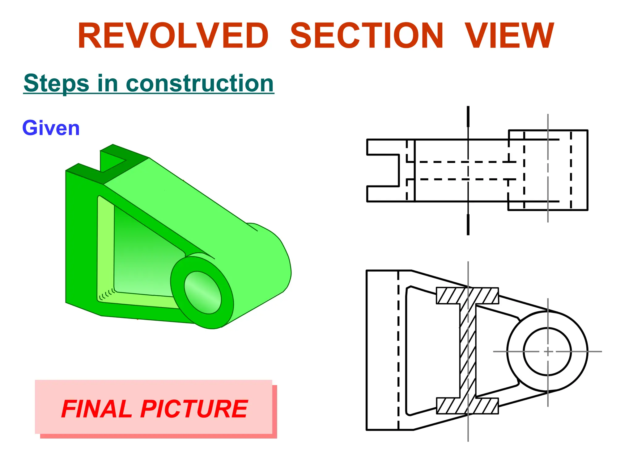
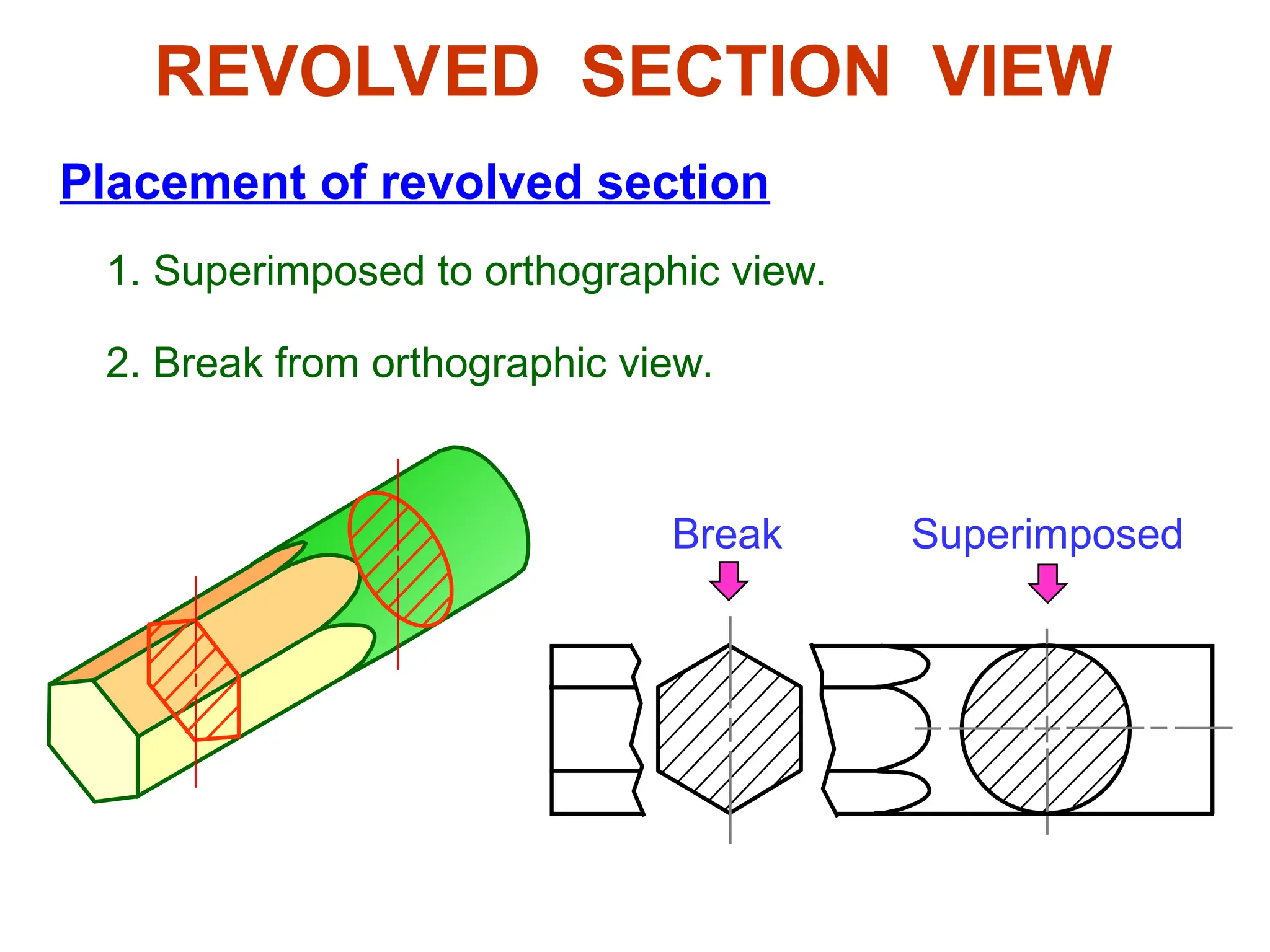
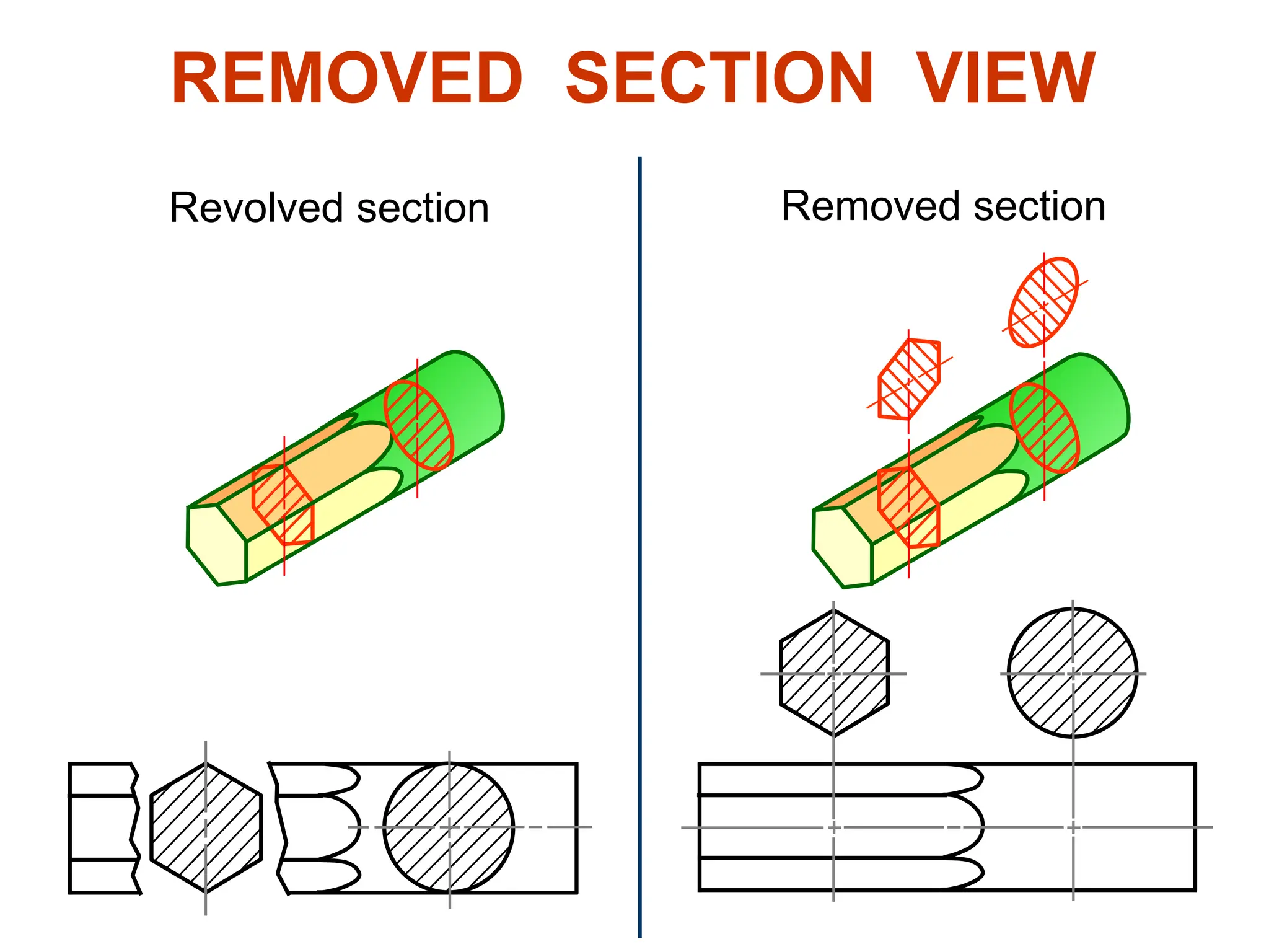
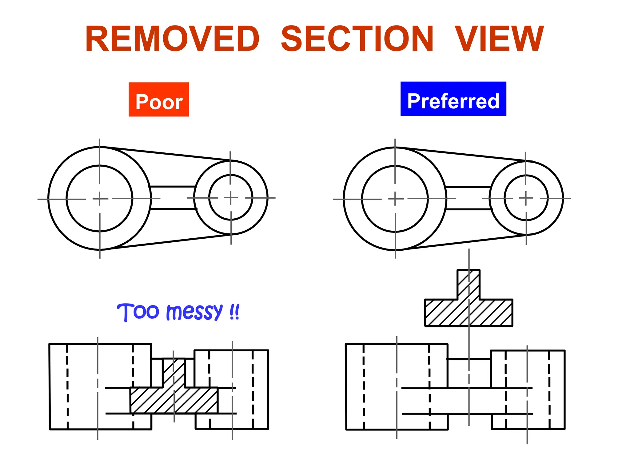
Sectional Views
PURPOSES OF
SECTIONAL VIEWS
Facilitate dimensioning, and
Clarify views by
 reducing or eliminating hidden lines,
 showing the cross sectional’s shape.
Let’s see an example
EXAMPLE
Terminologies and
common practices
Cutting
plane
CUTTING PLANE
Cutting plane line
Cutting plane is a plane that imaginarily cuts
the object to reveal the internal features.
Section lines
Cutting plane line is an edge view of the cutting
plane.
CUTTING PLANE LINE
Indicates the path
of cutting plane.
ANSI
standard
Thick line
Thick line
JIS & ISO
standard
Thin line
CUTTING PLANE LINE STYLES
Viewing
direction
Viewing
direction
Viewing
direction
This course
SECTION LINING
Section lines or cross-hatch lines are used to
indicate the surfaces that are cut by the cutting
plane.
Section
lines
SECTION LINES SYMBOLS
The section lines are different for each of
material’s types.
Cast iron Steel Concrete Sand Wood
For practical purpose, the cast iron symbol is
most oftenly used for any materials.
SECTION LINING PRACTICES
The spaces between lines may vary from 1.5 mm
for small sections to 3 mm for large sections.
COMMON MISTAKES
SECTION LINING PRACTICES
It should not be drawn parallel or perpendicular
to contour of the view.
COMMON MISTAKE
KINDS OF SECTIONS
1. Full section
2. Offset section
3. Half section
4. Broken-out section
5. Revolved section
6. Removed section (detailed section)
FULL SECTION VIEW
The view is made by passing the straight cutting
plane completely through the part.
OFFSET SECTION VIEW
The view is made by passing a bended cutting
plane completely through the part.
Do not show the edge views
of the cutting plane.
TREATMENT OF HIDDEN LINES
Hidden lines are normally omitted from section
views.
HALF SECTION VIEW
The view is made by passing the cutting plane halfway
through an object and remove a quarter of it.
HALF SECTION VIEW
A center line is used to separate the sectioned half
from the unsectioned half of the view.
Hidden line is omitted in unsection half of the view.
The view is made by passing the cutting plane normal
to the viewing direction and removing the portion of an
object in front of it.
BROKEN-OUT SECTION VIEW
A break line is used to separate
the sectioned portion from the
unsectioned portion of the view.
BROKEN-OUT SECTION VIEW
There is no cutting plane line.
Break line is a thin continuous
line and is drawn freehand.
EXAMPLE : Comparison among several section techniques
Revolved sections show cross-sectional
features of a part.
No need for additional orthographic views.
This section is especially helpful when a
cross-section varies.
REVOLVED SECTION VIEW
Basic concept
REVOLVED SECTION VIEW
Basic concept
Given
Step 1
a. Assign position of cutting plane.
b. Draw axis of rotation in front view.
Steps in construction
REVOLVED SECTION VIEW
Edge view of
Edge view of
cross-section
cross-section
Steps in construction
Given
a. Transfer the depth dimension to
the front view.
REVOLVED SECTION VIEW
Step 2
Steps in construction
Given
REVOLVED SECTION VIEW
a. Draw the revolved section.
Step 3
b. Add section lines.
Steps in construction
Given
REVOLVED SECTION VIEW
FINAL PICTURE
Placement of revolved section
1. Superimposed to orthographic view.
Superimposed
Break
2. Break from orthographic view.
REVOLVED SECTION VIEW
6. Removed section
Removed section is revolved section.
Used where space does not enough for
revolved section
Can be located elsewhere on a drawing
with properly labeled
REMOVED SECTION VIEW
Section view is shown outside the view.
Example : Revolved vs. removed sections.
Revolved section Removed section
REMOVED SECTION VIEW
Example : Situation that removed section is preferred.
REMOVED SECTION VIEW
Preferred
Poor
Too messy !!

Lecture 6-Engineering Darwing: Sectional views.ppt

  • 1.
  • 2.
    PURPOSES OF SECTIONAL VIEWS Facilitatedimensioning, and Clarify views by  reducing or eliminating hidden lines,  showing the cross sectional’s shape. Let’s see an example
  • 3.
  • 4.
  • 5.
    Cutting plane CUTTING PLANE Cutting planeline Cutting plane is a plane that imaginarily cuts the object to reveal the internal features. Section lines
  • 6.
    Cutting plane lineis an edge view of the cutting plane. CUTTING PLANE LINE Indicates the path of cutting plane.
  • 7.
    ANSI standard Thick line Thick line JIS& ISO standard Thin line CUTTING PLANE LINE STYLES Viewing direction Viewing direction Viewing direction This course
  • 8.
    SECTION LINING Section linesor cross-hatch lines are used to indicate the surfaces that are cut by the cutting plane. Section lines
  • 9.
    SECTION LINES SYMBOLS Thesection lines are different for each of material’s types. Cast iron Steel Concrete Sand Wood For practical purpose, the cast iron symbol is most oftenly used for any materials.
  • 10.
    SECTION LINING PRACTICES Thespaces between lines may vary from 1.5 mm for small sections to 3 mm for large sections. COMMON MISTAKES
  • 11.
    SECTION LINING PRACTICES Itshould not be drawn parallel or perpendicular to contour of the view. COMMON MISTAKE
  • 12.
    KINDS OF SECTIONS 1.Full section 2. Offset section 3. Half section 4. Broken-out section 5. Revolved section 6. Removed section (detailed section)
  • 13.
    FULL SECTION VIEW Theview is made by passing the straight cutting plane completely through the part.
  • 14.
    OFFSET SECTION VIEW Theview is made by passing a bended cutting plane completely through the part. Do not show the edge views of the cutting plane.
  • 15.
    TREATMENT OF HIDDENLINES Hidden lines are normally omitted from section views.
  • 16.
    HALF SECTION VIEW Theview is made by passing the cutting plane halfway through an object and remove a quarter of it.
  • 17.
    HALF SECTION VIEW Acenter line is used to separate the sectioned half from the unsectioned half of the view. Hidden line is omitted in unsection half of the view.
  • 18.
    The view ismade by passing the cutting plane normal to the viewing direction and removing the portion of an object in front of it. BROKEN-OUT SECTION VIEW
  • 19.
    A break lineis used to separate the sectioned portion from the unsectioned portion of the view. BROKEN-OUT SECTION VIEW There is no cutting plane line. Break line is a thin continuous line and is drawn freehand.
  • 20.
    EXAMPLE : Comparisonamong several section techniques
  • 21.
    Revolved sections showcross-sectional features of a part. No need for additional orthographic views. This section is especially helpful when a cross-section varies. REVOLVED SECTION VIEW
  • 22.
  • 23.
  • 24.
    Given Step 1 a. Assignposition of cutting plane. b. Draw axis of rotation in front view. Steps in construction REVOLVED SECTION VIEW Edge view of Edge view of cross-section cross-section
  • 25.
    Steps in construction Given a.Transfer the depth dimension to the front view. REVOLVED SECTION VIEW Step 2
  • 26.
    Steps in construction Given REVOLVEDSECTION VIEW a. Draw the revolved section. Step 3 b. Add section lines.
  • 27.
    Steps in construction Given REVOLVEDSECTION VIEW FINAL PICTURE
  • 28.
    Placement of revolvedsection 1. Superimposed to orthographic view. Superimposed Break 2. Break from orthographic view. REVOLVED SECTION VIEW
  • 29.
    6. Removed section Removedsection is revolved section. Used where space does not enough for revolved section Can be located elsewhere on a drawing with properly labeled REMOVED SECTION VIEW Section view is shown outside the view.
  • 30.
    Example : Revolvedvs. removed sections. Revolved section Removed section REMOVED SECTION VIEW
  • 31.
    Example : Situationthat removed section is preferred. REMOVED SECTION VIEW Preferred Poor Too messy !!