The document discusses kinematics and mechanisms. It defines kinematics as the study of motion geometry and mechanisms as devices that transfer motion and forces. It describes the components of mechanisms including links, joints, frames and discusses revolute and sliding joints. Higher order joints like cam and gear joints are described. Degrees of freedom, which represent the number of independent inputs to position all links, are discussed along with Gruebler's equation for calculating degrees of freedom. Examples of kinematic diagrams for mechanisms are provided along with computing degrees of freedom.
Machines and MechanismsMachinesaredevices used to accomplish work. Mechanism is the mechanical portion of a machine that has the function of transffering motion and forces from a power source to an output.Reference: Machines and Mechanisms Applied Kinematics by David H. Myszka
Kinematics and KinematicAnalysisKinematics is the study of the geometry of motion.Kinematic Analysis deals with the determination of position, displacement, rotation, speed, velocity, and acceleration.Reference: Machines and Mechanisms Applied Kinematics by David H. Myszka
5.
TerminologiesPlanar mechanism aremechanisms that exhibit motion such that parts move in parallel plane.Linkages is a mechanism where all parts are connected to form a closed chain.Frame is one part of the closed chain that exhibits no motion and serves as a reference for the motion of all other parts.Reference: Machines and Mechanisms Applied Kinematics by David H. Myszka
6.
TerminologiesLinks are individualparts of the mechanisms. They are rigid bodies and are connected with other links to transmit motion and forces.Joint is a movable connection between links and allows relative motion between links.Reference: Machines and Mechanisms Applied Kinematics by David H. Myszka
7.
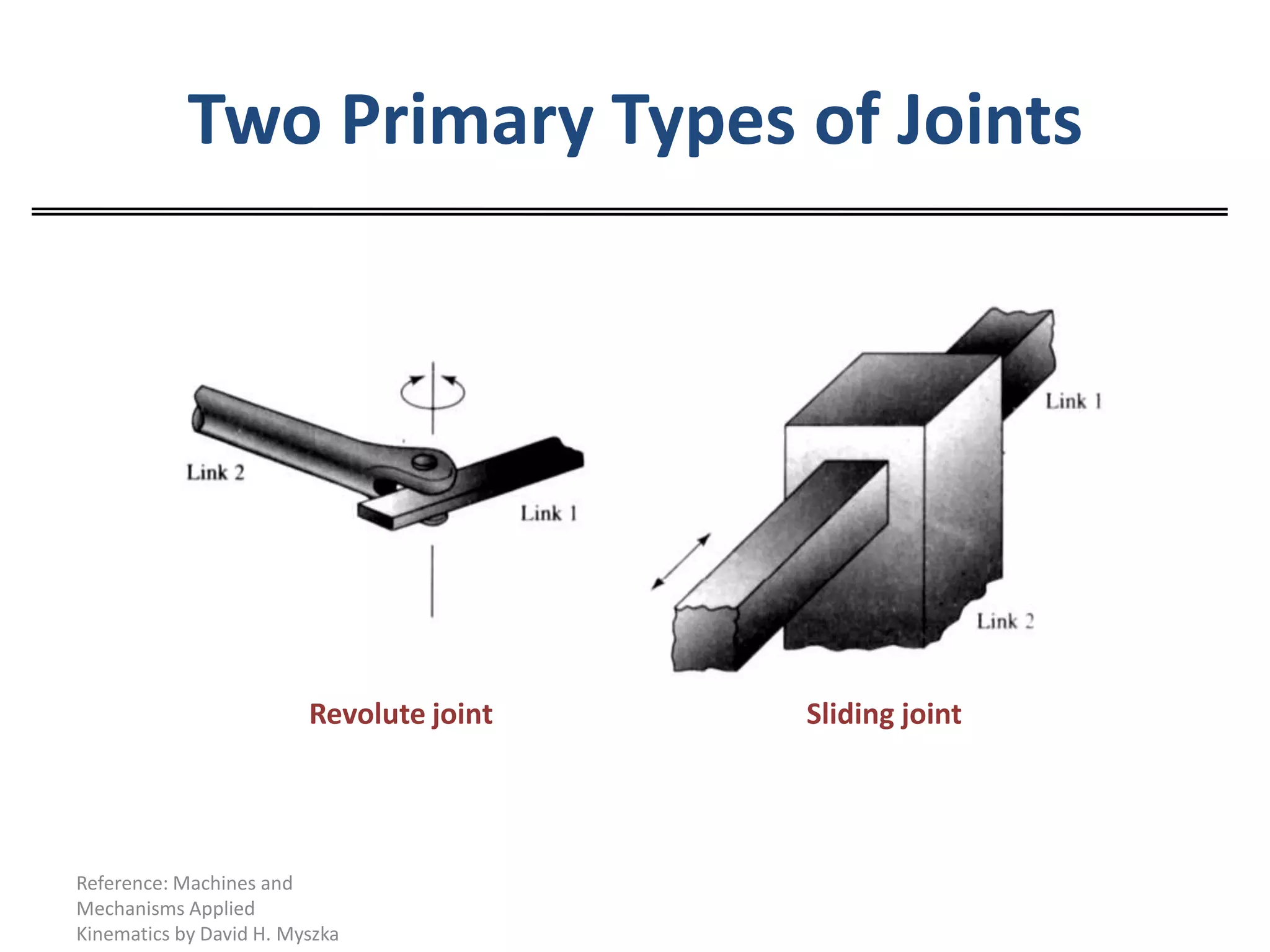
Two Primary Typesof JointsRevolute jointSliding jointReference: Machines and Mechanisms Applied Kinematics by David H. Myszka
8.
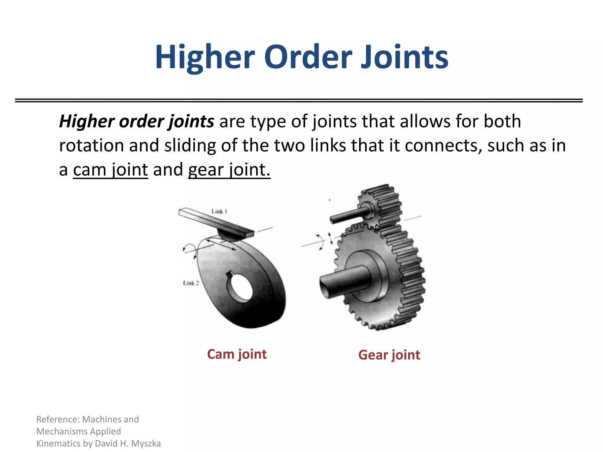
Higher Order Joints Higherorder joints are type of joints that allows for both rotation and sliding of the two links that it connects, such as in a cam joint and gear joint.Cam jointGear jointReference: Machines and Mechanisms Applied Kinematics by David H. Myszka
9.
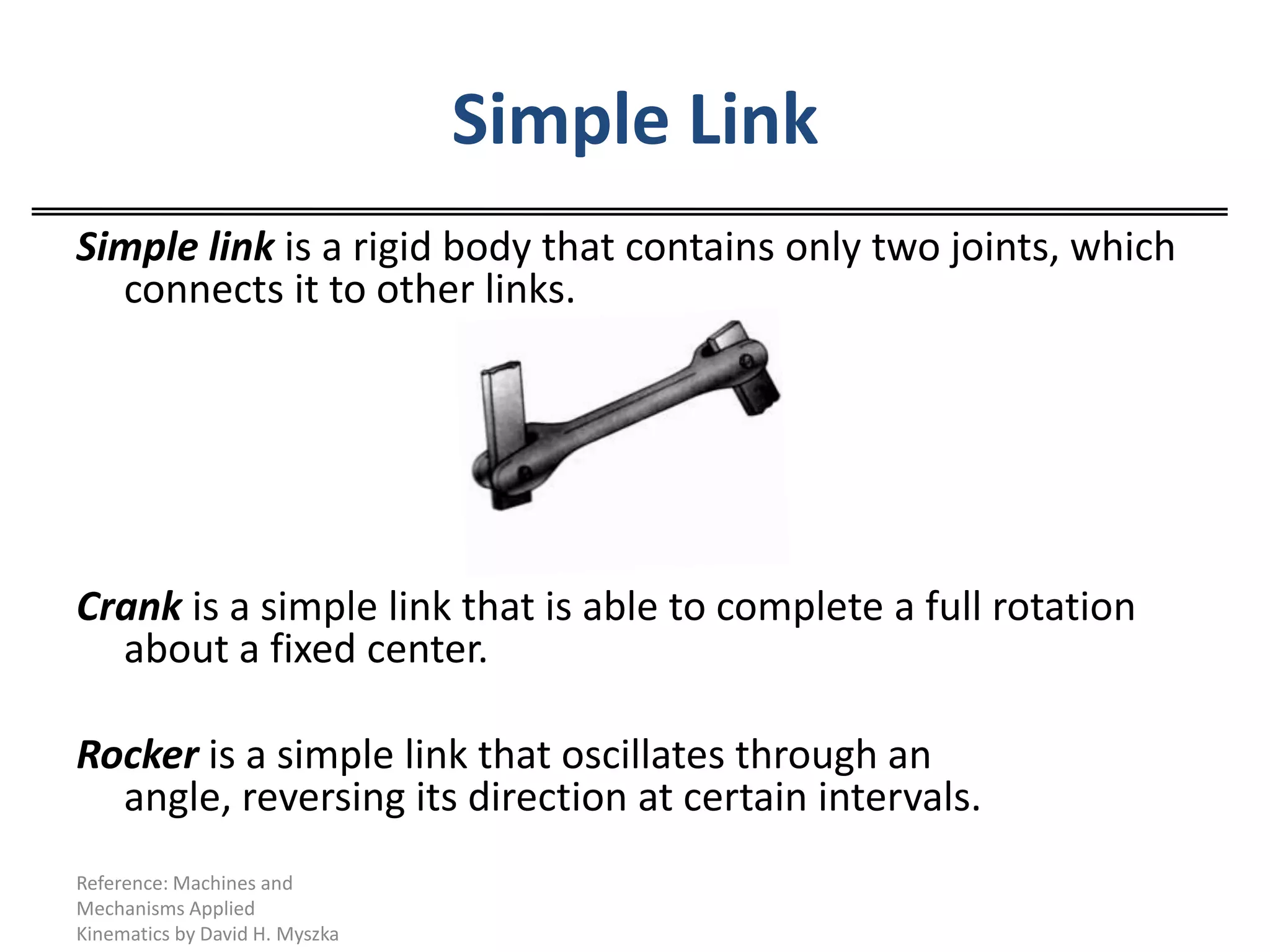
Simple LinkSimple linkis a rigid body that contains only two joints, which connects it to other links.Crank is a simple link that is able to complete a full rotation about a fixed center.Rocker is a simple link that oscillates through an angle, reversing its direction at certain intervals.Reference: Machines and Mechanisms Applied Kinematics by David H. Myszka
10.
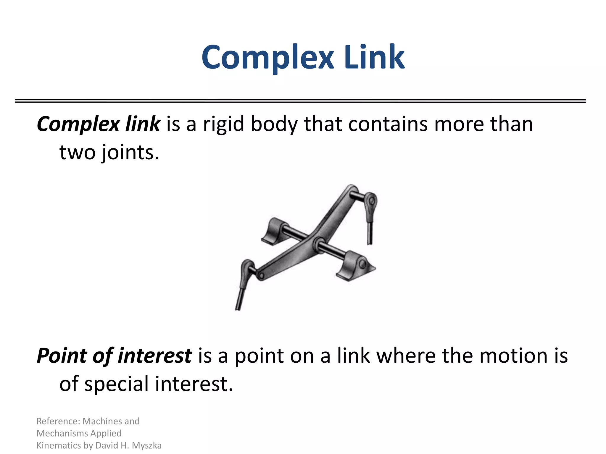
Complex LinkComplex linkis a rigid body that contains more than two joints.Point of interest is a point on a link where the motion is of special interest. Reference: Machines and Mechanisms Applied Kinematics by David H. Myszka
11.
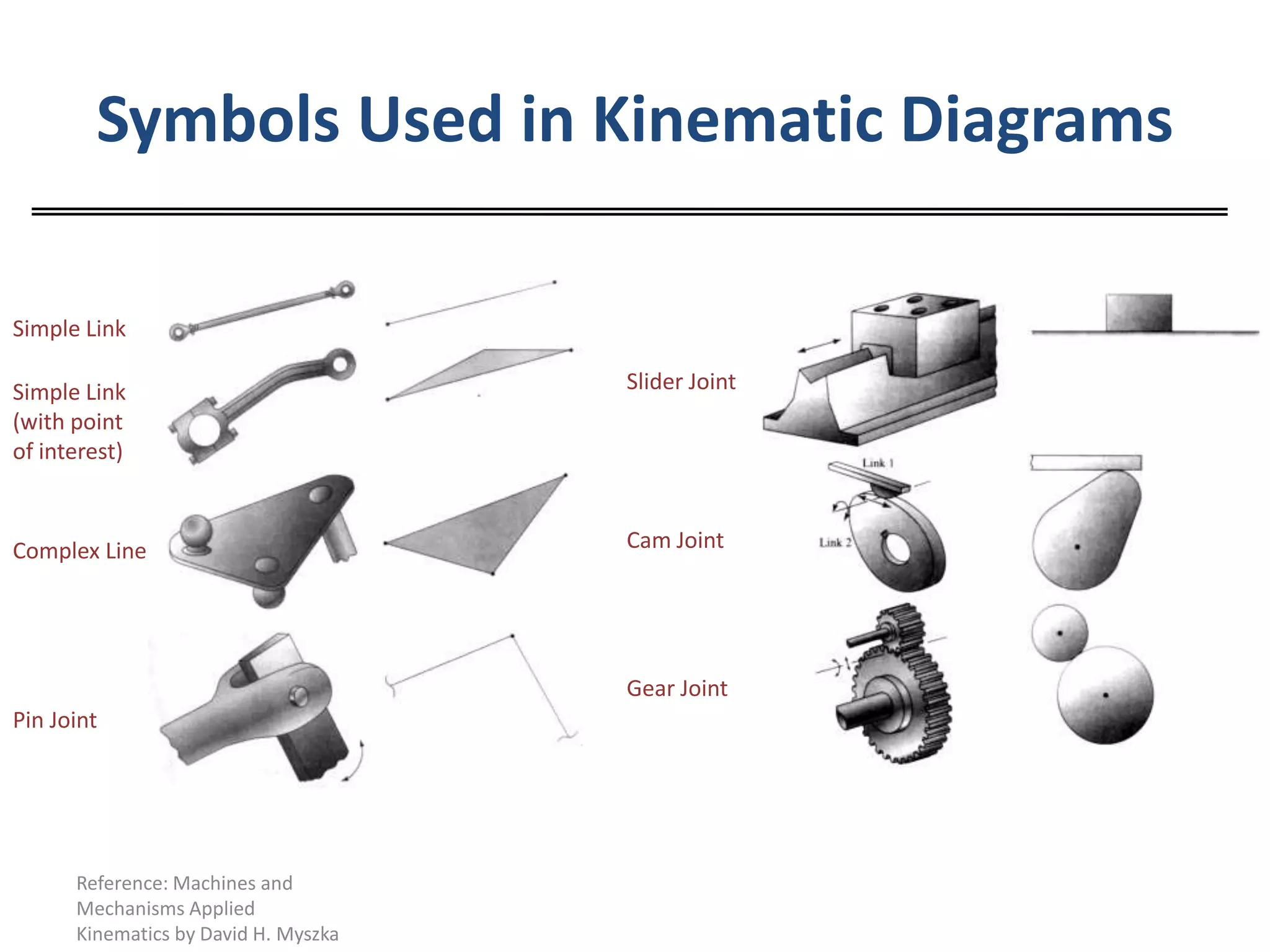
Symbols Used inKinematic DiagramsReference: Machines and Mechanisms Applied Kinematics by David H. MyszkaSimple LinkSlider JointSimple Link (with point of interest)Cam JointComplex LineGear JointPin Joint
12.
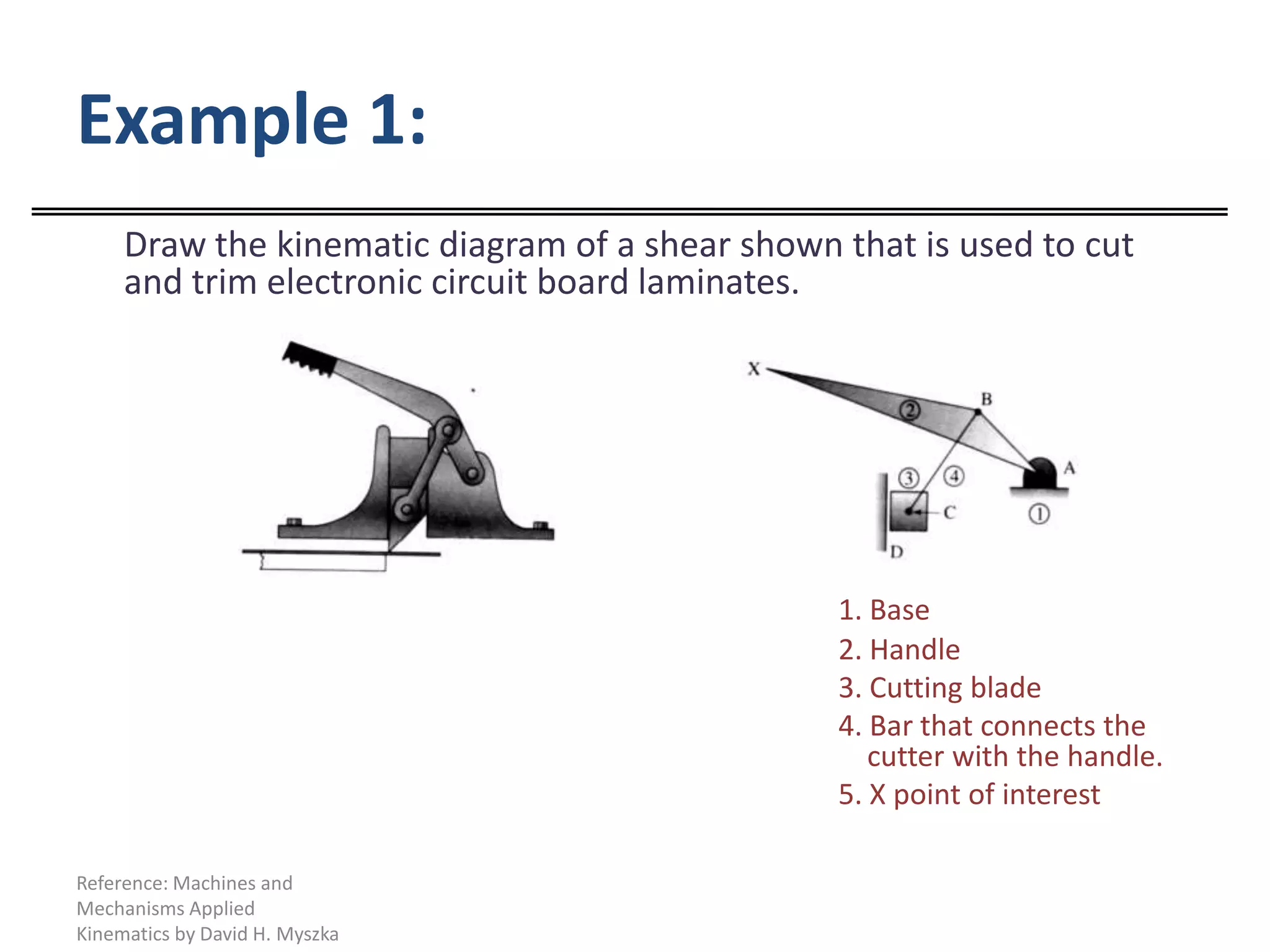
Example 1:Draw thekinematic diagram of a shear shown that is used to cut and trim electronic circuit board laminates.1. Base 2. Handle 3. Cutting blade 4. Bar that connects the cutter with the handle. 5. X point of interestReference: Machines and Mechanisms Applied Kinematics by David H. Myszka
13.
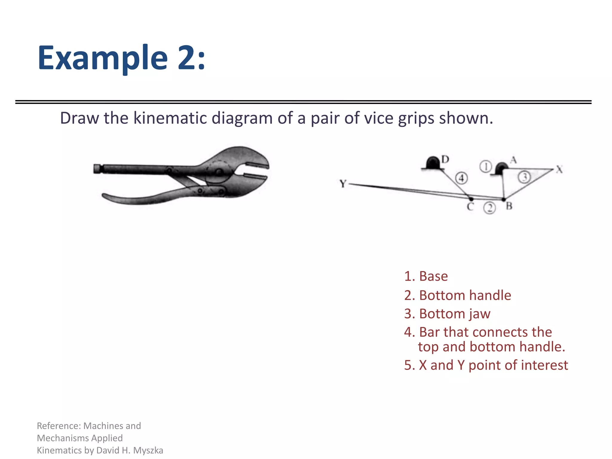
Example 2:Draw thekinematic diagram of a pair of vice grips shown. 1. Base 2. Bottom handle 3. Bottom jaw 4. Bar that connects the top and bottom handle. 5. X and Y point of interestReference: Machines and Mechanisms Applied Kinematics by David H. Myszka
14.
Degree of Freedom Degreeof Freedom or Mobility “F” is the number of independent inputs required to precisely position all links of the mechanism with respect to the ground. It can also be defined as the numbers of drivers required to operate the mechanism.Reference: Machines and Mechanisms Applied Kinematics by David H. Myszka
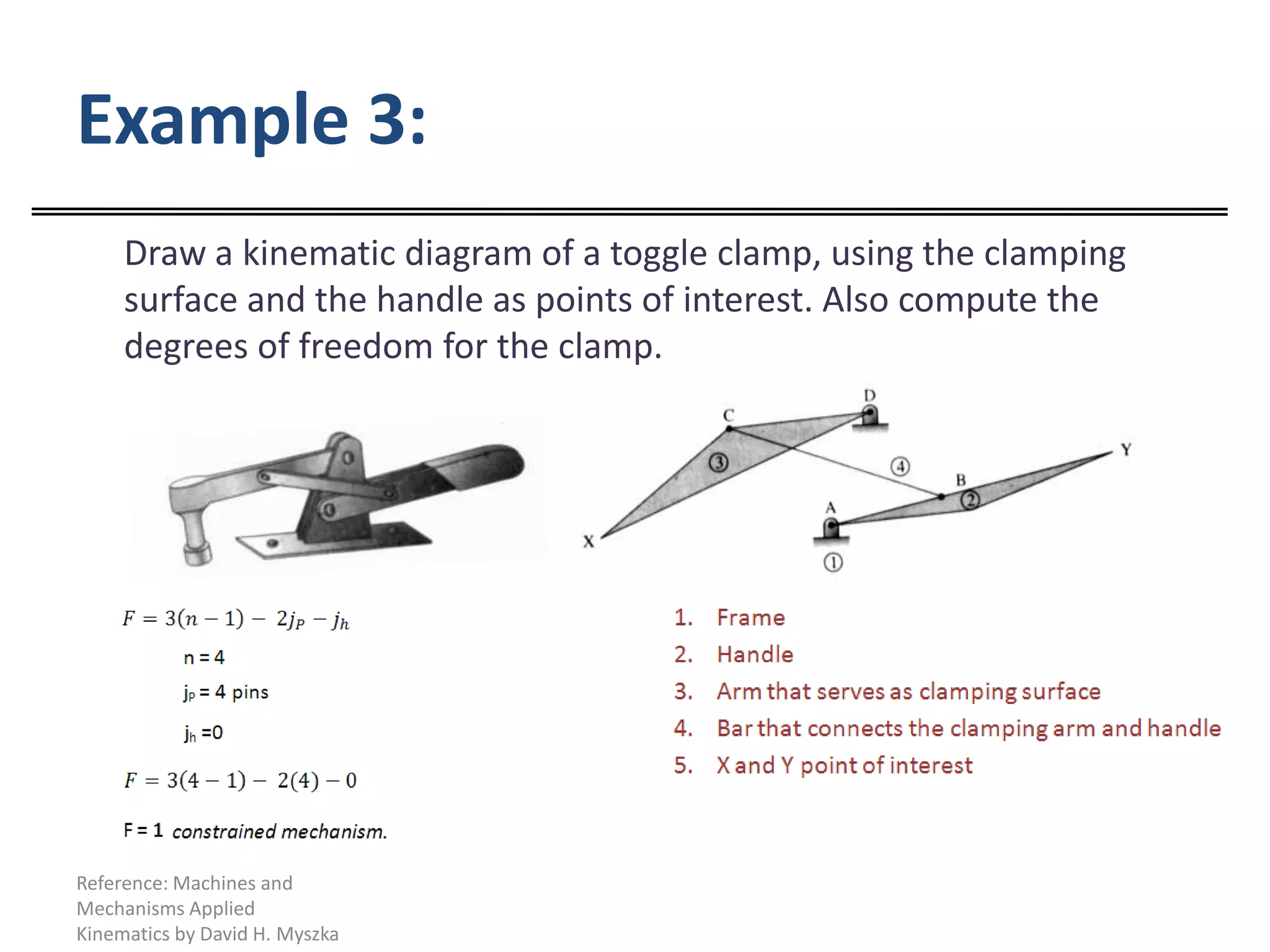
Example 3: Draw akinematic diagram of a toggle clamp, using the clamping surface and the handle as points of interest. Also compute the degrees of freedom for the clamp.Reference: Machines and Mechanisms Applied Kinematics by David H. Myszka
17.
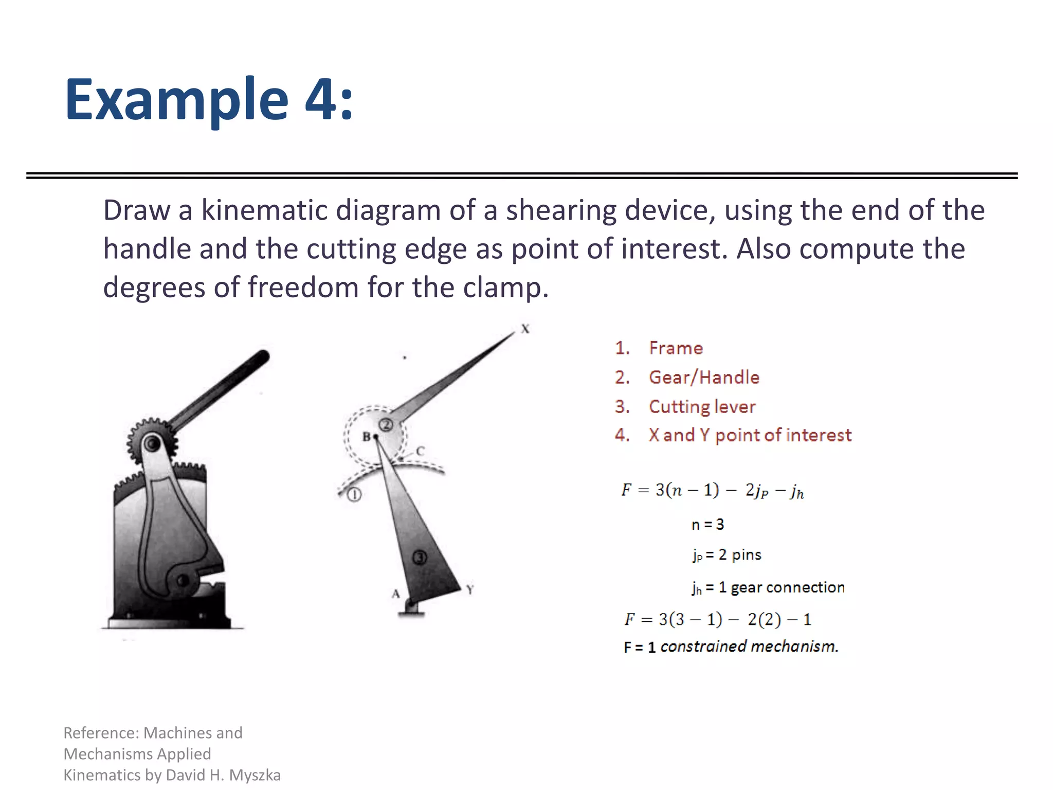
Example 4: Draw akinematic diagram of a shearing device, using the end of the handle and the cutting edge as point of interest. Also compute the degrees of freedom for the clamp.Reference: Machines and Mechanisms Applied Kinematics by David H. Myszka


![[10] degrees of freedom assignment](https://cdn.slidesharecdn.com/ss_thumbnails/10degreesoffreedomassignment-160926065131-thumbnail.jpg?width=640&height=640&fit=bounds)


![Tom[unit 1]](https://cdn.slidesharecdn.com/ss_thumbnails/tomunit-1-140122191249-phpapp02-thumbnail.jpg?width=640&height=640&fit=bounds)


