1. The document provides lecture notes on kinematics of machinery, covering topics such as mechanisms, kinematic pairs, mobility, and straight line motion mechanisms.
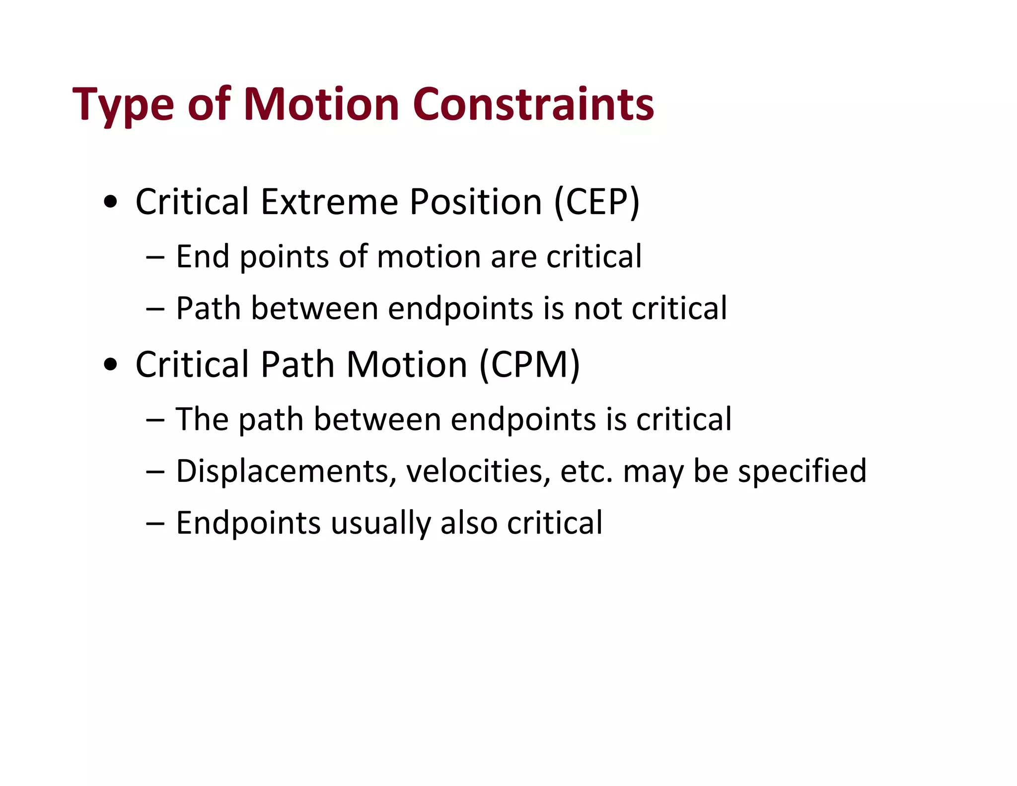
2. Key concepts discussed include degrees of freedom, links and joints, kinematic chains, mechanisms versus machines, and types of constrained motion. Common mechanisms like slider crank and four bar linkages are also introduced.
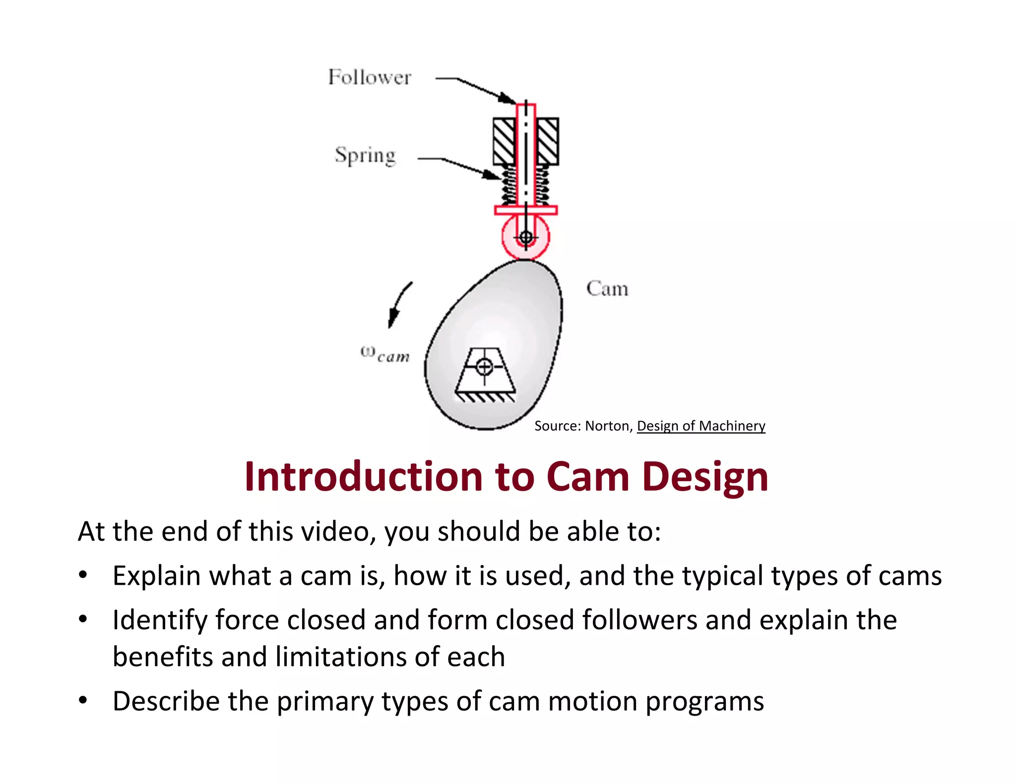
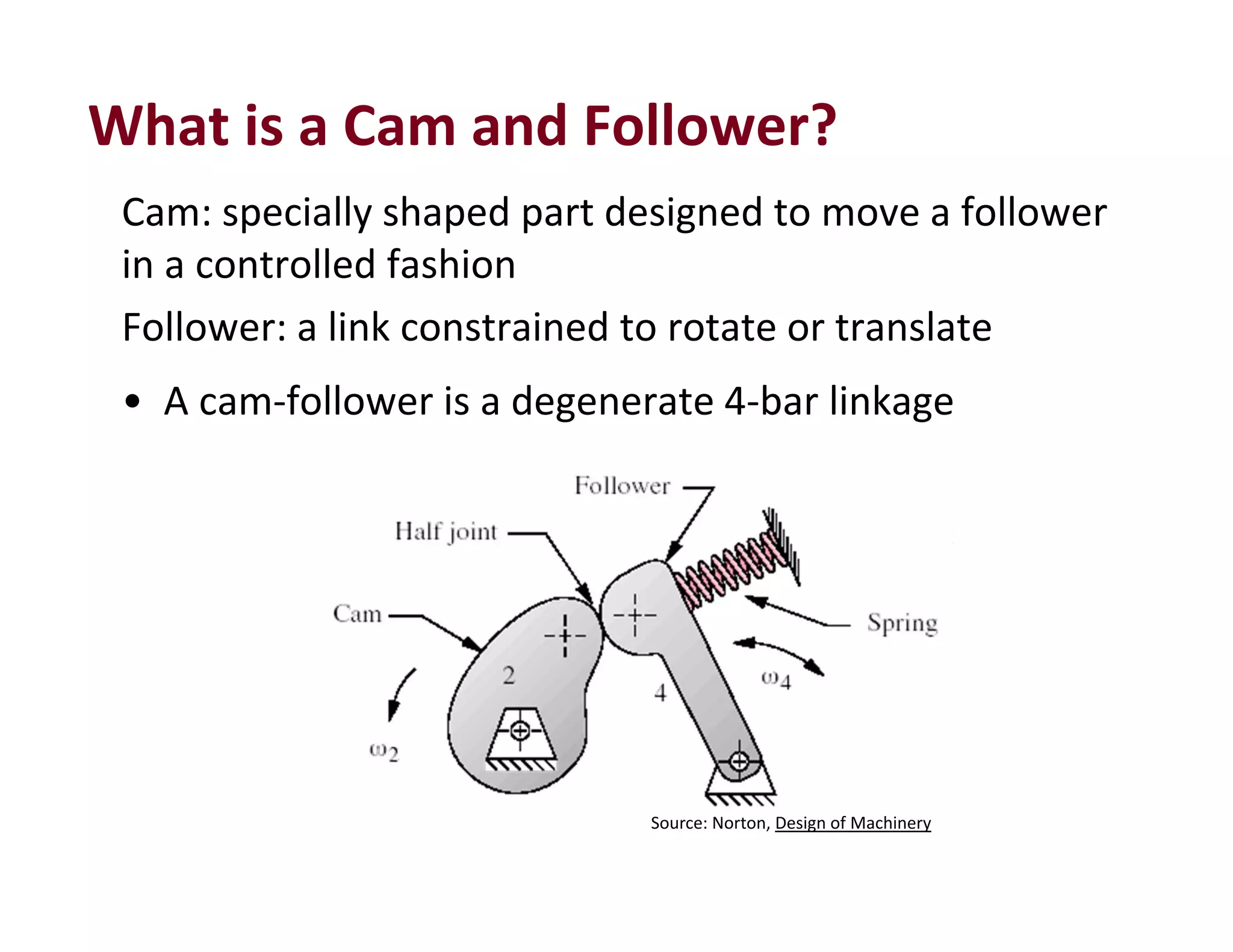
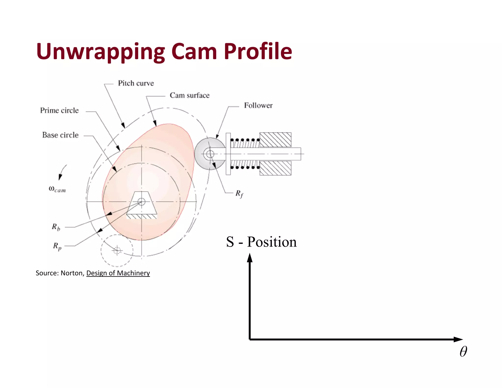
3. The objectives of the course are to understand basic kinematic principles, analyze various mechanisms for displacement, velocity and acceleration, and examine gears, gear trains, cams and other machine elements. The course covers analysis of mechanisms using methods like velocity and acceleration diagrams, instantaneous centers, and cam profiles.


![104
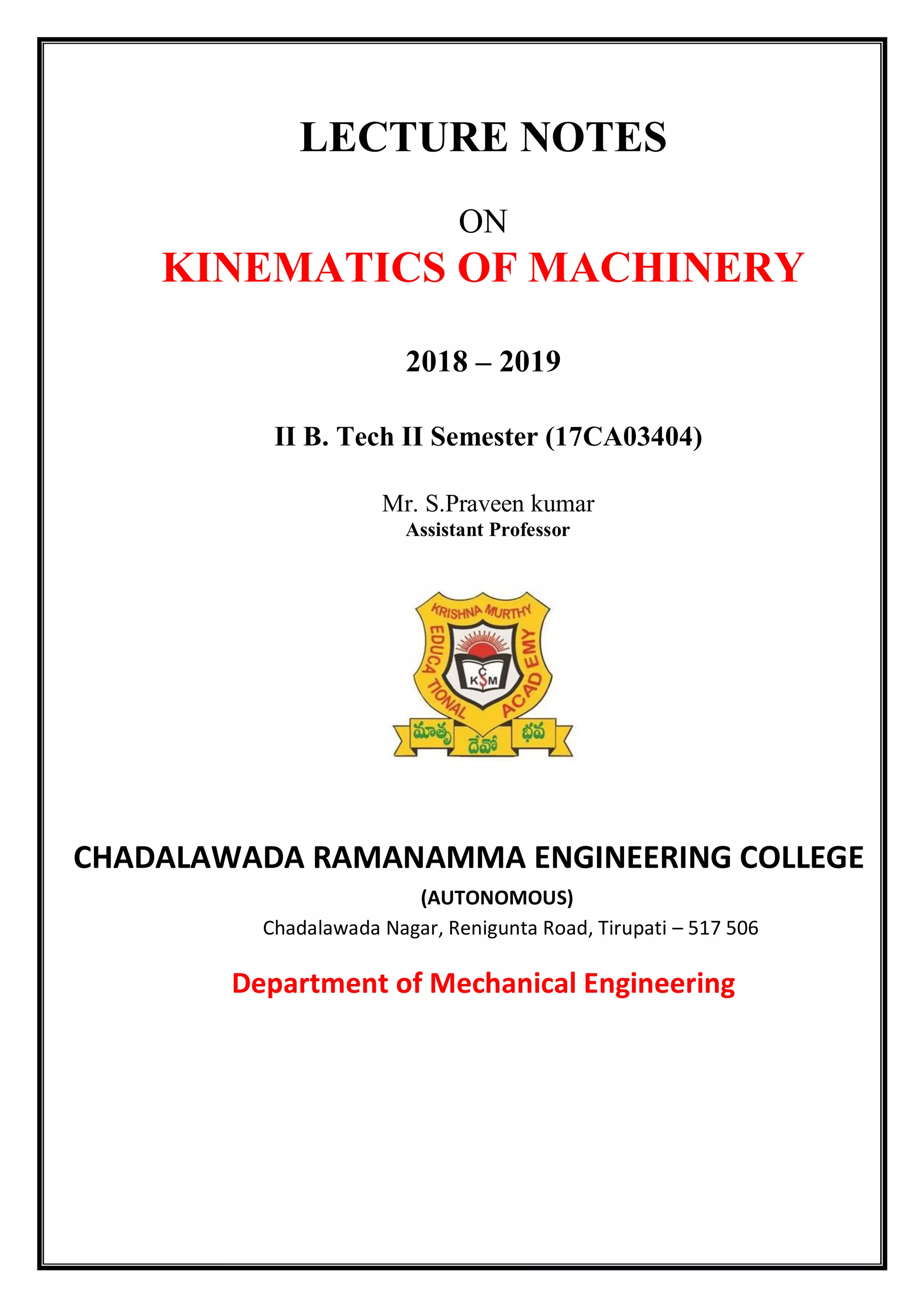
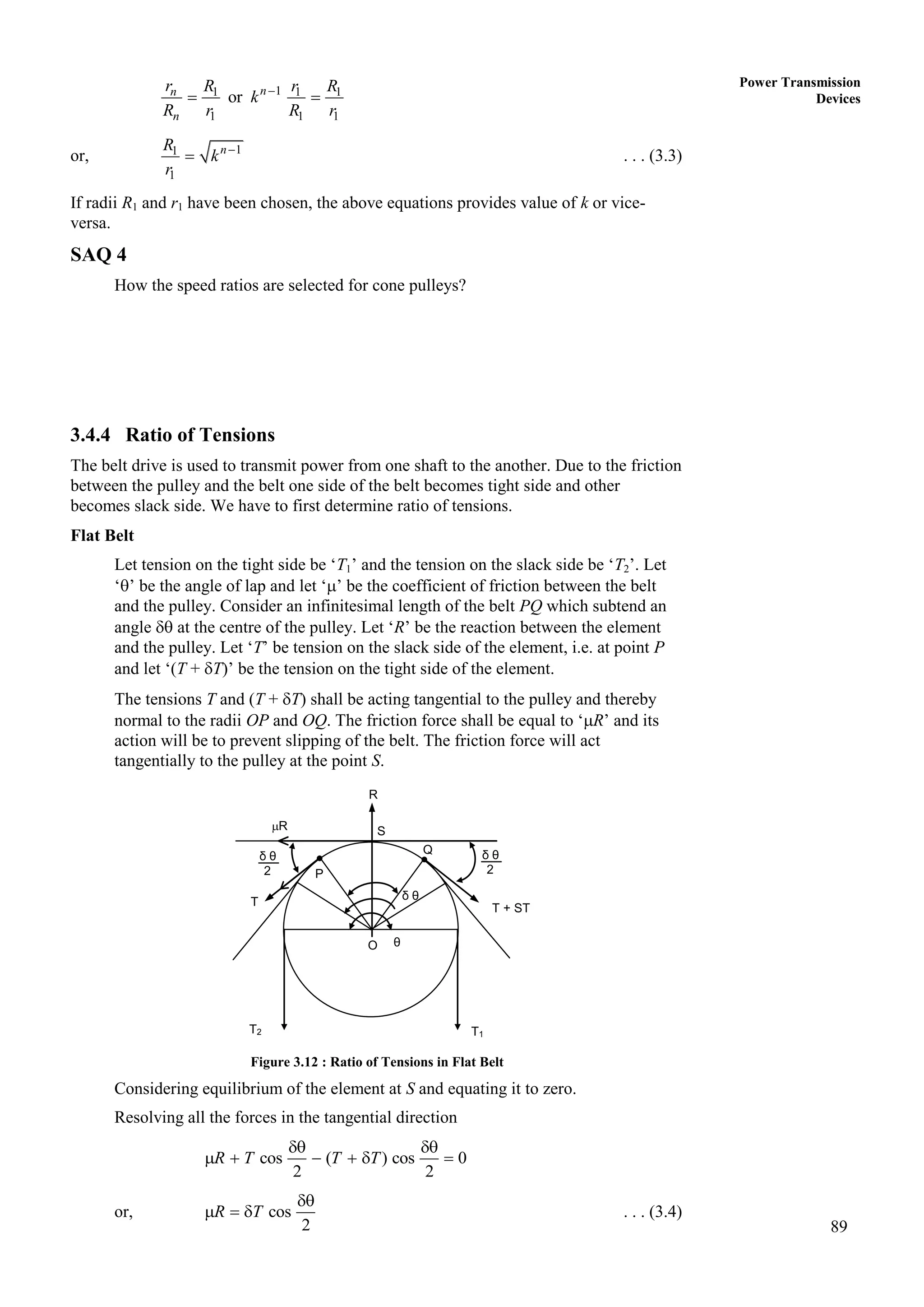
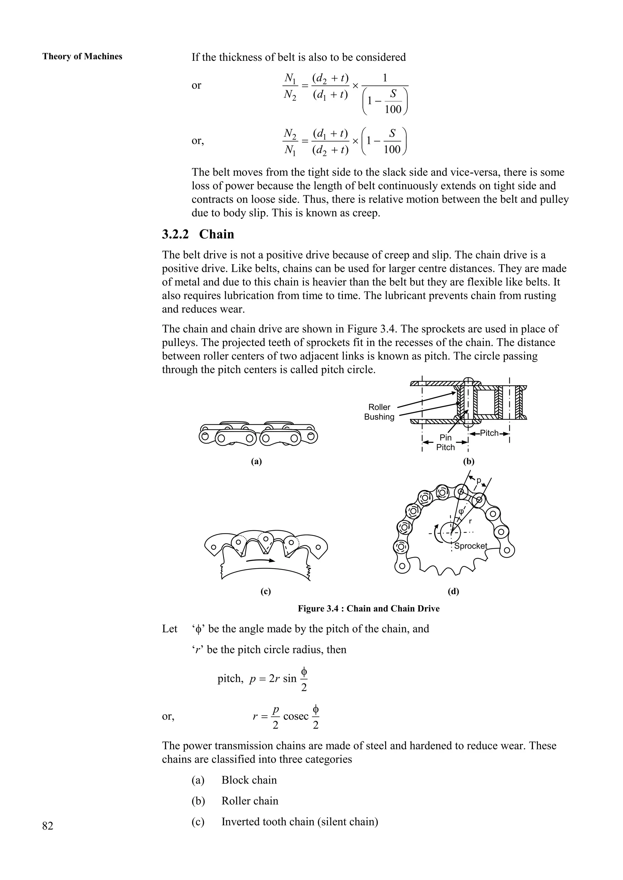
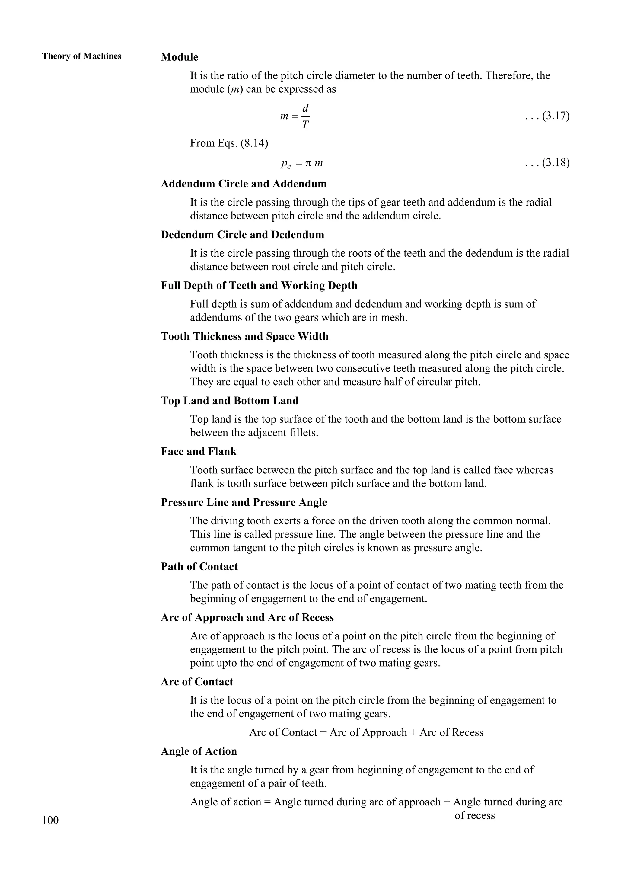
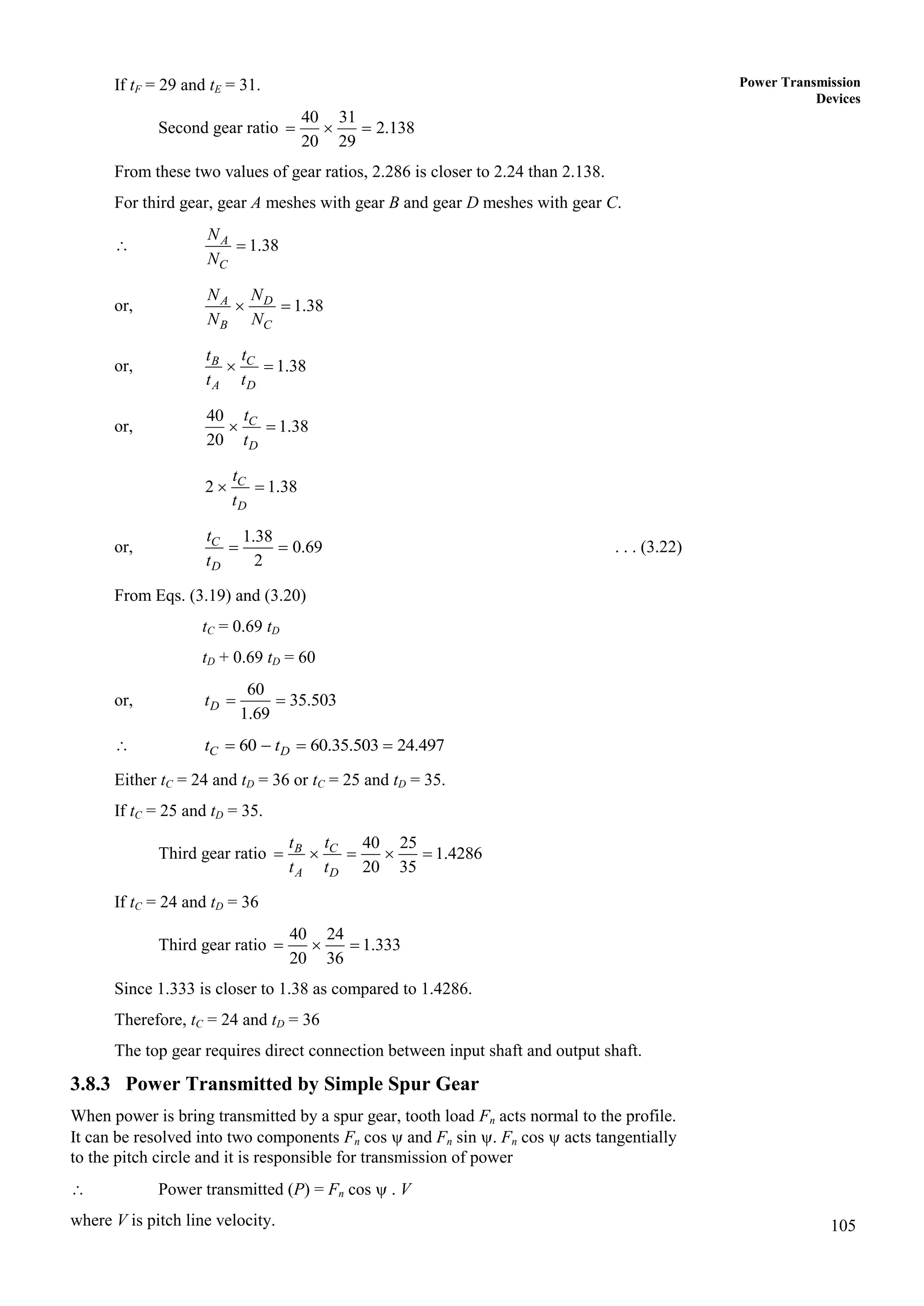
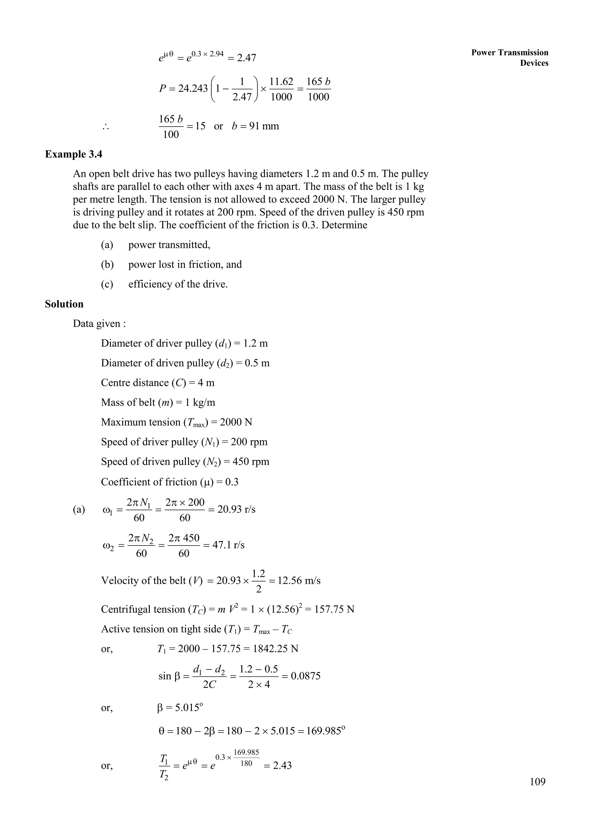
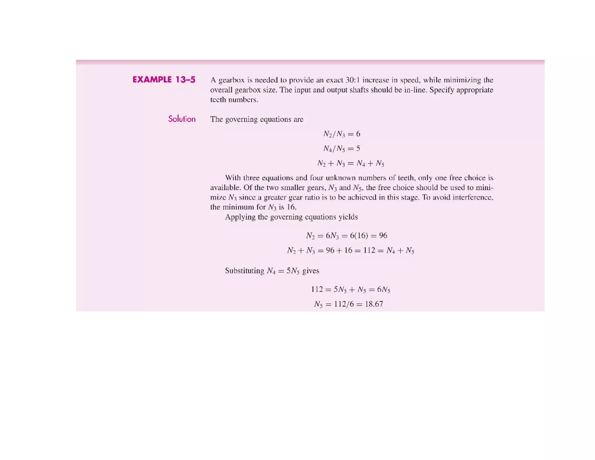
Theory of Machines For providing first gear ratio, gear A meshes with gear B and gear H meshes with
gear G.
Speed of engine shaft
First gear ratio =
Speed of output shaft
A A H A H
G H G B G
N N N N N
N N N N N
[i.e. NB = NH]
G
B
A H
t
t
t t
For smallest size of gear box G
B
A H
t
t
t t
4.0 2.0
G
B
A H
t
t
t t
If tA = 20 teeth tH = 20
tB = 2 20 = 40 teeth and tG = 20 2 = 40 teeth
Since centre distance should be same
A B C D E F H G
t t t t t t t t
40 20 60
C D
t t
. . . (3.19)
60
E F
t t
. . . (3.20)
For second gear, gear A meshes with gear B and gear E meshes with gear F.
2.24
A
G
N
N
or, 2.24
A F
B E
N N
N N
2.24
B E
A F
t t
t t
or, 2 2.24
F
G
t
t
or,
2.24
1.12
2
E
F
t
t
. . . (3.21)
From Eqs. (10.2) and (10.3)
1.12 60
F F
t t
or,
60
28.3 60
2.12
F E F
t t t
or, 60 28.3 31.7
E
t
Since number of teeth have to be in full number. Therefore, tF can be either 28 or
29 and tE can be either 31 or 32. If tF = 28 and tE = 32.
Second gear ratio
40 32
2.286
20 28
A E
B F
t t
t t
](https://image.slidesharecdn.com/komlecturenotes-210205072416/75/Kom-lecture-notes-61-2048.jpg)
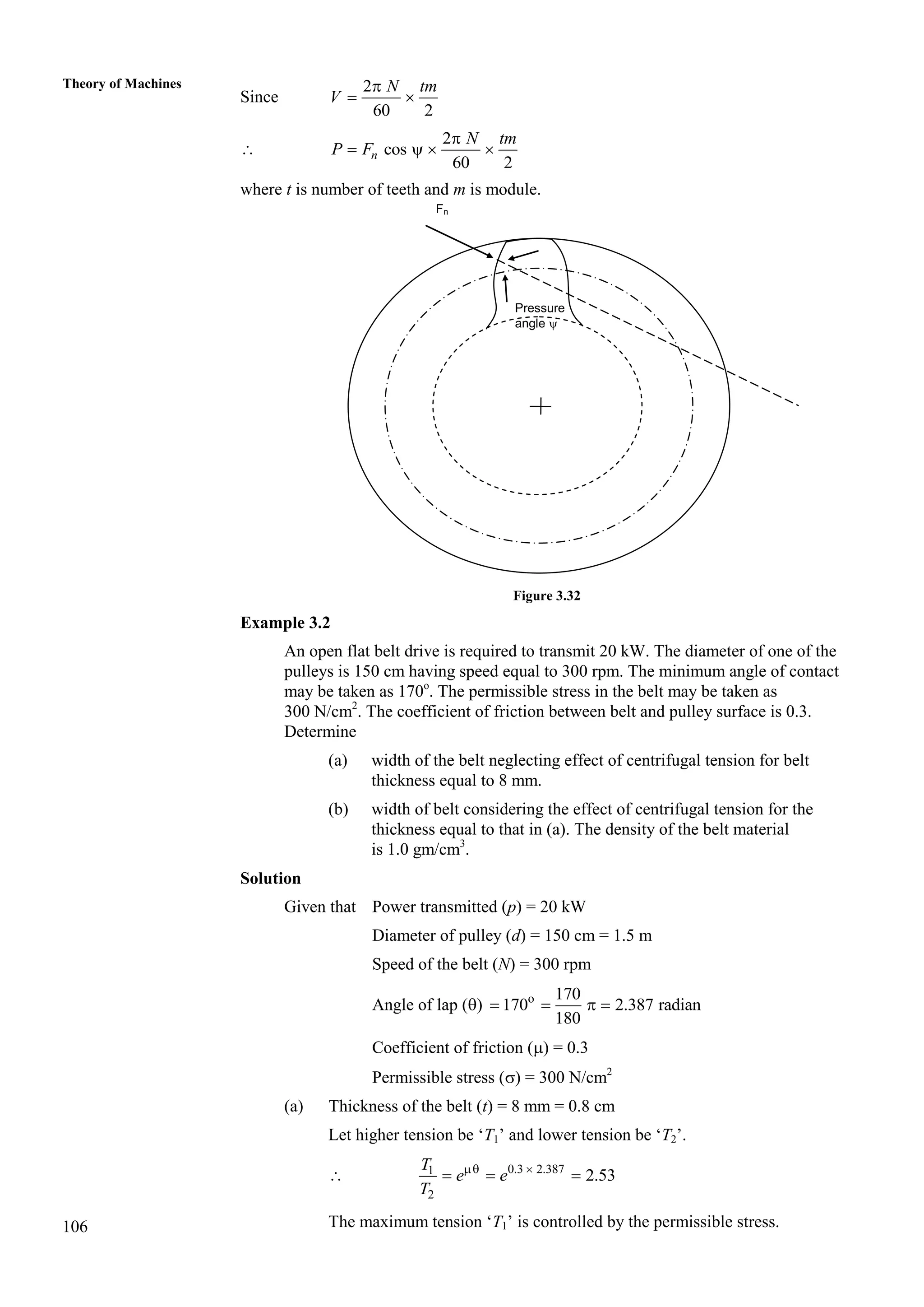
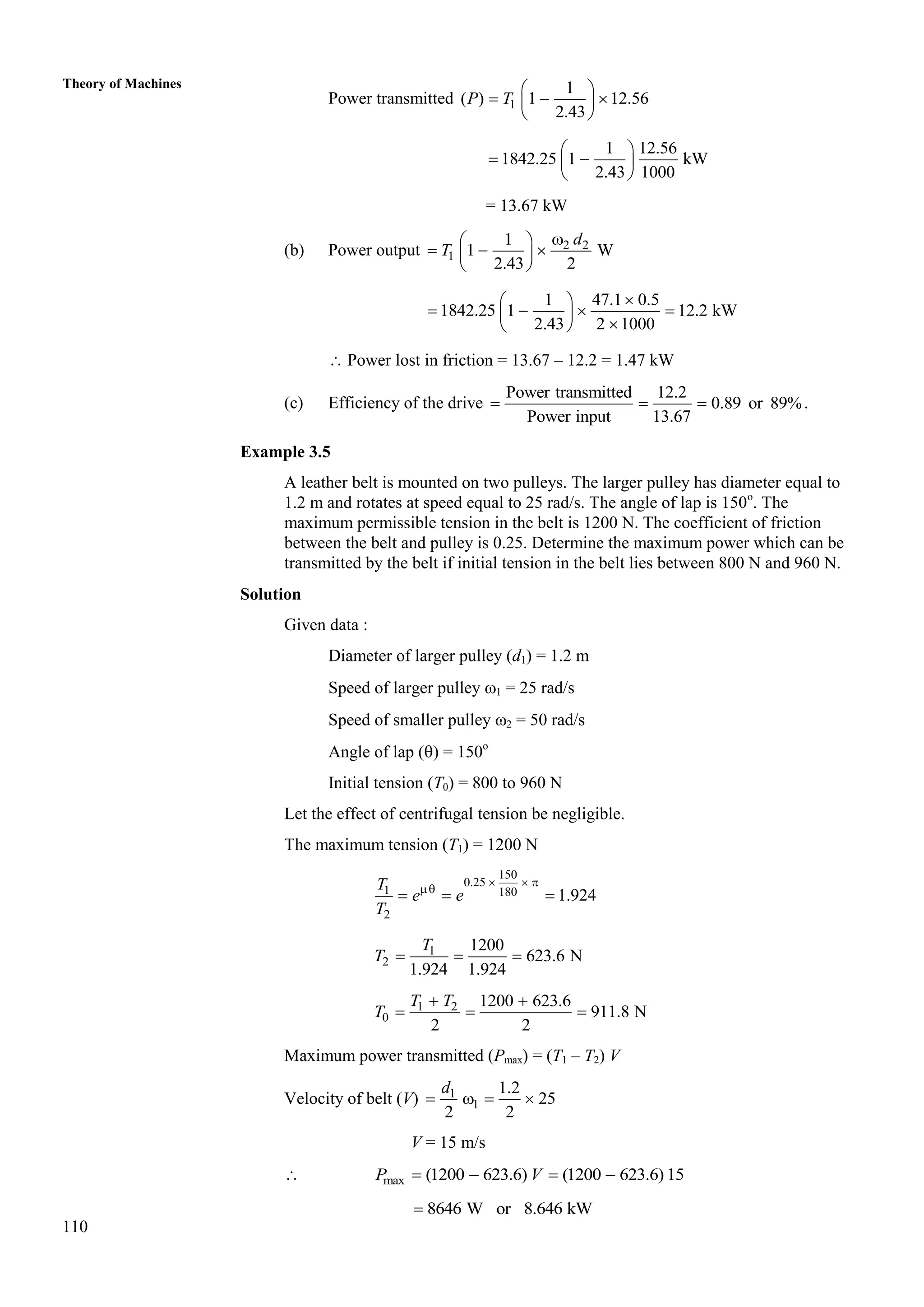


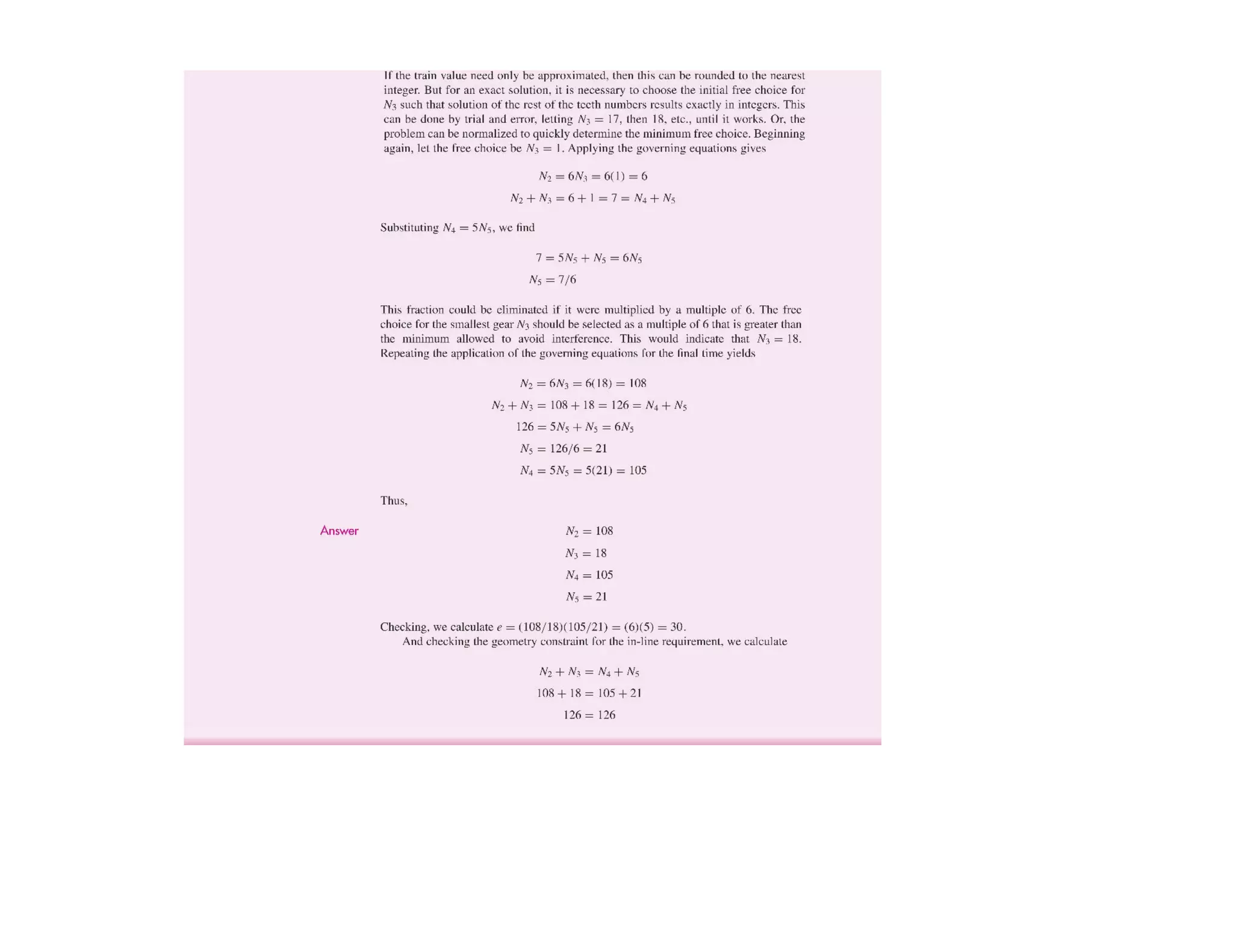


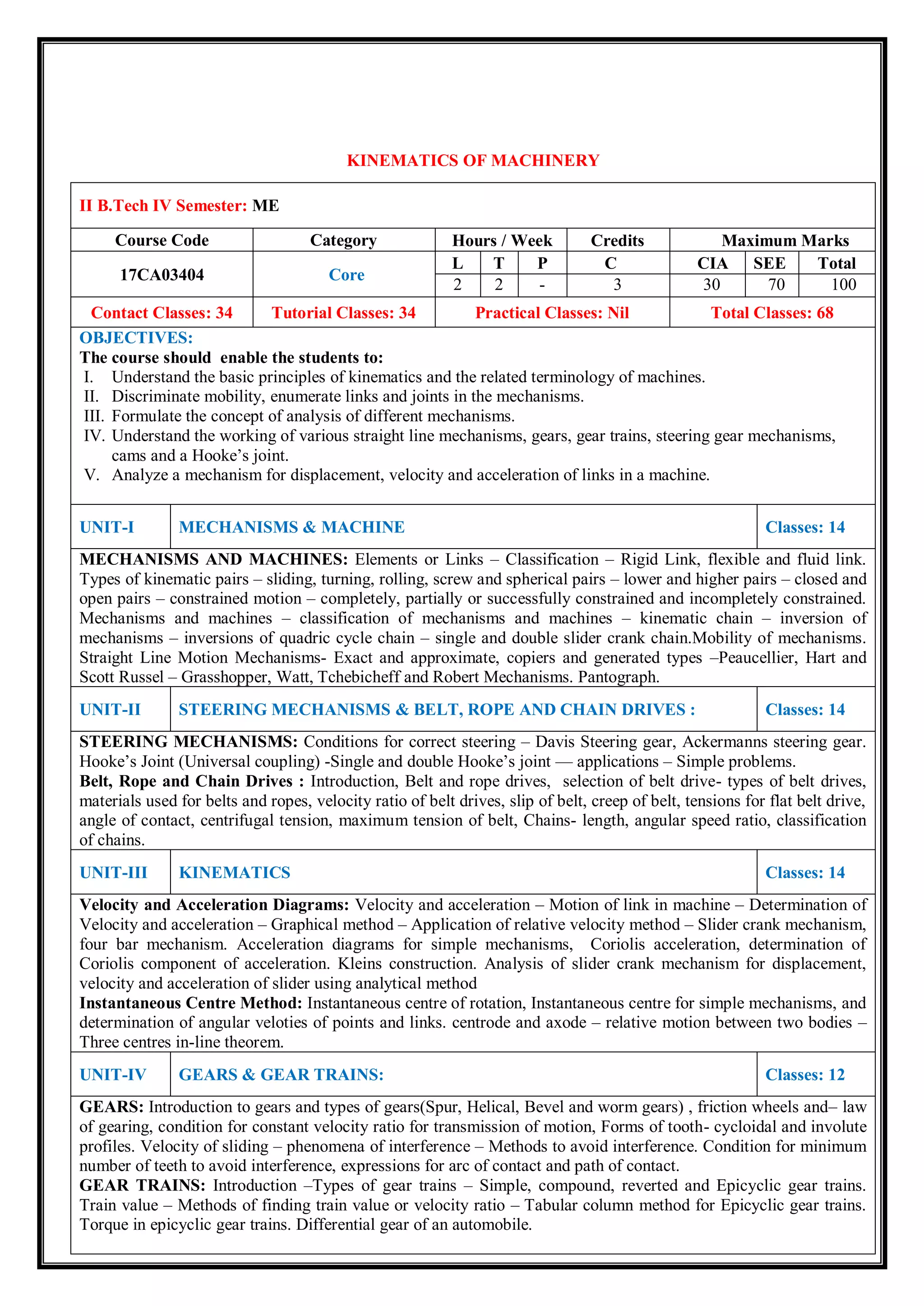
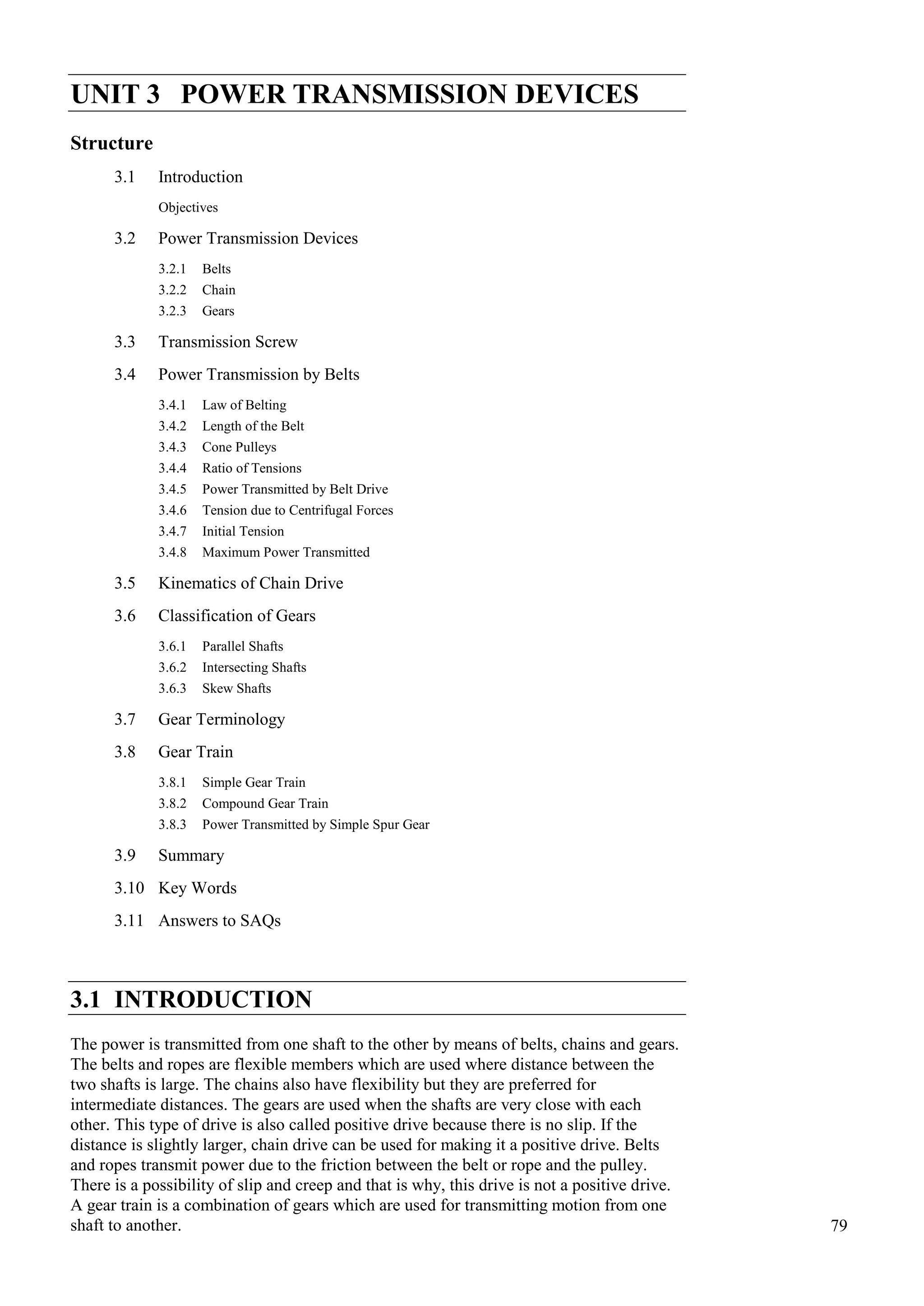
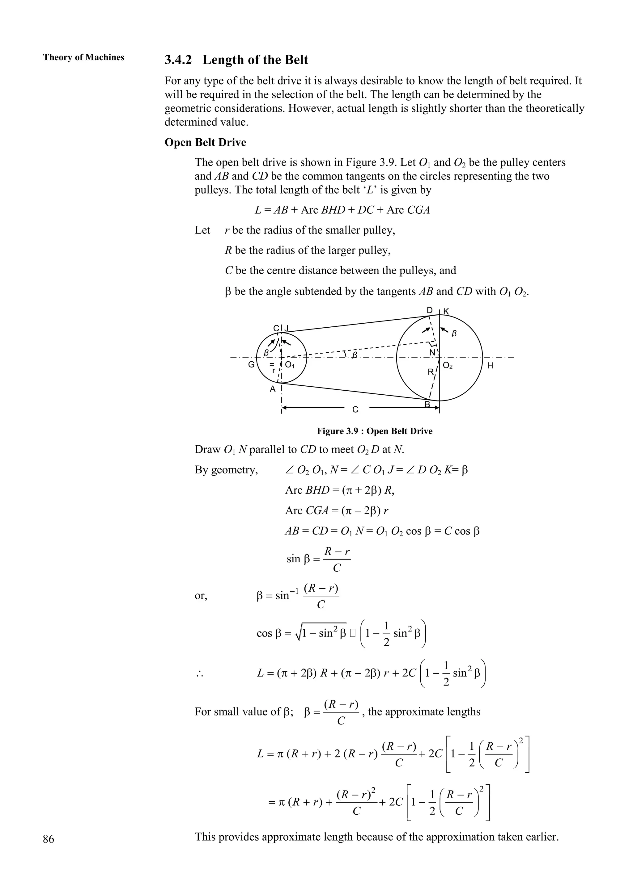
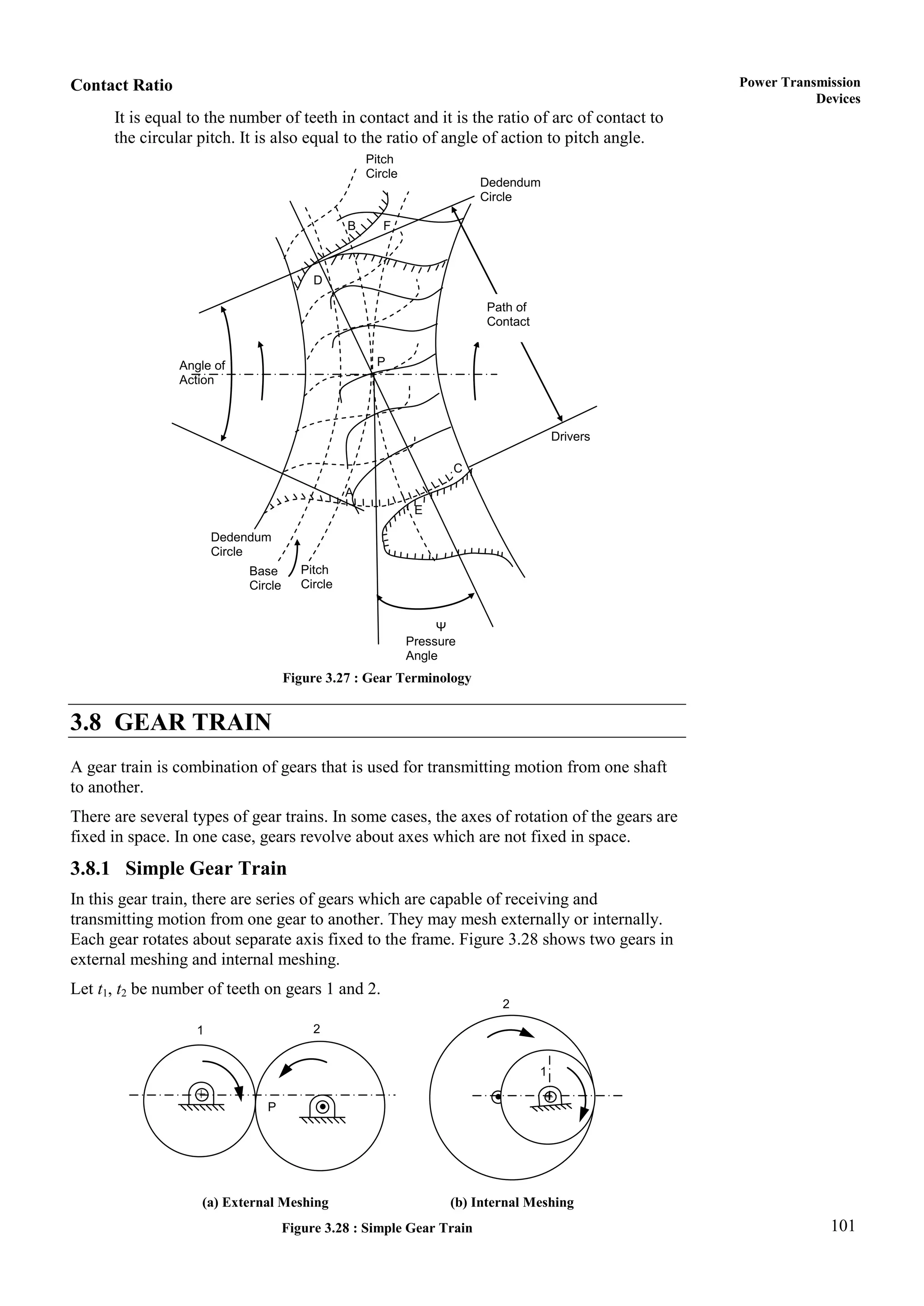
![FIGURE 3-13
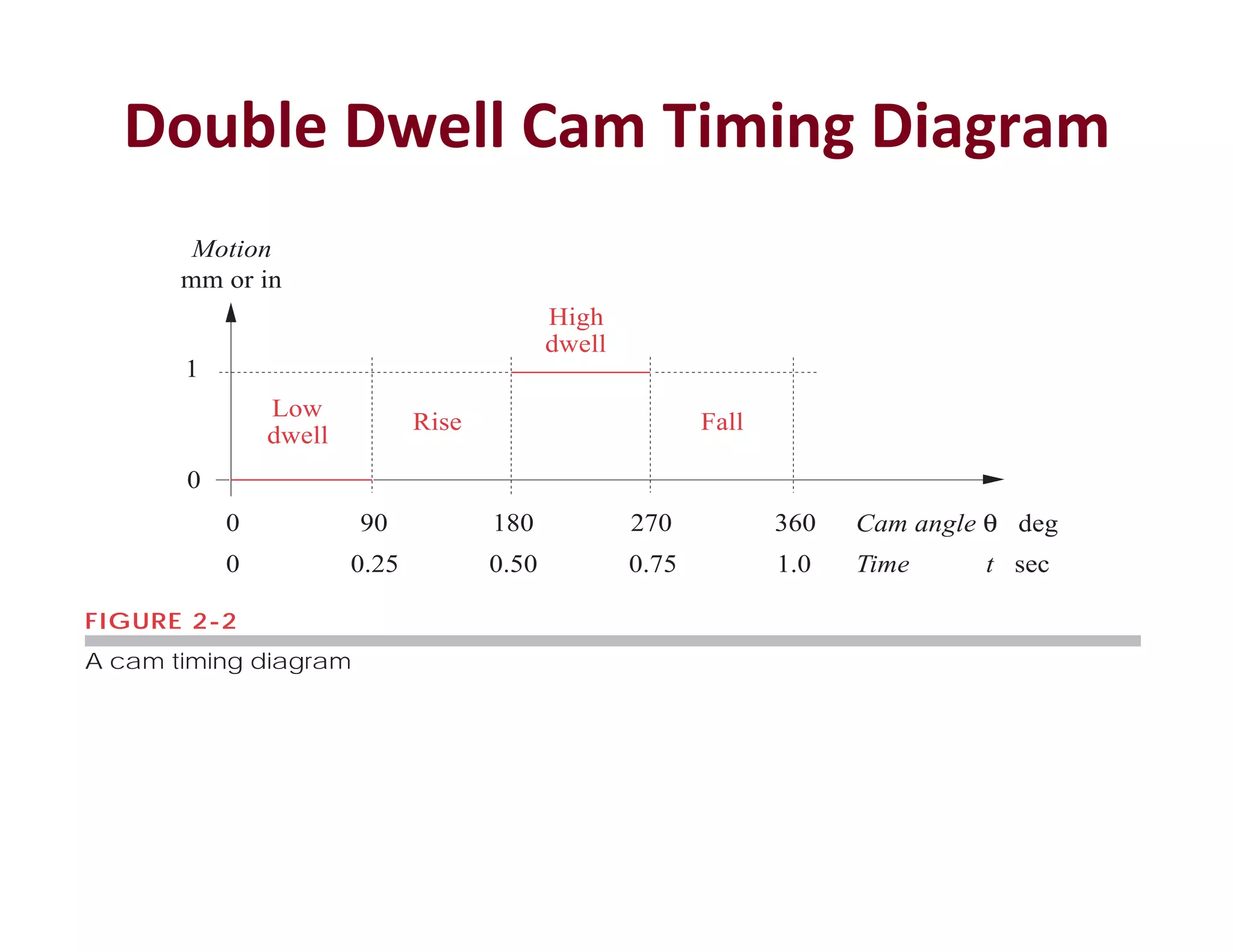
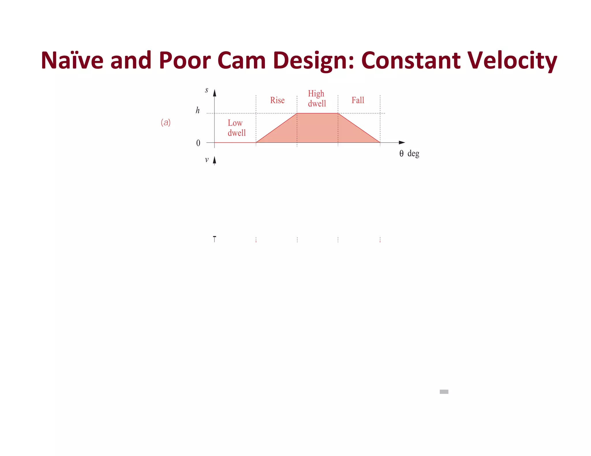
Minimum boundary conditions for the double-dwell case
(a)
(b)
(c)
(d )
h
0
s
v
0
a
0
j
0
Low
dwell
High
dwell
Rise Fall
deg
θ
deg
θ
deg
θ
deg
θ
β2
0 0
β1
β2
0 0
β1
β2
0 0
β1
β2
0 0
β1
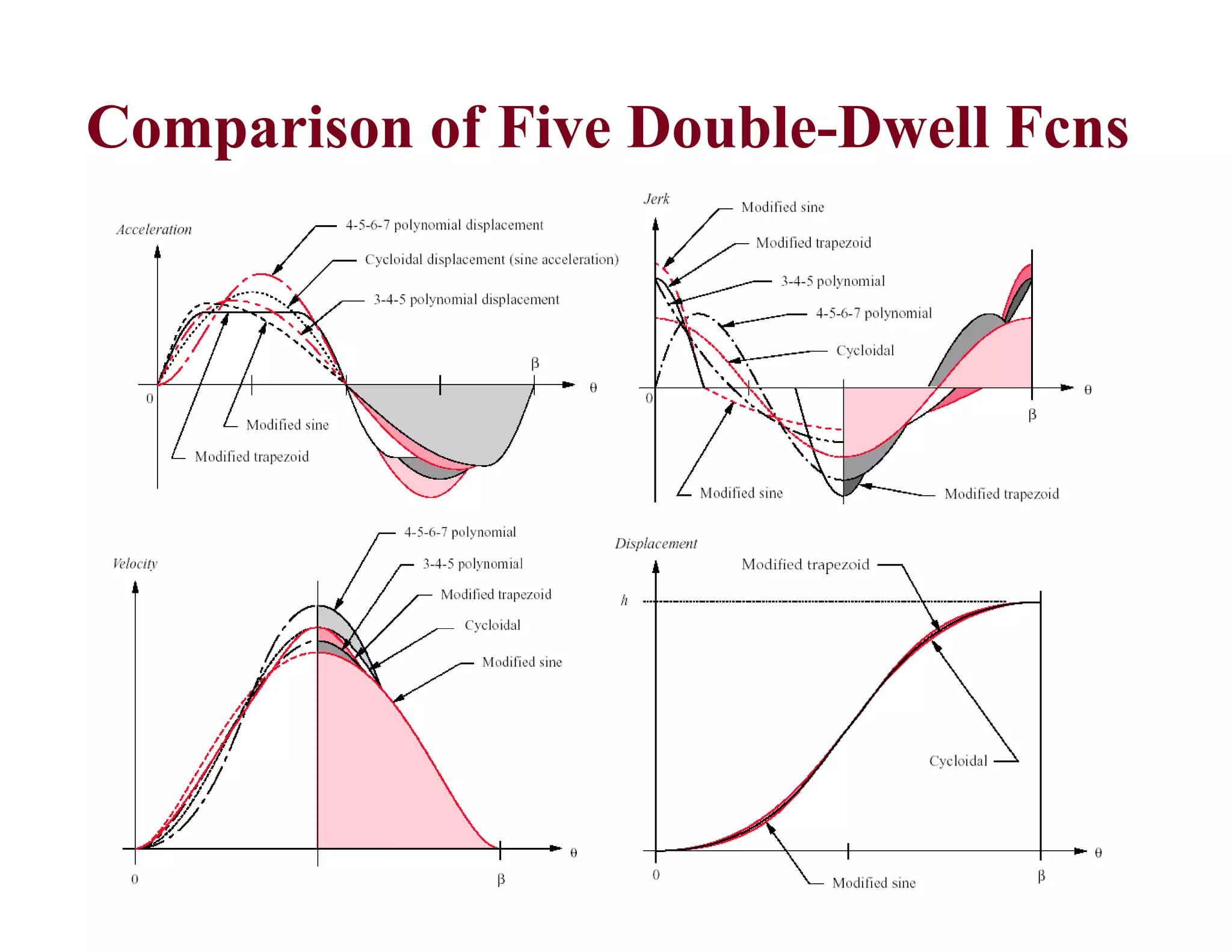
Polynomial Functions
s C C x C x C x C x C x C x C x
n
n
= + + + + + + + +
0 1 2
2
3
3
4
4
5
5
6
6
3 19
( . )
when then
(a)
when then
θ
θ β
= = = =
= = = =
0 0 0 0
0 0
1
; , ,
; , ,
s v a
s h v a
v C C C C C
= +
⎛
⎝
⎜
⎞
⎠
⎟ +
⎛
⎝
⎜
⎞
⎠
⎟ +
⎛
⎝
⎜
⎞
⎠
⎟ +
⎛
⎝
⎜
⎞
⎠
⎟
⎡
⎣
⎢
⎢
⎤
⎦
⎥
⎥
1
2 3 4 5
1 2 3
2
4
3
5
4
β
θ
β
θ
β
θ
β
θ
β
(d)
a C C C C
= +
⎛
⎝
⎜
⎞
⎠
⎟ +
⎛
⎝
⎜
⎞
⎠
⎟ +
⎛
⎝
⎜
⎞
⎠
⎟
⎡
⎣
⎢
⎢
⎤
⎦
⎥
⎥
1
2 6 12 20
2 2 3 4
2
5
3
β
θ
β
θ
β
θ
β
(e)
s C C C C C C
= +
⎛
⎝
⎜
⎞
⎠
⎟ +
⎛
⎝
⎜
⎞
⎠
⎟ +
⎛
⎝
⎜
⎞
⎠
⎟ +
⎛
⎝
⎜
⎞
⎠
⎟ +
⎛
⎝
⎜
⎞
⎠
⎟
0 1 2
2
3
3
4
4
5
5
θ
β
θ
β
θ
β
θ
β
θ
β
(c)
0 0 0
0
0
0
= + + +
=
C
C
(f)
0
1
0 0
0
1
1
= + + +
[ ]
=
β
C
C
(g)
0
1
0 0
0
2 2
2
= + + +
[ ]
=
β
C
C
(h)
h C C C
= + +
3 4 5 (i)
0
1
3 4 5
3 4 5
= + +
[ ]
β
C C C (j)
0
1
6 12 20
2 3 4 5
= + +
[ ]
β
C C C ( )
k
C h C h C h
3 4 5
10 15 6
= = − =
; ; (l)](https://image.slidesharecdn.com/komlecturenotes-210205072416/75/Kom-lecture-notes-158-2048.jpg)


![Wondershare Filmora 15.0.11 Crack for Mac Key Full Download [Latest] pptx](https://cdn.slidesharecdn.com/ss_thumbnails/software-251207184836-1d16ba16-thumbnail.jpg?width=640&height=640&fit=bounds)
![WinRAR Crack 7.13 Final Mac Keygen 2026 Download [Latest] Software.pptx](https://cdn.slidesharecdn.com/ss_thumbnails/software-251207185858-eb450678-thumbnail.jpg?width=640&height=640&fit=bounds)


