This document discusses kinematics and mechanisms. It defines kinematics as the branch of mechanics that describes the motion of bodies without considering the causes of motion. Kinematics examines displacement, velocity, and acceleration over time through graphical representations. Common mechanisms discussed include four-bar linkages, single slider-crank chains, and double slider-crank chains. Kinematic pairs constrain the motion between links and can be lower pairs with surface contact or higher pairs with point/line contact. Kinematic inversions occur when different links in a chain are fixed, resulting in different mechanisms.
Introduction to the presenter and overview of Kinematics (motion without forces) and Dynamics (forces affecting motion) in machines.
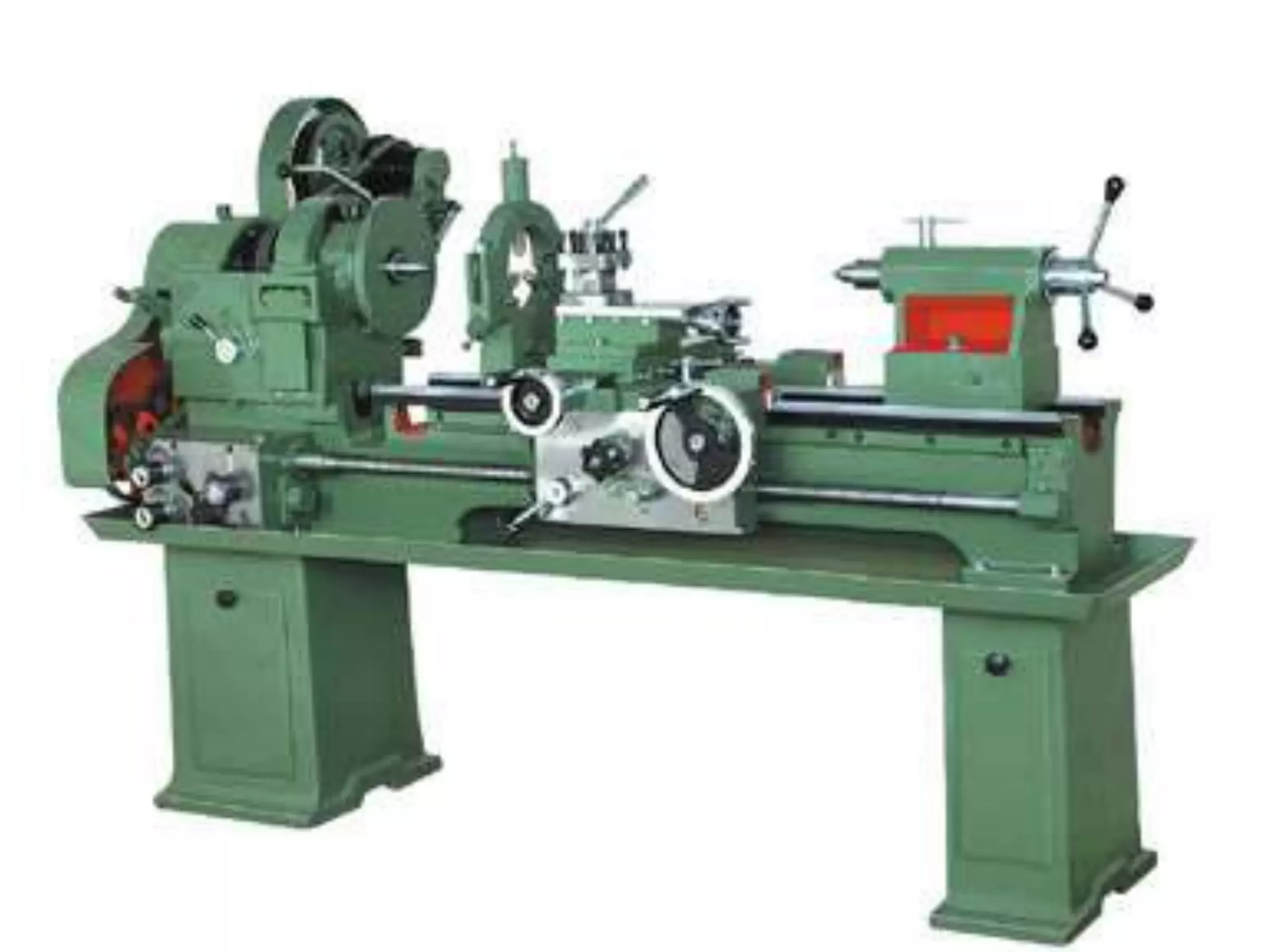
Definition of a machine as a device converting energy into work.
Explains mechanisms, transforming forces/movement, types including gears, belt drives, cams, and distinctions of planar vs spatial mechanisms.
Defines kinematic pairs based on bonding and types, including sliding, turning, rolling, screw, spherical, and distinctions between lower and higher pairs.
Kinematic chains formed by linking kinematic pairs with details on different joint types and classifications like four-bar chains and slider crank chains.
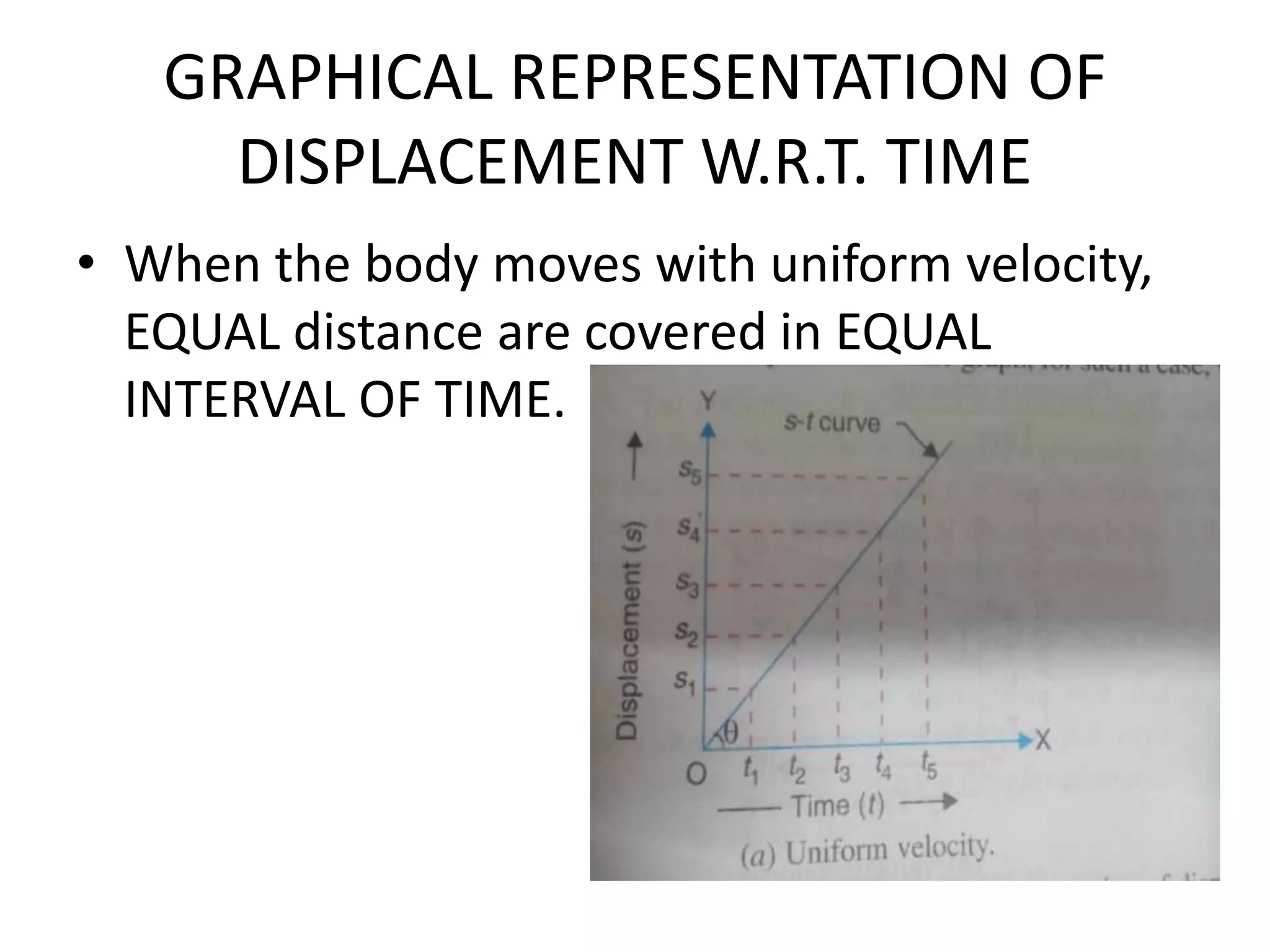
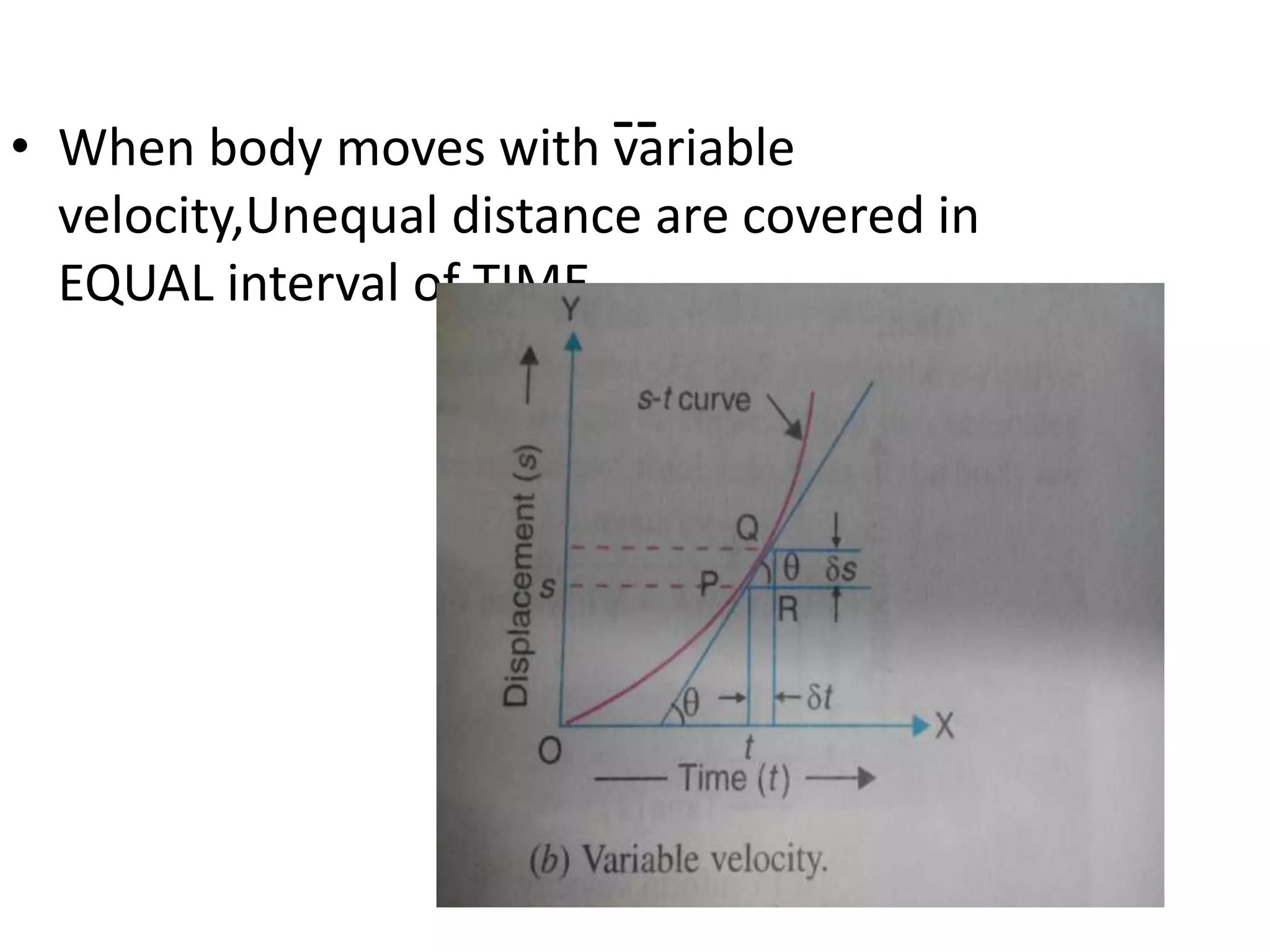
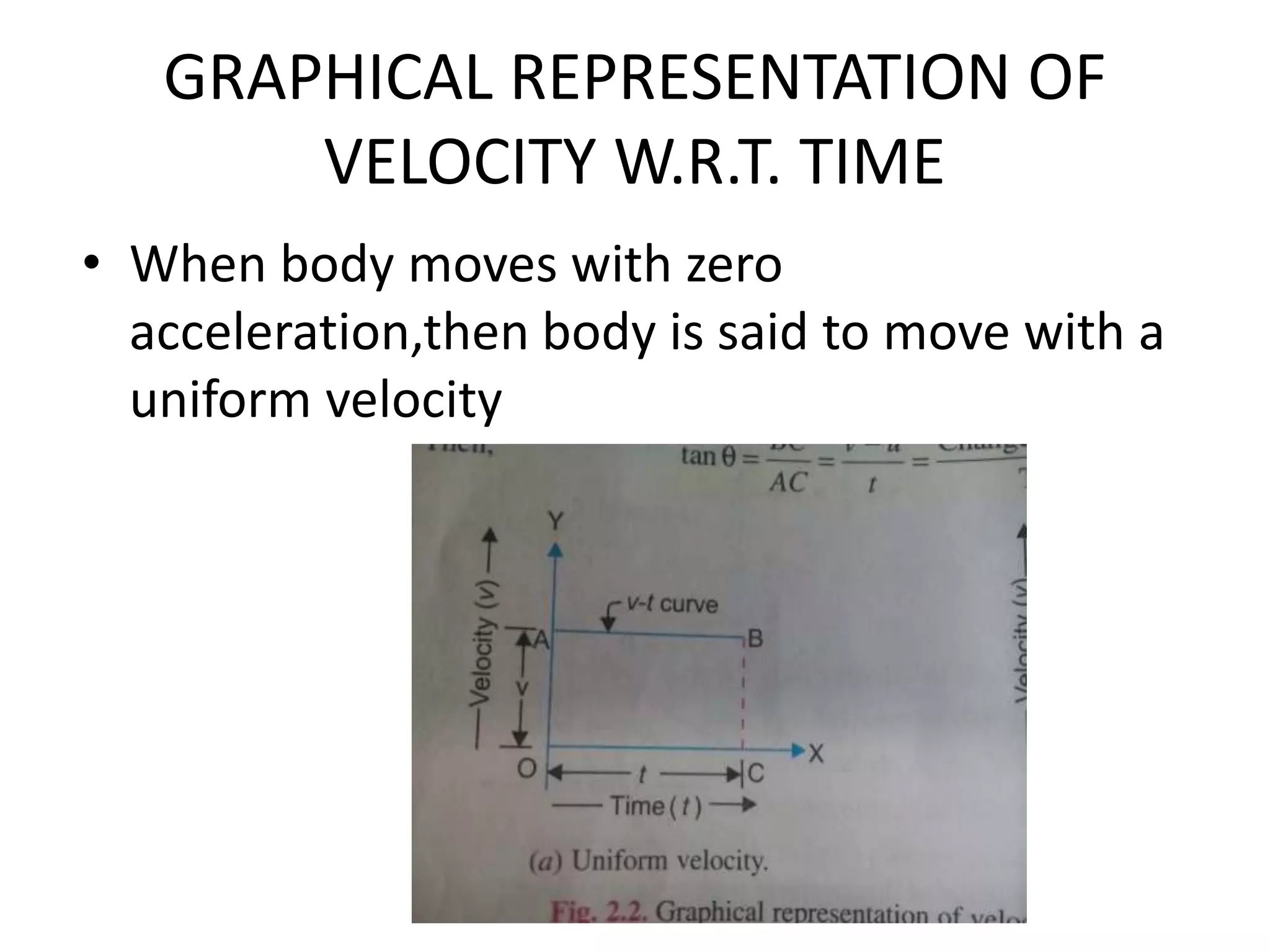
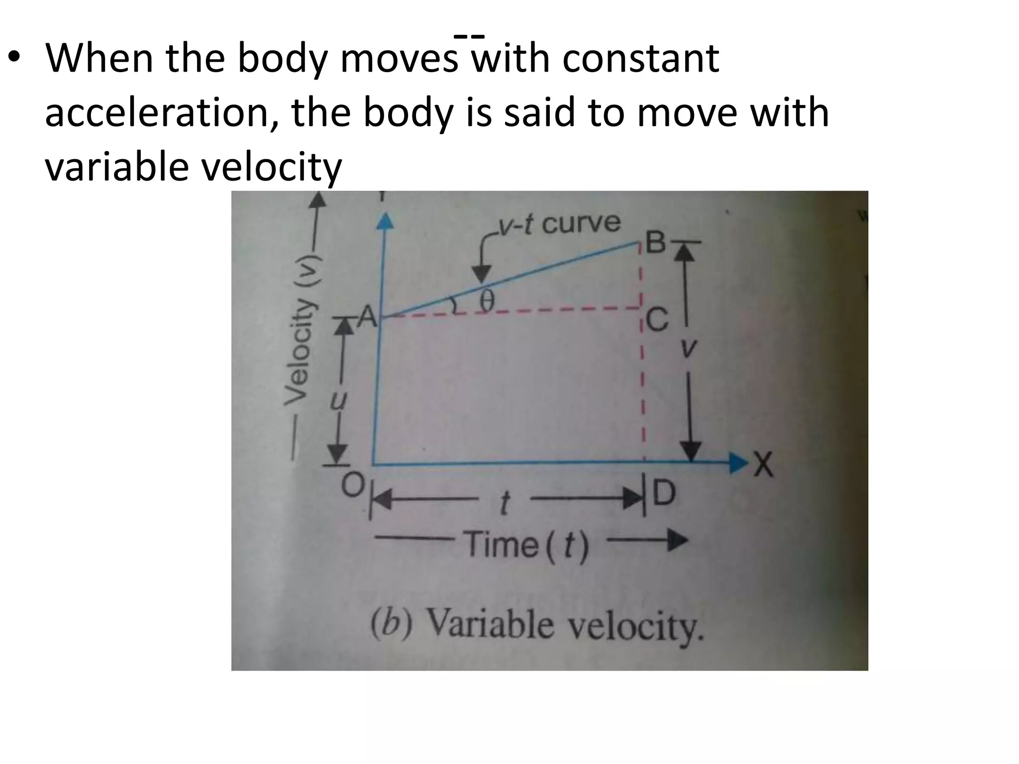
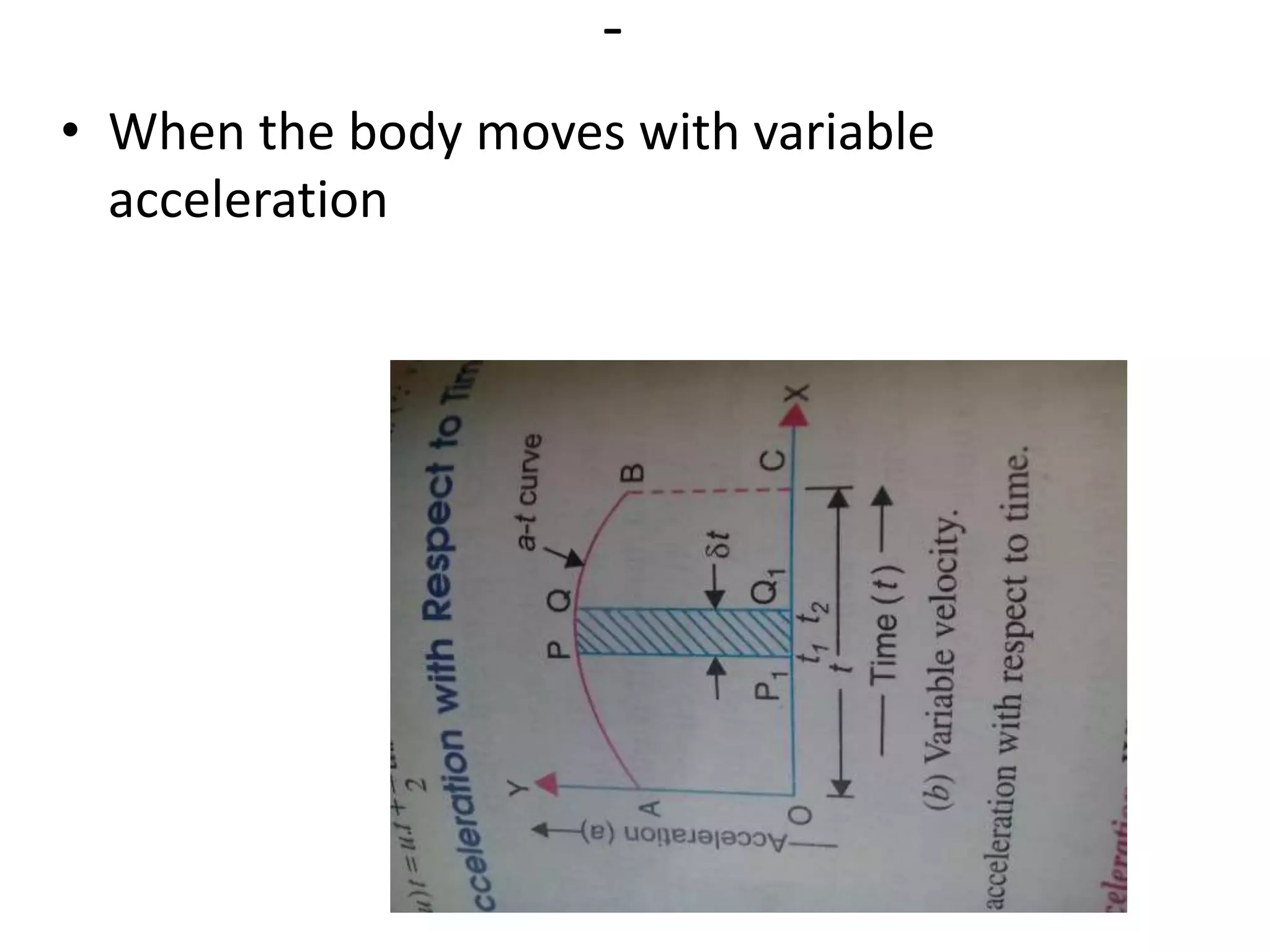
Definition of kinematics and graphical representation of displacement, velocity, and acceleration over time, emphasizing uniform and variable trends.
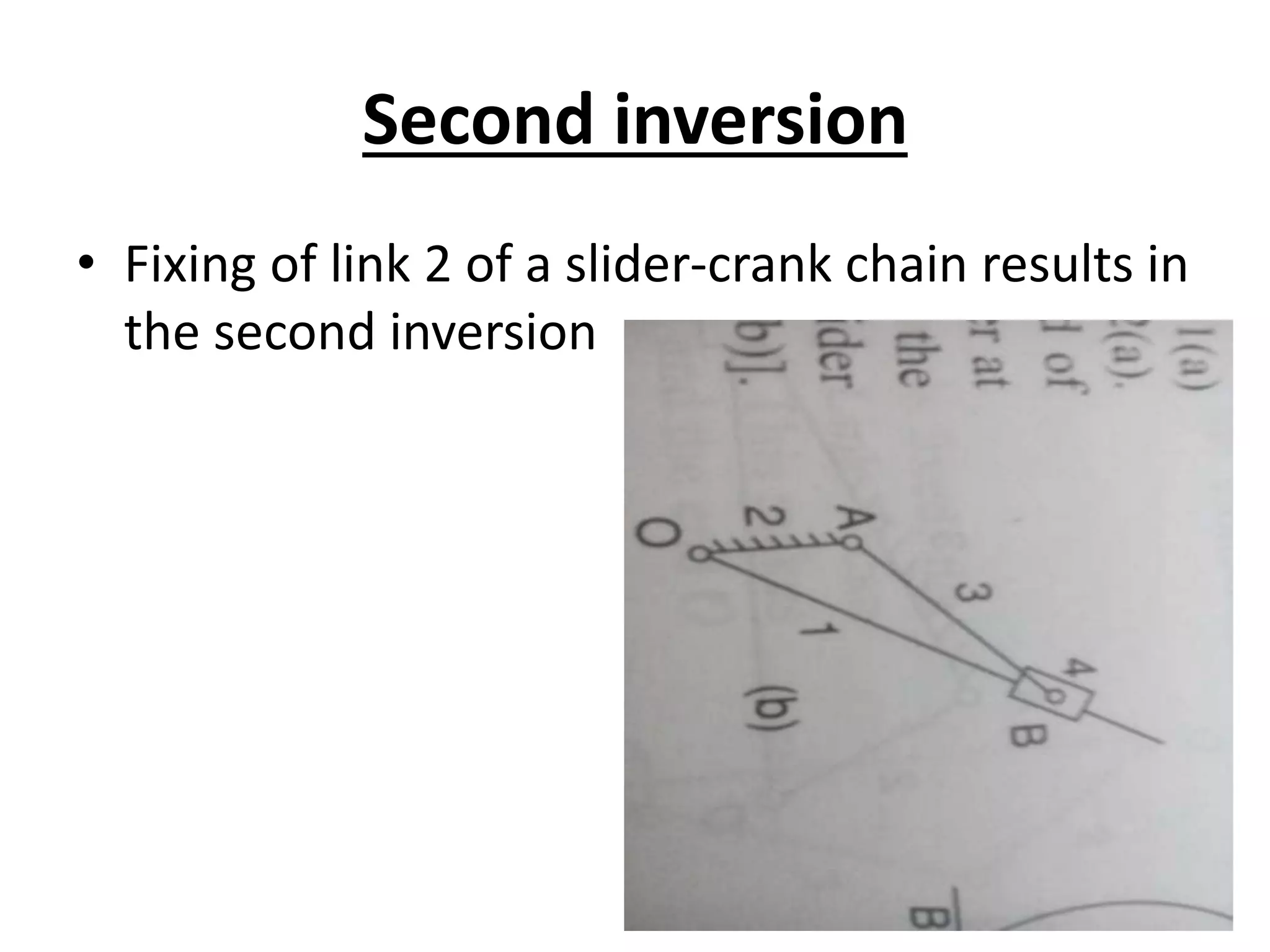
Explanation of kinematic inversions, the different mechanisms formed by fixing links in a chain, with examples of the first and second inversions.
Name : SurendrasingB. Bhil
Branch : Mechanical
Div. : M
En. No : 140170119002
Subject : Kinetics of Machines
2.
KINEMATICS
• It isthat branch of theory of machine which
deals with relative motion between the
various parts of machines.
• Kinematics describes the motion of points ,
bodies without consideration of the causes of
motion.
3.
DYNAMICS
• It isthat branch of theory of machine which
deals with the force and their effects, while
acting upon the machine part in motion.
4.
MACHINE
• It isa device which recevies energy in some
avilable form and utilizes it to some particular
work.
• A machine is a tool containing one or more
parts that uses energy to perform an intened
Action.
7.
MECHANISM
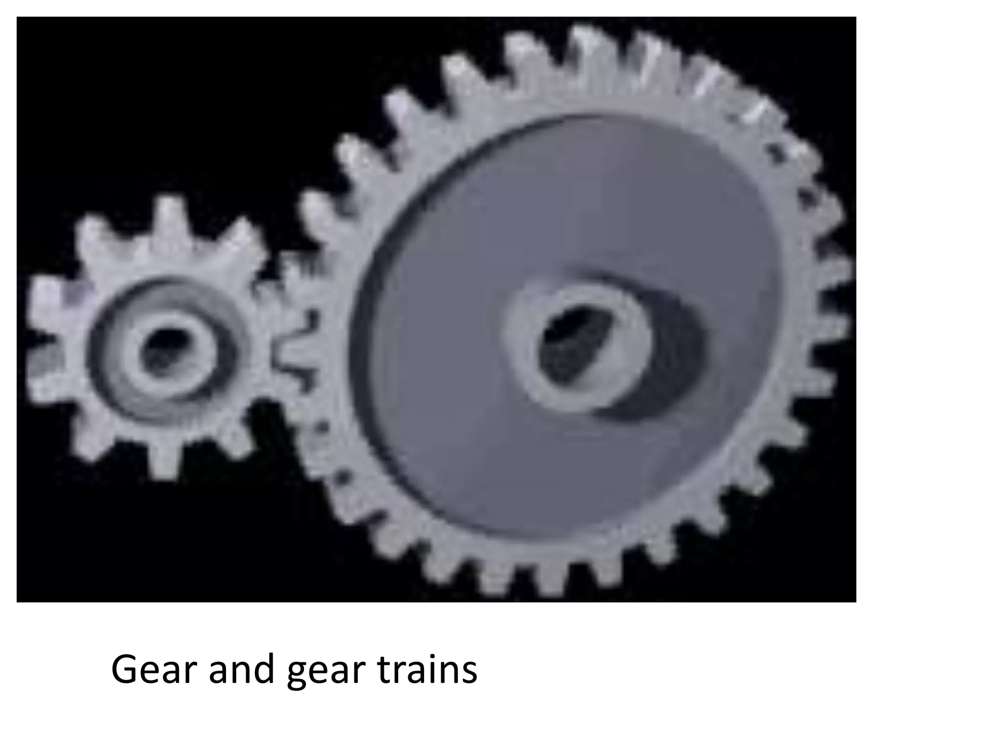
• It isa device designed to transform input
forces and movement into desired set of
output forces and movement.
• EXM: 1.Gear and gear trains
• 2.Belt and chain drive
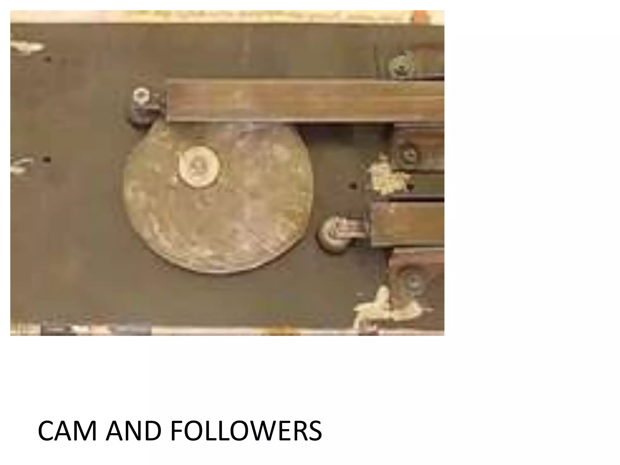
• 3.Cam and followers
• 4.Breaks and clutches
MECHANISM
• TYPES
• 1.Planarmechanism
• 2.Spatial mechanism
• Planar mechanism: it is a mechanism in which all
of the relative motion of the rigid bodies are in
one plane or in parallel plane.
• It is a mechanical system that is constrained so the
trajectories of stomachs in all the bodies of the
system lie on aeroplanes parallel to a ground
plane.
13.
SPATIAL MECHANISM
• Allthe relative motion of the rigid bodies are
not in a same plane or in different planes.
• It is mechanical system that has at least one
body that moves in a way that its point
trajectories are general space curves.
15.
Kinematic pair
• Thetwo link or element of a machine, when in contact with
each other, are said to form a pair.If relative motion between
then is completely or succefully contrained, the pair is knows
as kinematic pair.
Classification of kinematic pair
16.
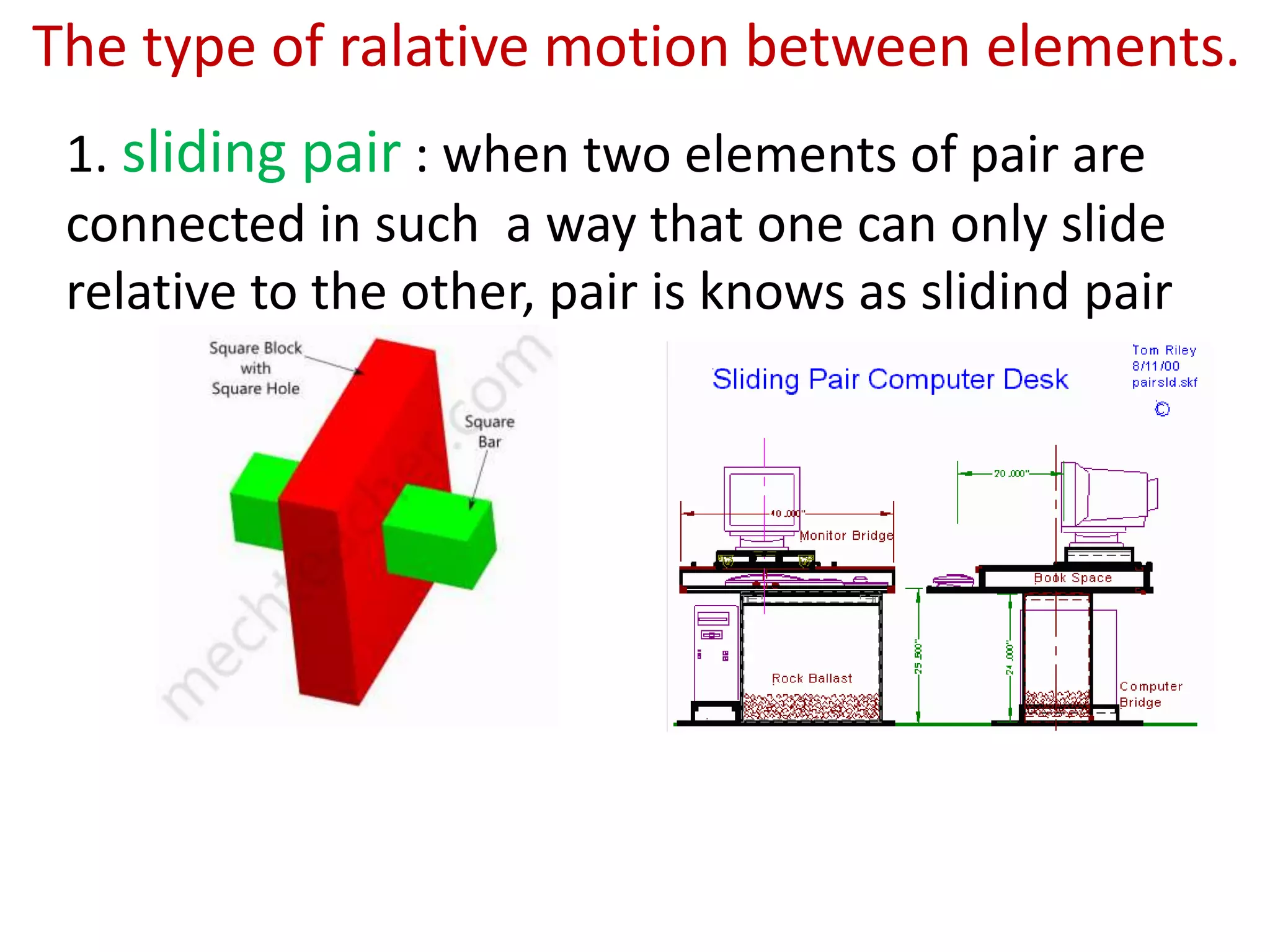
1. sliding pair: when two elements of pair are
connected in such a way that one can only slide
relative to the other, pair is knows as slidind pair
The type of ralative motion between elements.
17.
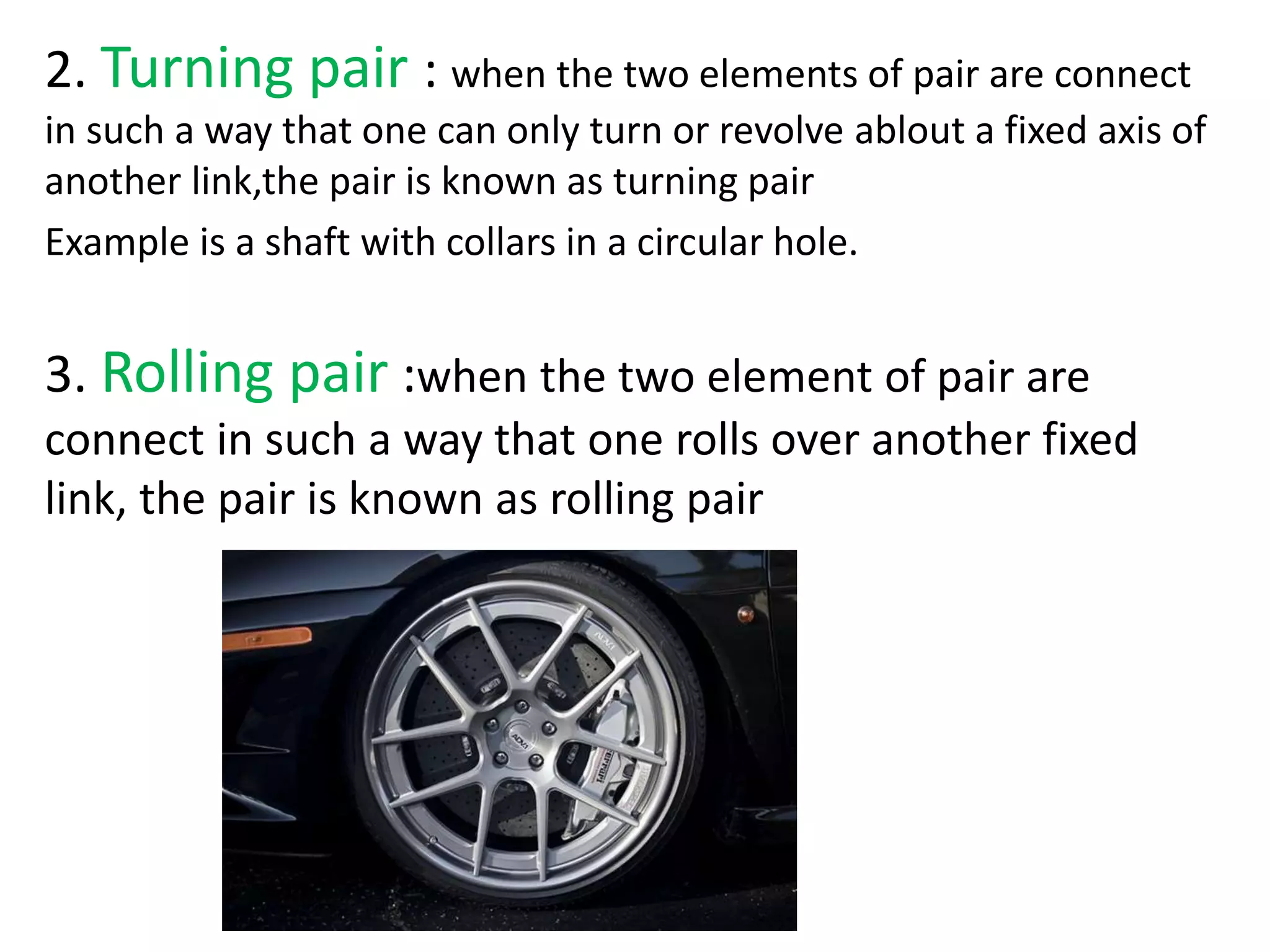
2. Turning pair: when the two elements of pair are connect
in such a way that one can only turn or revolve ablout a fixed axis of
another link,the pair is known as turning pair
Example is a shaft with collars in a circular hole.
3. Rolling pair :when the two element of pair are
connect in such a way that one rolls over another fixed
link, the pair is known as rolling pair
18.
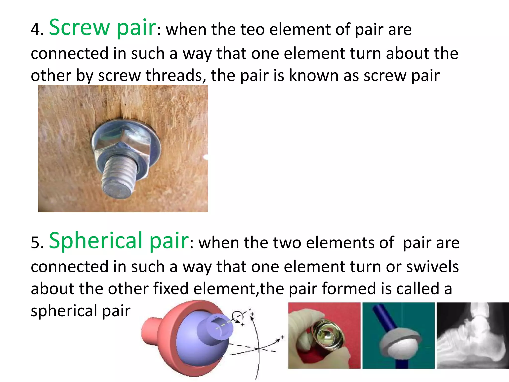
4. Screw pair:when the teo element of pair are
connected in such a way that one element turn about the
other by screw threads, the pair is known as screw pair
5. Spherical pair: when the two elements of pair are
connected in such a way that one element turn or swivels
about the other fixed element,the pair formed is called a
spherical pair
19.
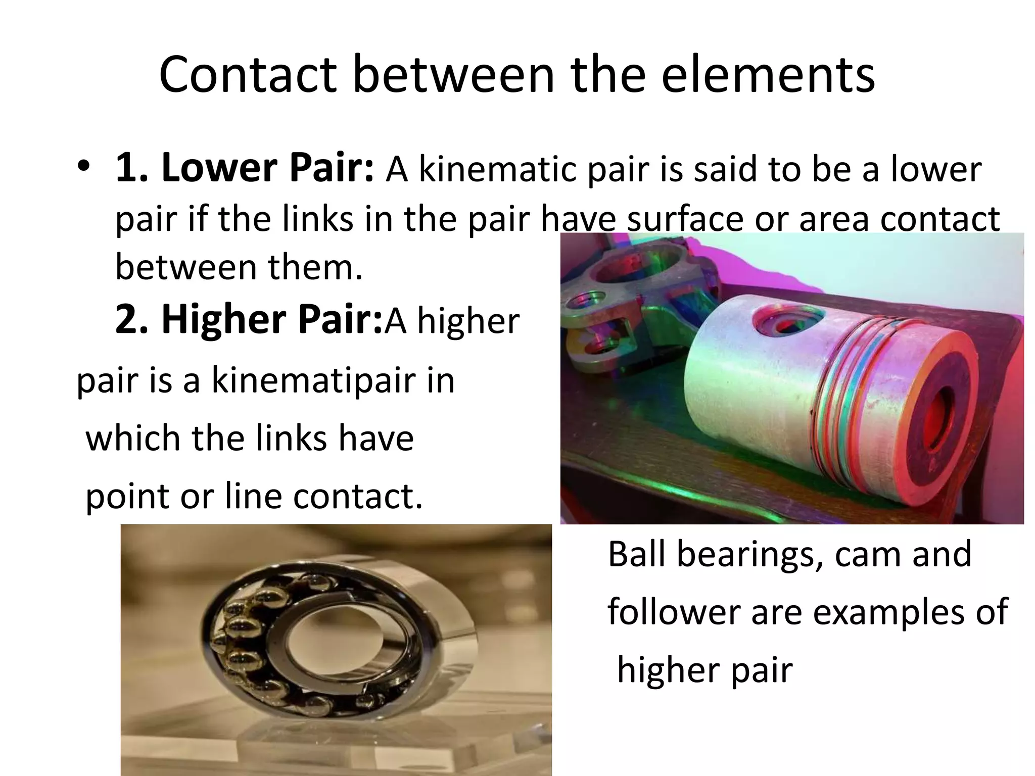
Contact between theelements
• 1. Lower Pair: A kinematic pair is said to be a lower
pair if the links in the pair have surface or area contact
between them.
2. Higher Pair:A higher
pair is a kinematipair in
which the links have
point or line contact.
Ball bearings, cam and
follower are examples of
higher pair
20.
The type ofclosure
• 1. Self Closed Pair: A pair is said to be self closed
if the links in the pair have direct mechanical
contact, even without the application of external
force.
• 2. Force Closed Pair: A kinematic pair is said to be
force closed if the links in the pair are kept in
contact by the application of external forces. A
good example of this type of pair is ball and roller
bearings.
21.
Kinetic chain
-> Whenthe kinematic pairs are couple such a
way that last link is joined to the first link to
transmit definite motion, it is called a kinematic
chain
Types of joint in chain
1. Binary joint
2. Ternary joint
3. Quaternary joint
22.
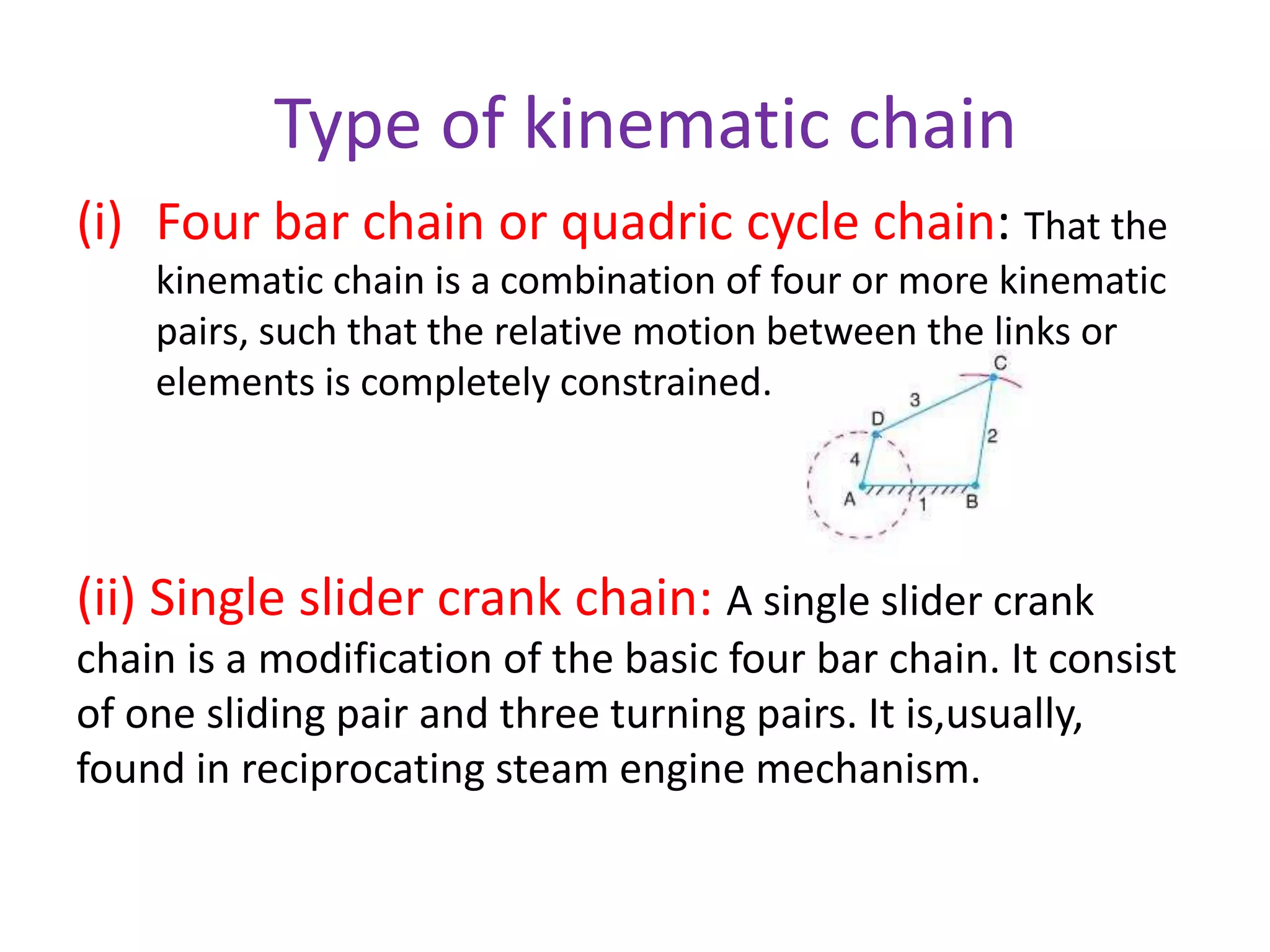
Type of kinematicchain
(i) Four bar chain or quadric cycle chain: That the
kinematic chain is a combination of four or more kinematic
pairs, such that the relative motion between the links or
elements is completely constrained.
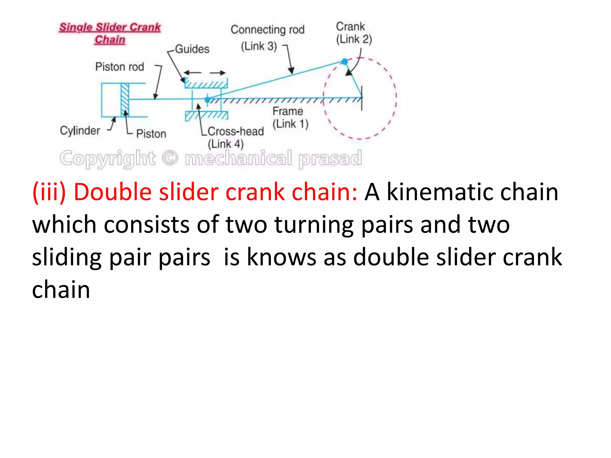
(ii) Single slider crank chain: A single slider crank
chain is a modification of the basic four bar chain. It consist
of one sliding pair and three turning pairs. It is,usually,
found in reciprocating steam engine mechanism.
23.
(iii) Double slidercrank chain: A kinematic chain
which consists of two turning pairs and two
sliding pair pairs is knows as double slider crank
chain
Kinematic inversion
• Differentmechanisms obtained by fixing
different links of a kinematic chain are known
as its inversion.
• A slider-crank chain has the following
inversion
34.
First inversion
• Thisinversion is obtained
when link 1 is fixed and link
2 &4 are made the crank and
Slider respectively