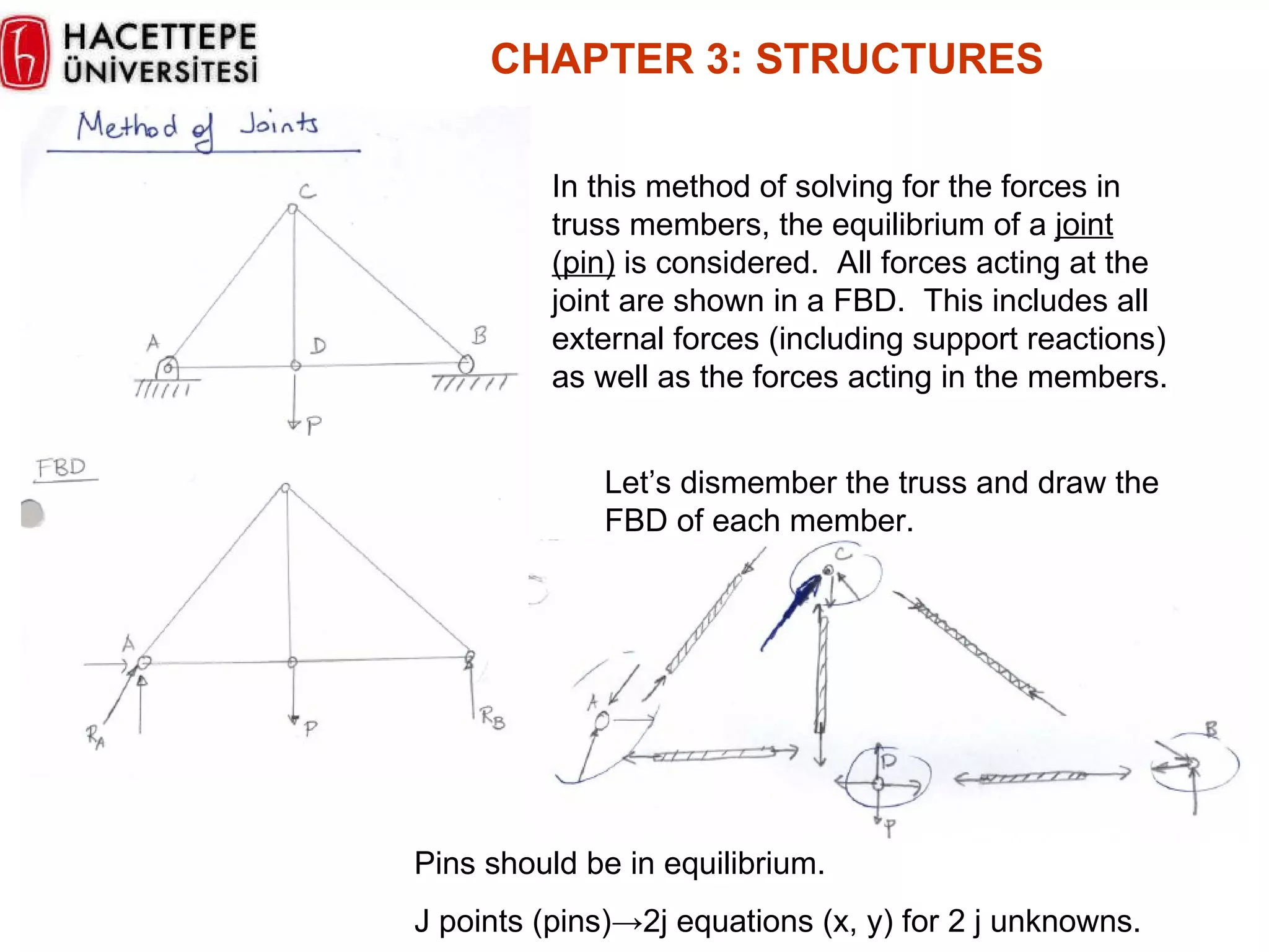
The document discusses different types of structures and methods for analyzing trusses. Trusses are structures made of straight members connected at joints. Two common methods for analyzing trusses are the method of joints and method of sections. The method of joints involves drawing force diagrams at each joint and applying equilibrium equations. The method of sections involves cutting a truss and analyzing one side of the cut section. Zero-force members, which carry no load, can be identified and removed to simplify analysis.
In this document
Powered by AI
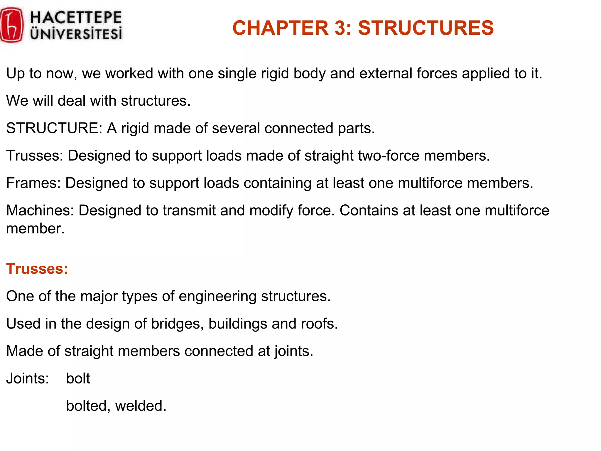
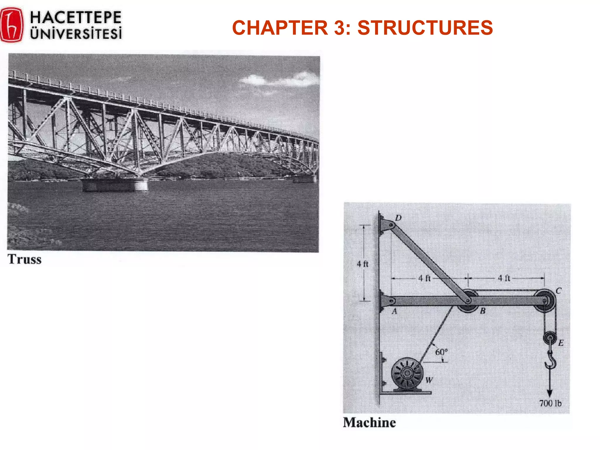
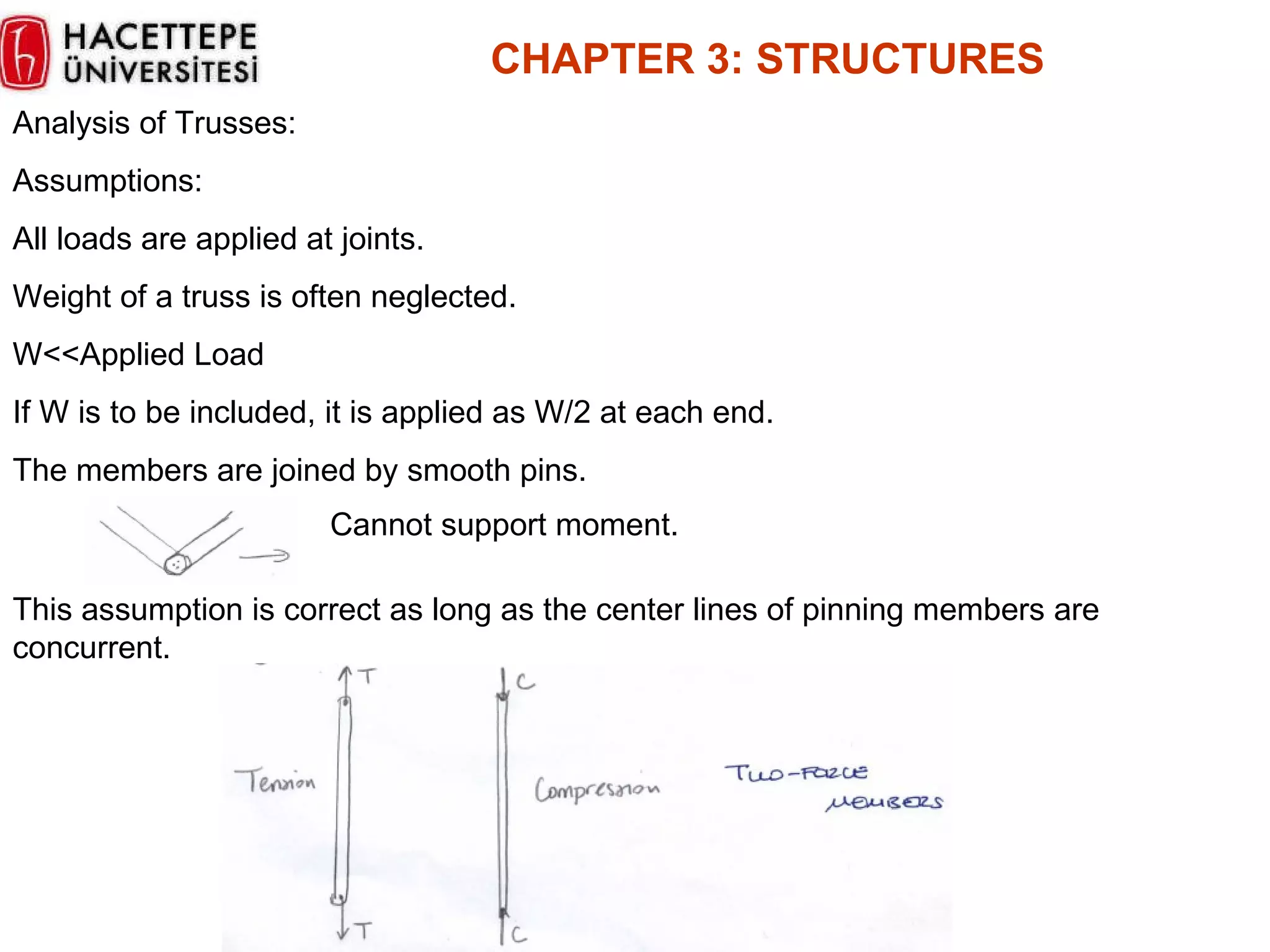
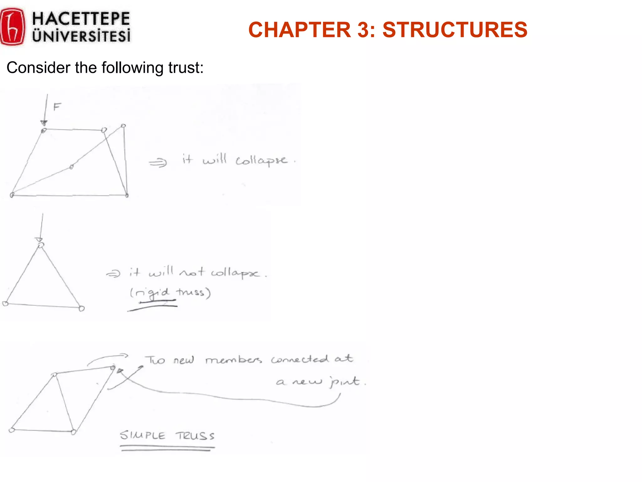
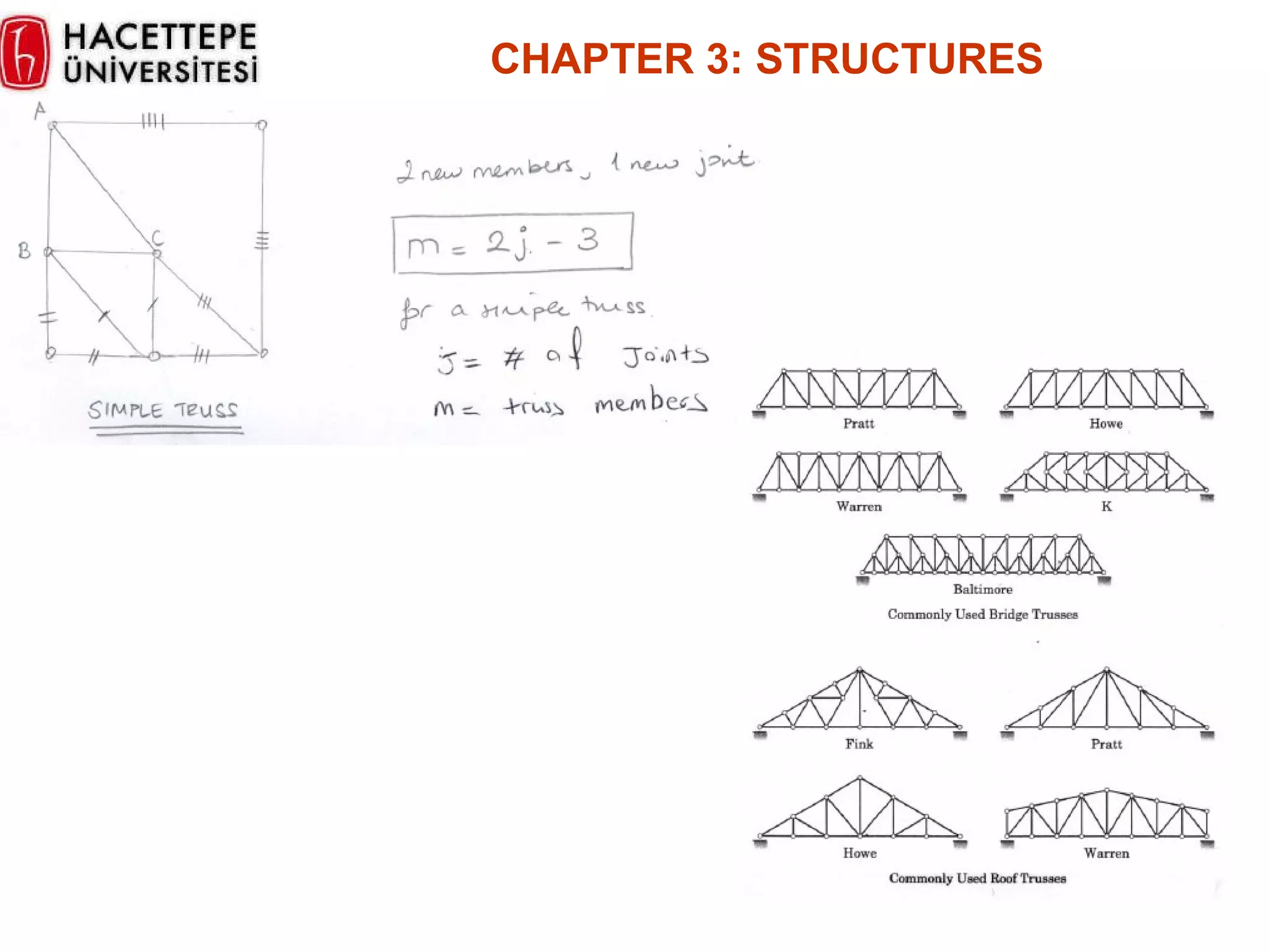
Introduction to structures, types (trusses, frames, machines), and analytical assumptions for trusses.
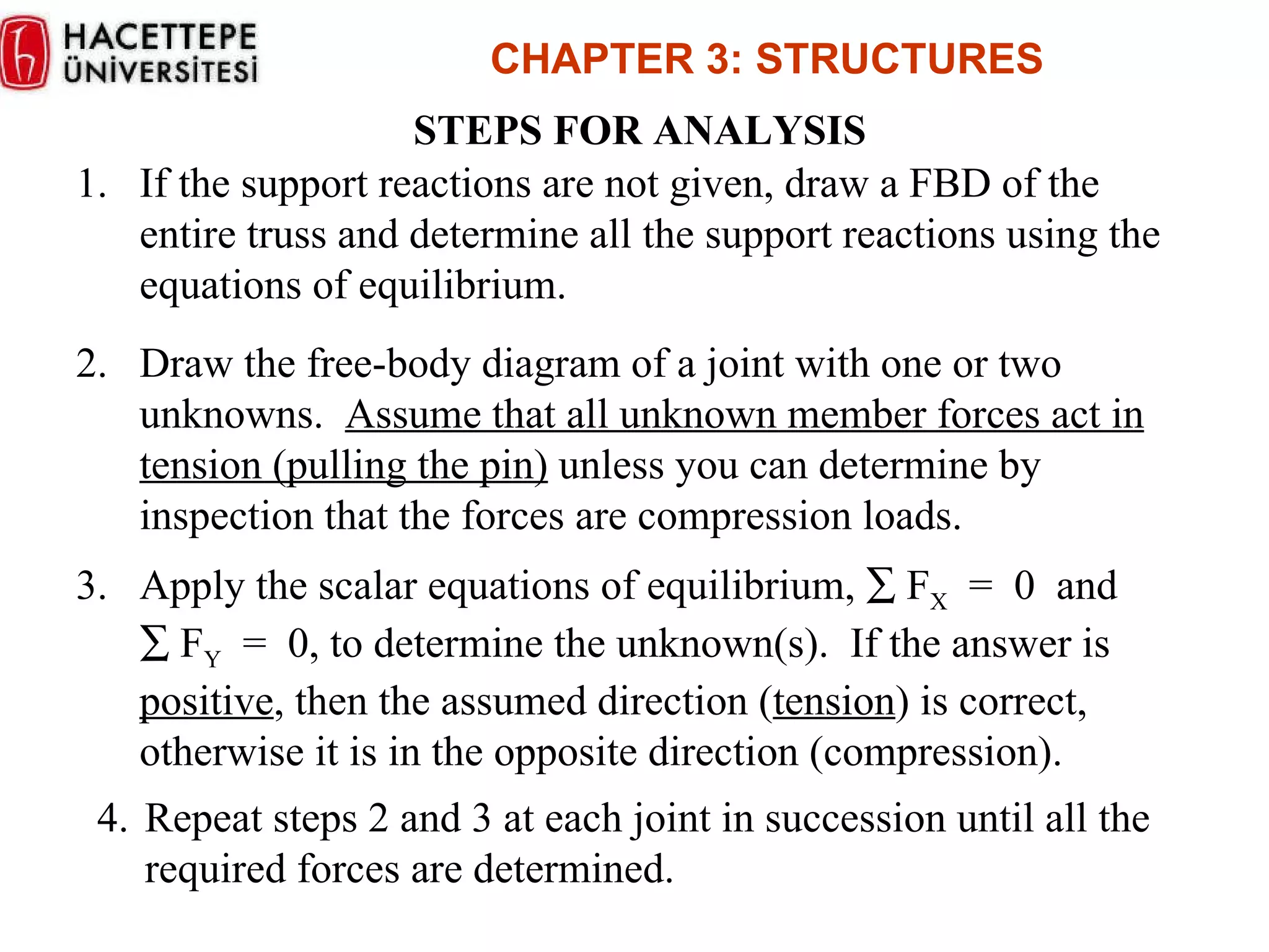
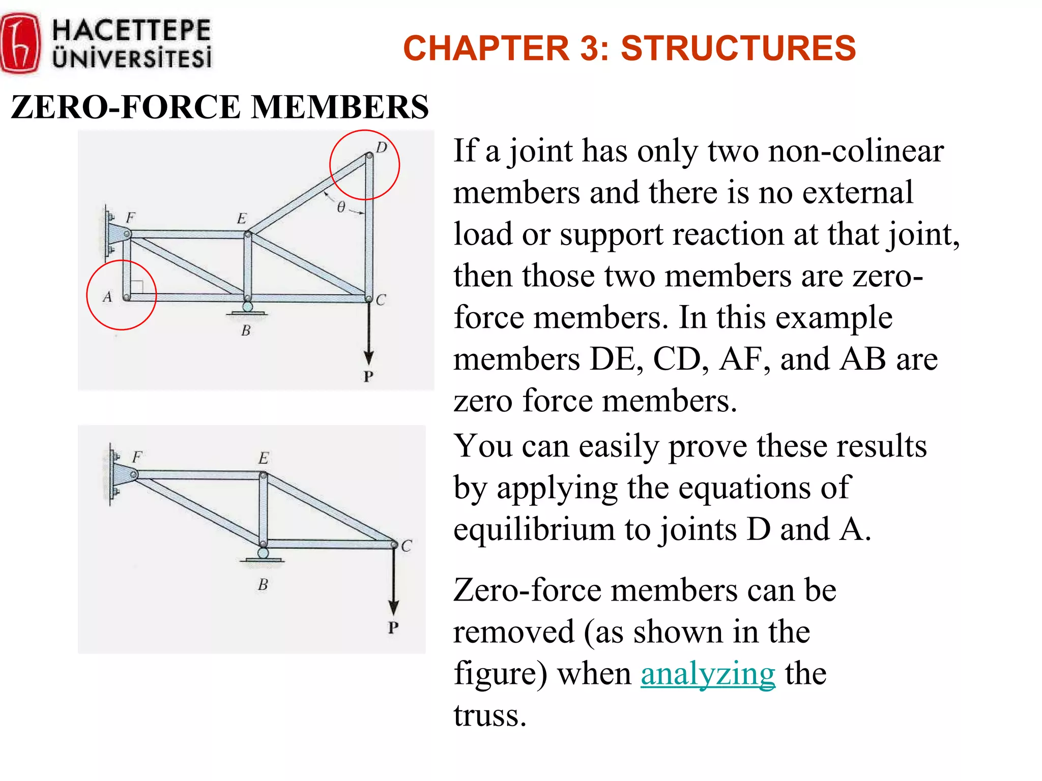
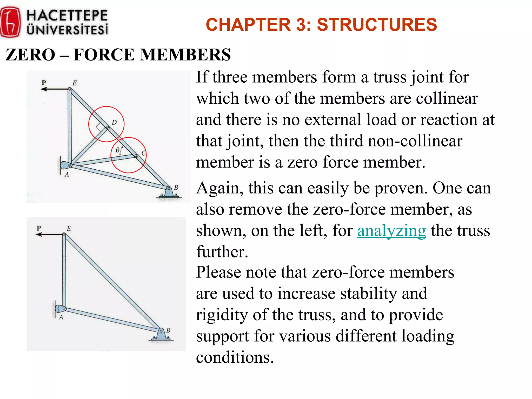
Steps for truss analysis using free-body diagrams and identifying zero-force members for efficient analysis.
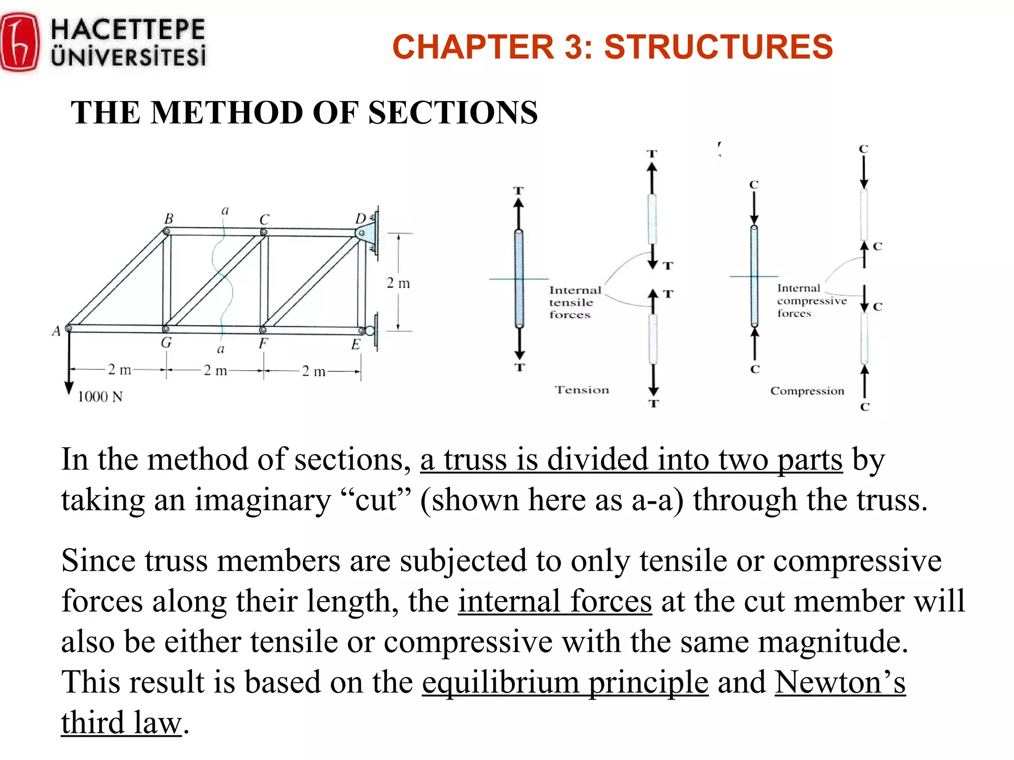
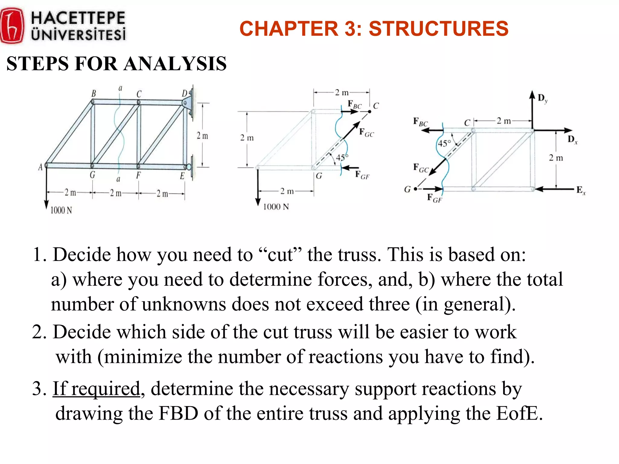
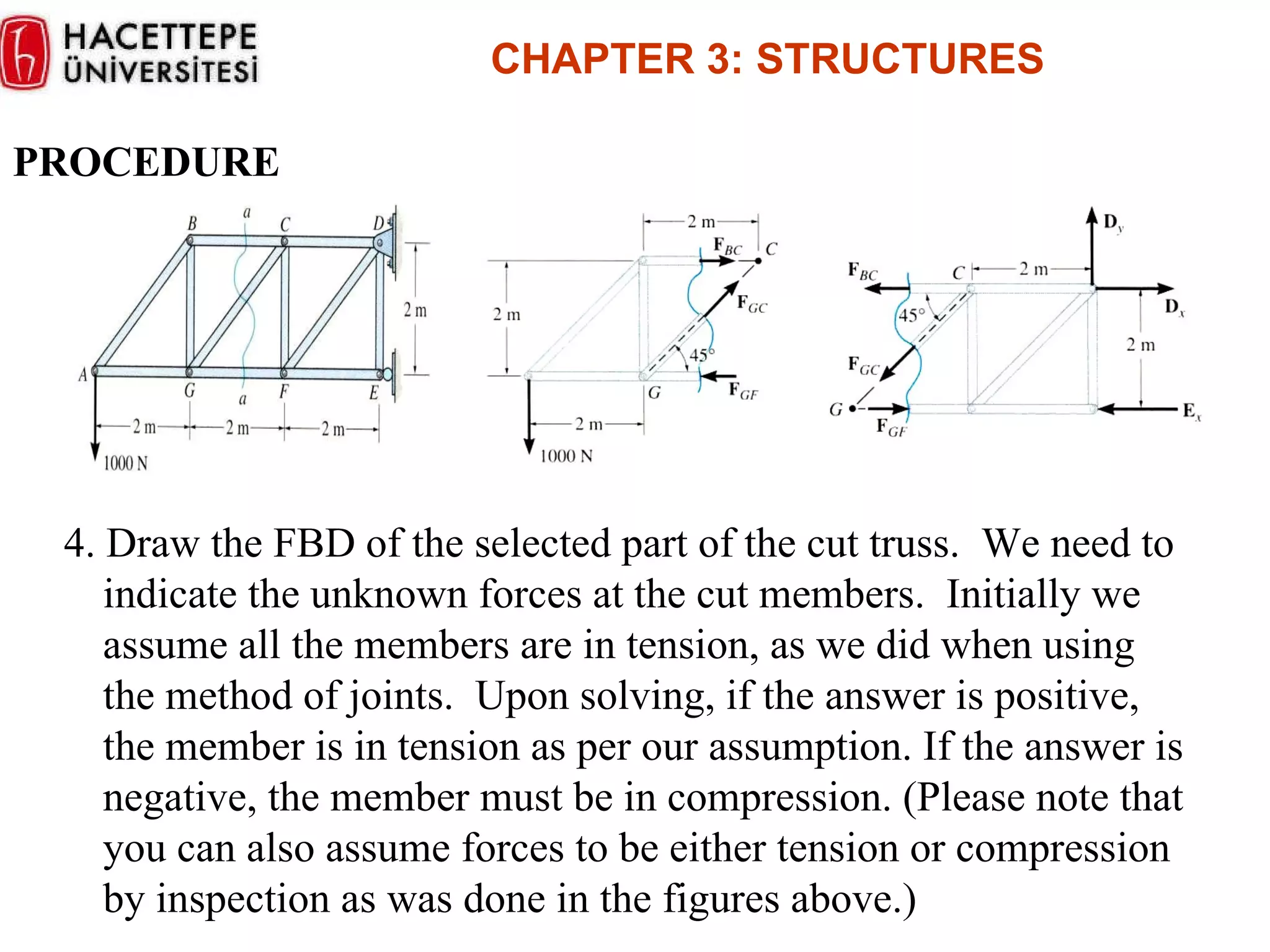
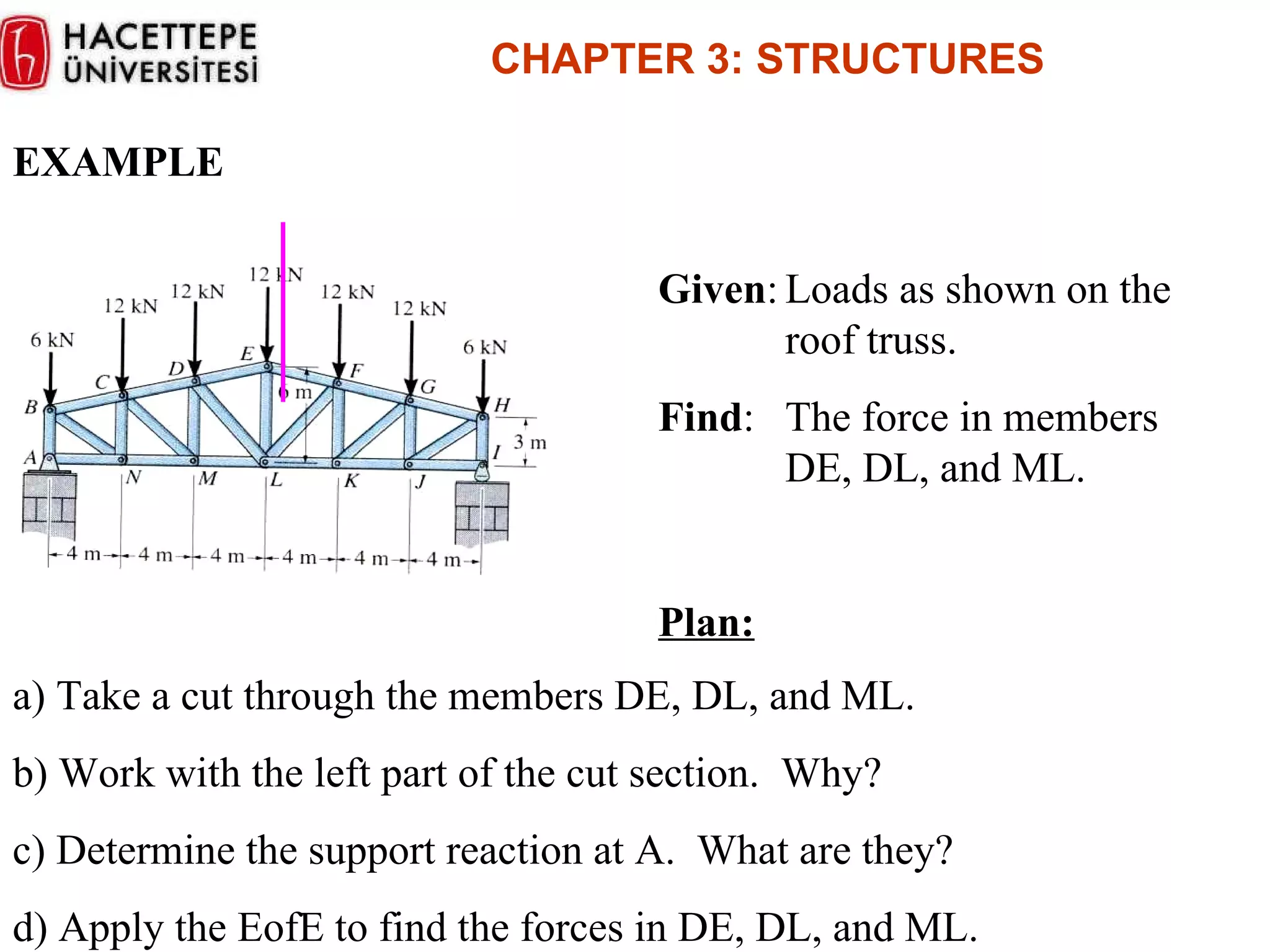
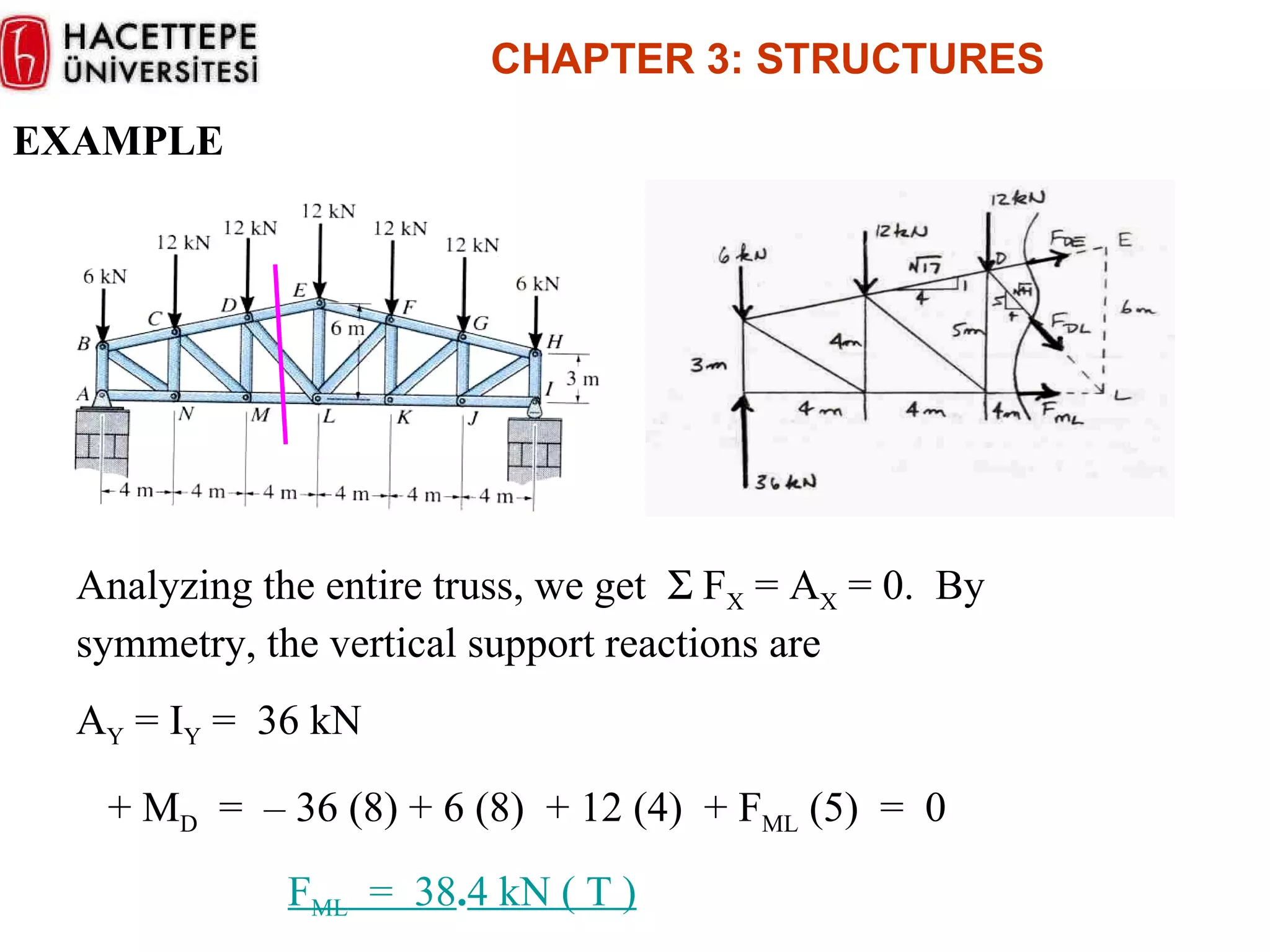
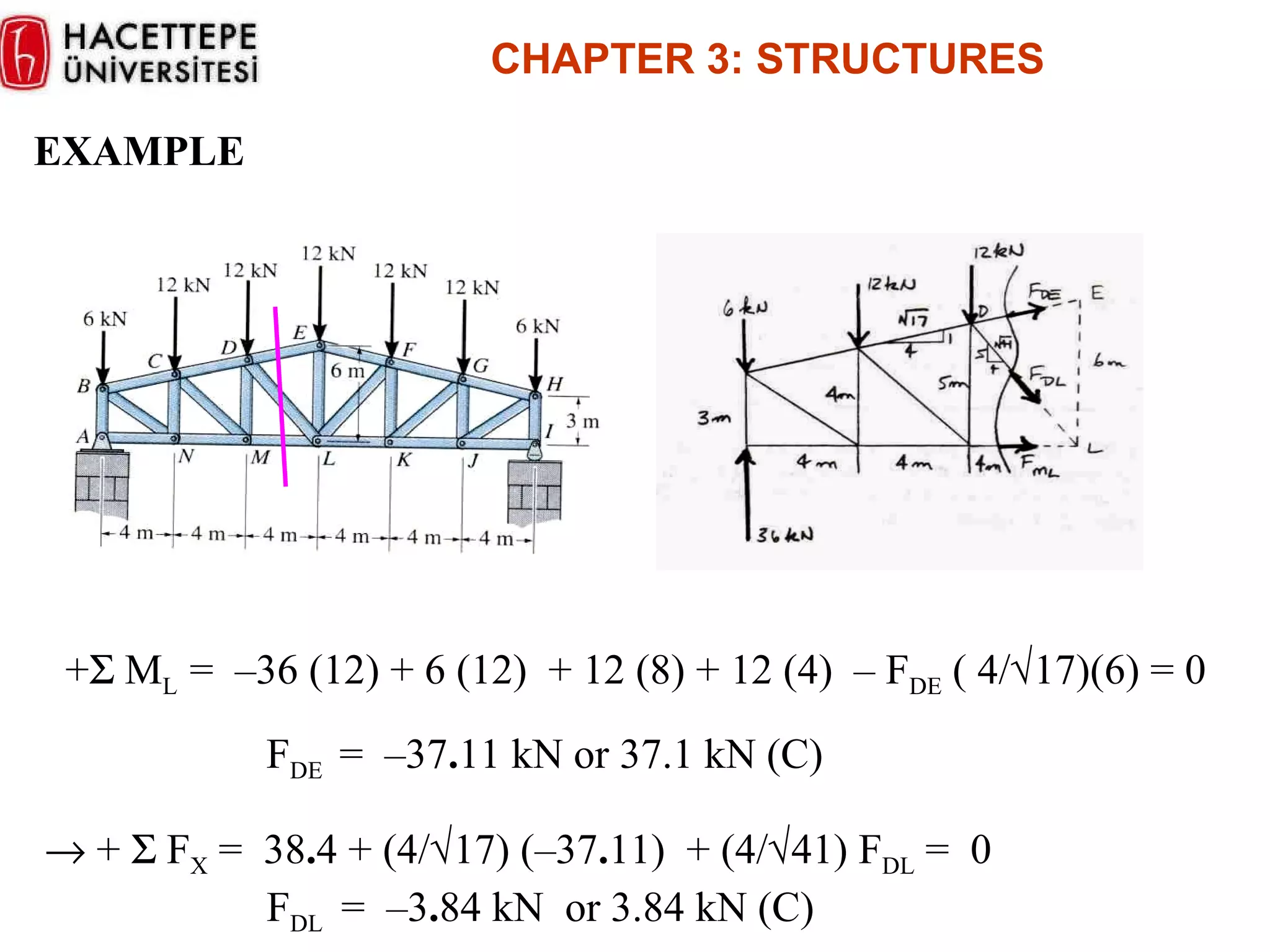
Method of sections for analyzing trusses, including cutting the truss and applying equilibrium equations.
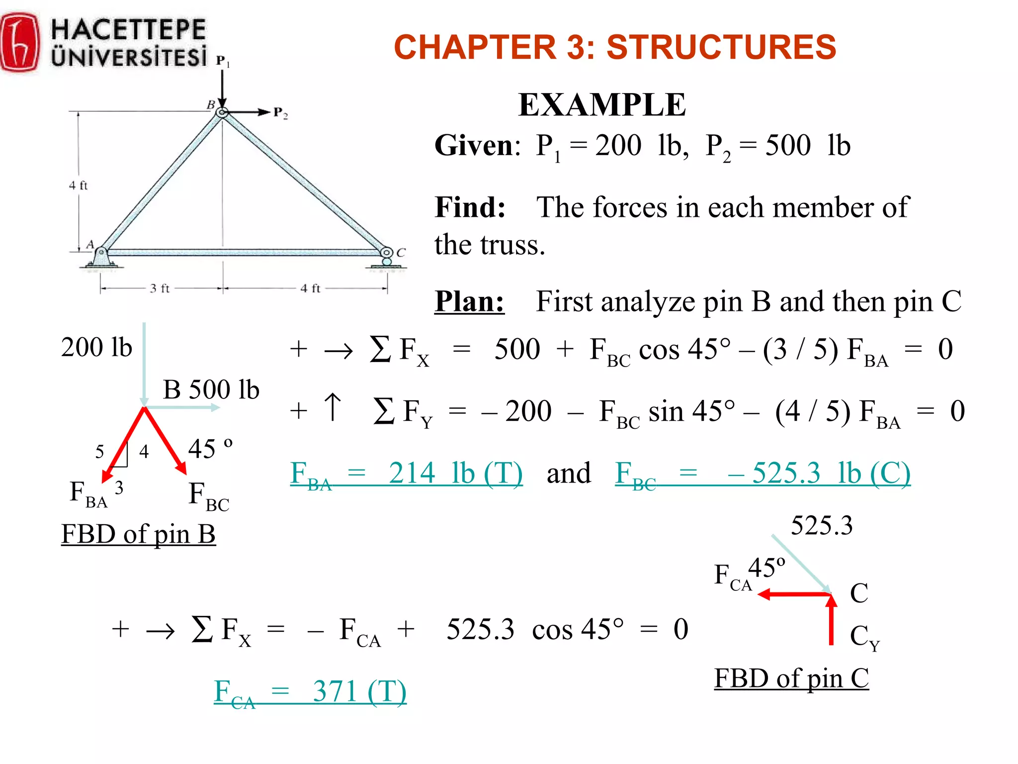
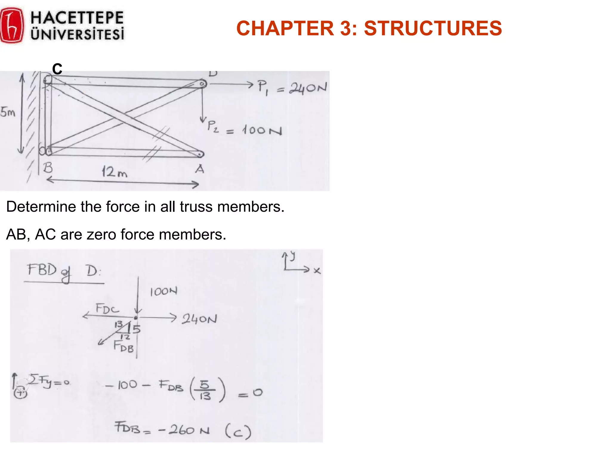
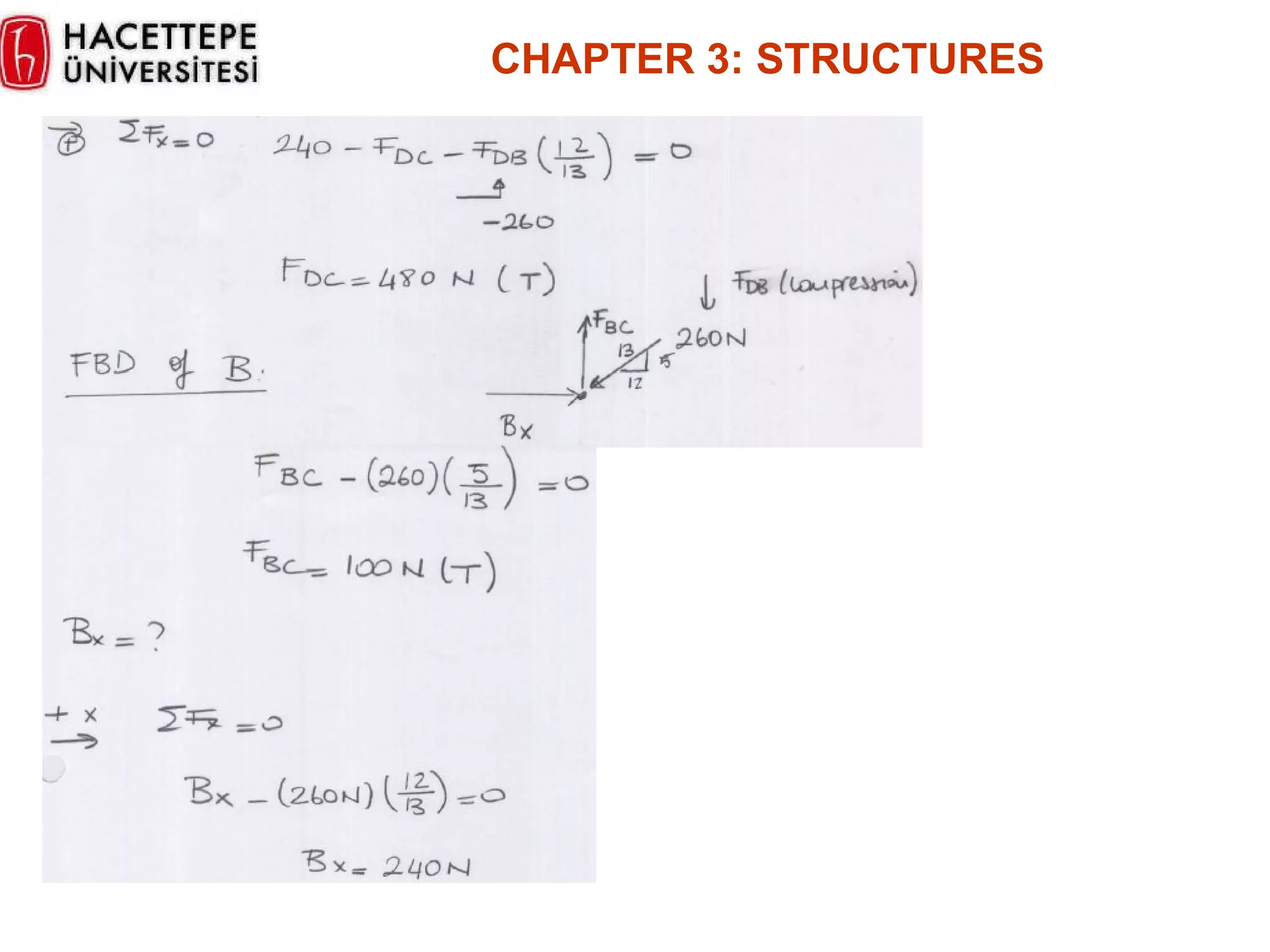
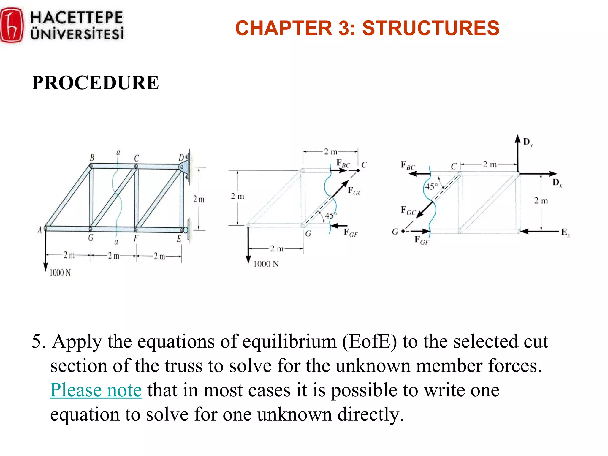
Worked examples of calculating forces in truss members using the method of sections and equilibrium.
CHAPTER 3: STRUCTURES Up to now, we worked with one single rigid body and external forces applied to it. We will deal with structures. STRUCTURE: A rigid made of several connected parts. Trusses: Designed to support loads made of straight two-force members. Frames: Designed to support loads containing at least one multiforce members. Machines: Designed to transmit and modify force. Contains at least one multiforce member. Trusses: One of the major types of engineering structures. Used in the design of bridges, buildings and roofs. Made of straight members connected at joints. Joints: bolt bolted, welded.
CHAPTER 3: STRUCTURES Analysis of Trusses: Assumptions: All loads are applied at joints. Weight of a truss is often neglected. W<<Applied Load If W is to be included, it is applied as W/2 at each end. The members are joined by smooth pins. Cannot support moment. This assumption is correct as long as the center lines of pinning members are concurrent.
4.
CHAPTER 3: STRUCTURES Consider the following trust:
CHAPTER 3: STRUCTURES Let’s dismember the truss and draw the FBD of each member. Pins should be in equilibrium. J points (pins)->2j equations (x, y) for 2 j unknowns. In this method of solving for the forces in truss members, the equilibrium of a joint (pin) is considered. All forces acting at the joint are shown in a FBD. This includes all external forces (including support reactions) as well as the forces acting in the members.
7.
STEPS FOR ANALYSIS1. If the support reactions are not given, draw a FBD of the entire truss and determine all the support reactions using the equations of equilibrium. 2. Draw the free-body diagram of a joint with one or two unknowns. Assume that all unknown member forces act in tension (pulling the pin) unless you can determine by inspection that the forces are compression loads. 3. Apply the scalar equations of equilibrium, F X = 0 and F Y = 0, to determine the unknown(s). If the answer is positive , then the assumed direction ( tension ) is correct, otherwise it is in the opposite direction (compression). 4. Repeat steps 2 and 3 at each joint in succession until all the required forces are determined. CHAPTER 3 : STRUCTURES
8.
EXAMPLE Given :P 1 = 200 lb, P 2 = 500 lb Find: The forces in each member of the truss. Plan: First analyze pin B and then pin C + F X = 500 + F BC cos 45 ° – (3 / 5) F BA = 0 + F Y = – 200 – F BC sin 45 ° – (4 / 5) F BA = 0 F BA = 214 lb (T) and F BC = – 525.3 lb (C) + F X = – F CA + 525.3 cos 45 ° = 0 F CA = 371 (T) CHAPTER 3 : STRUCTURES C C Y 525.3 F CA 45 º FBD of pin C 45 º F BC 200 lb B 500 lb F BA FBD of pin B 5 4 3
9.
ZERO-FORCE MEMBERS If a joint has only two non-colinear members and there is no external load or support reaction at that joint, then those two members are zero-force members. In this example members DE, CD, AF, and AB are zero force members. You can easily prove these results by applying the equations of equilibrium to joints D and A. Zero-force members can be removed (as shown in the figure) when analyzing the truss. CHAPTER 3 : STRUCTURES
10.
ZERO – FORCEMEMBERS If three members form a truss joint for which two of the members are collinear and there is no external load or reaction at that joint, then the third non-collinear member is a zero force member. Again, this can easily be proven. One can also remove the zero-force member, as shown, on the left, for analyzing the truss further. Please note that zero-force members are used to increase stability and rigidity of the truss, and to provide support for various different loading conditions. CHAPTER 3 : STRUCTURES
11.
CHAPTER 3: STRUCTURES Determine the force in all truss members. AB, AC are zero force members. C
In the methodof sections, a truss is divided into two parts by taking an imaginary “cut” (shown here as a-a) through the truss. Since truss members are subjected to only tensile or compressive forces along their length, the internal forces at the cut member will also be either tensile or compressive with the same magnitude. This result is based on the equilibrium principle and Newton’s third law . CHAPTER 3 : STRUCTURES THE METHOD OF SECTIONS
14.
STEPS FOR ANALYSIS1. Decide how you need to “cut” the truss. This is based on: a) where you need to determine forces, and, b) where the total number of unknowns does not exceed three (in general). 2. Decide which side of the cut truss will be easier to work with (minimize the number of reactions you have to find). 3. If required , determine the necessary support reactions by drawing the FBD of the entire truss and applying the EofE. CHAPTER 3 : STRUCTURES
15.
PROCEDURE 4. Drawthe FBD of the selected part of the cut truss. We need to indicate the unknown forces at the cut members. Initially we assume all the members are in tension, as we did when using the method of joints. Upon solving, if the answer is positive, the member is in tension as per our assumption. If the answer is negative, the member must be in compression. (Please note that you can also assume forces to be either tension or compression by inspection as was done in the figures above.) CHAPTER 3 : STRUCTURES
16.
PROCEDURE 5. Applythe equations of equilibrium (EofE) to the selected cut section of the truss to solve for the unknown member forces. Please note that in most cases it is possible to write one equation to solve for one unknown directly. CHAPTER 3 : STRUCTURES
17.
EXAMPLE Given :Loads as shown on the roof truss. Find : The force in members DE, DL, and ML. Plan: a) Take a cut through the members DE, DL, and ML. b) Work with the left part of the cut section. Why? c) Determine the support reaction at A. What are they? d) Apply the EofE to find the forces in DE, DL, and ML. CHAPTER 3 : STRUCTURES
18.
EXAMPLE Analyzing theentire truss, we get F X = A X = 0. By symmetry, the vertical support reactions are A Y = I Y = 36 kN CHAPTER 3 : STRUCTURES + M D = – 36 (8) + 6 (8) + 12 (4) + F ML (5) = 0 F ML = 38 . 4 kN ( T )
19.
EXAMPLE + F X = 38 . 4 + (4/ 17) ( – 37 . 11) + (4/ 41) F DL = 0 F DL = – 3 . 84 kN or 3.84 kN (C) CHAPTER 3 : STRUCTURES + M L = – 36 (12) + 6 (12) + 12 (8) + 12 (4) – F DE ( 4/ 17)(6) = 0 F DE = – 37 . 11 kN or 37.1 kN (C)