Downloaded 503 times
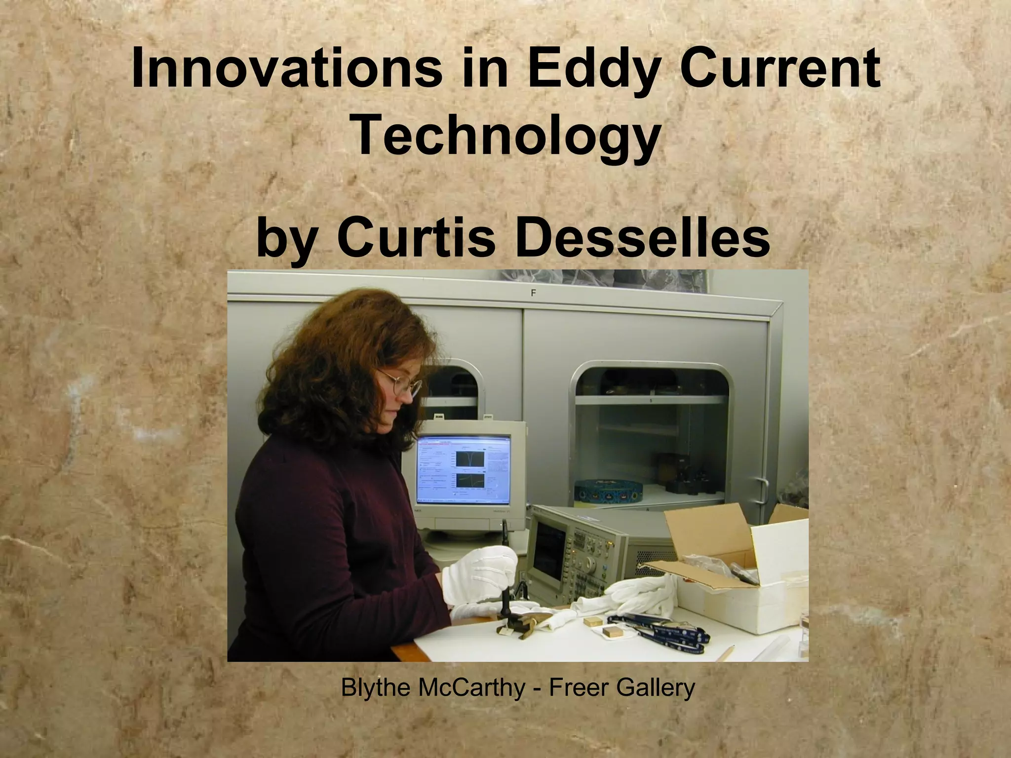
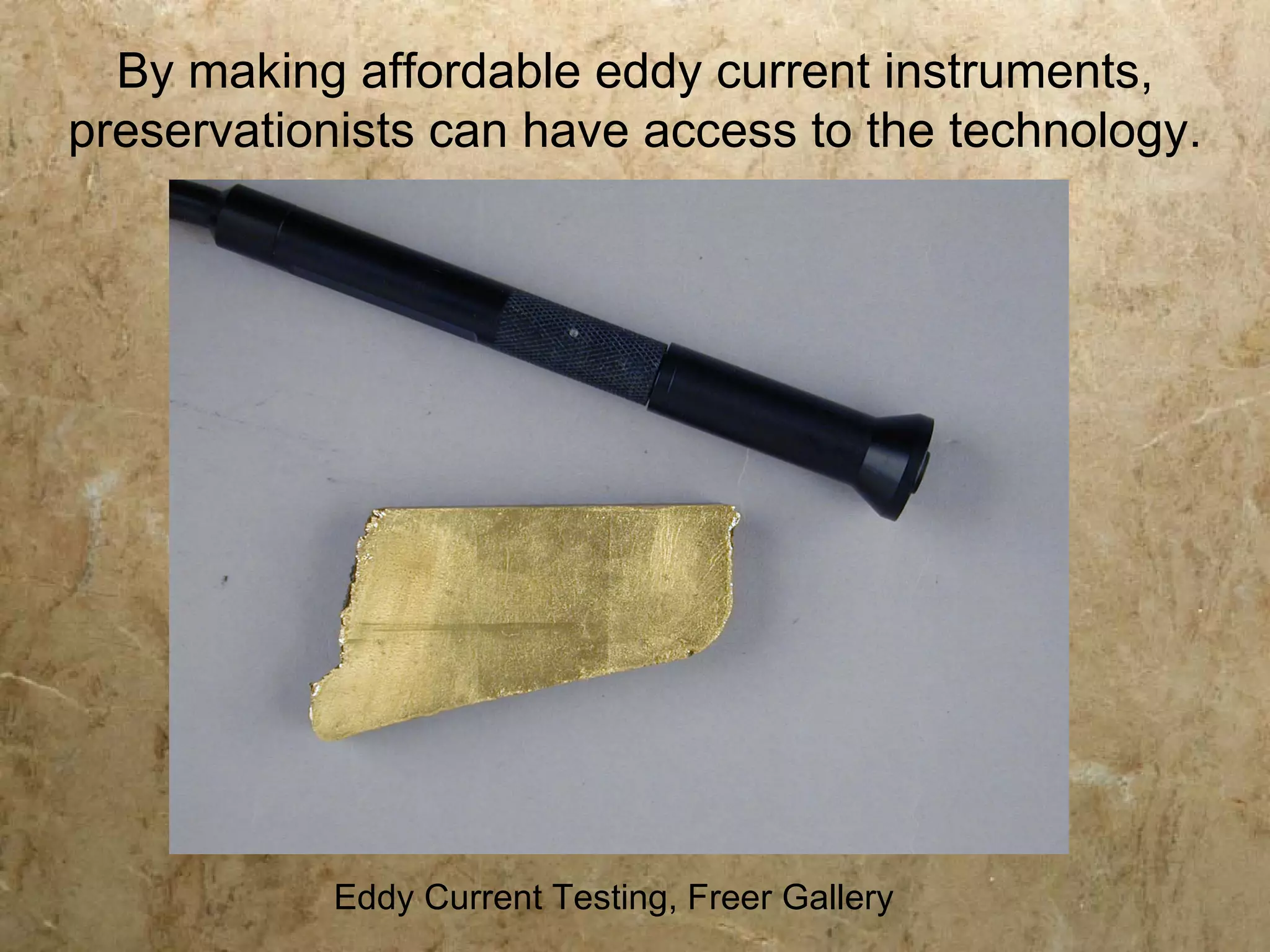
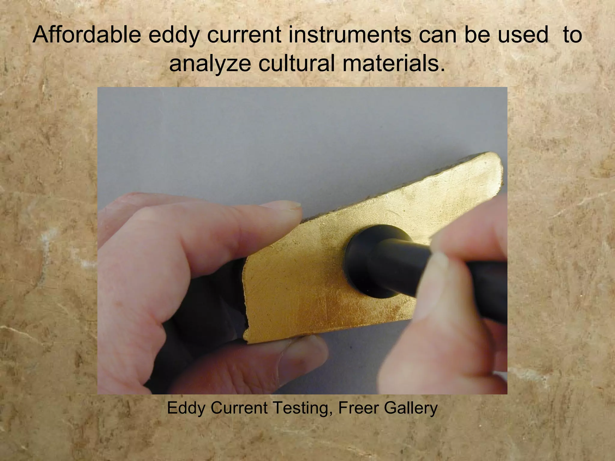
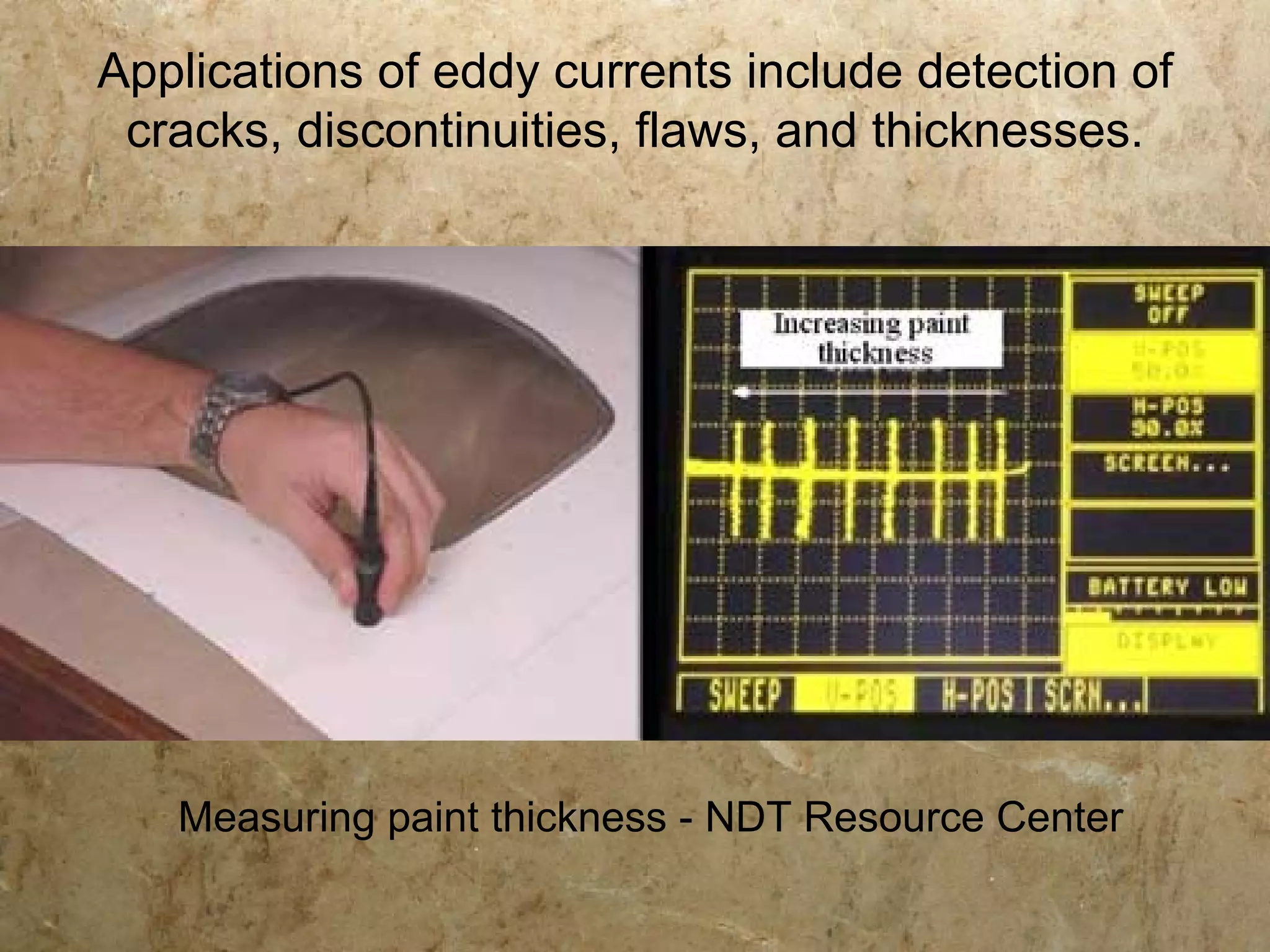
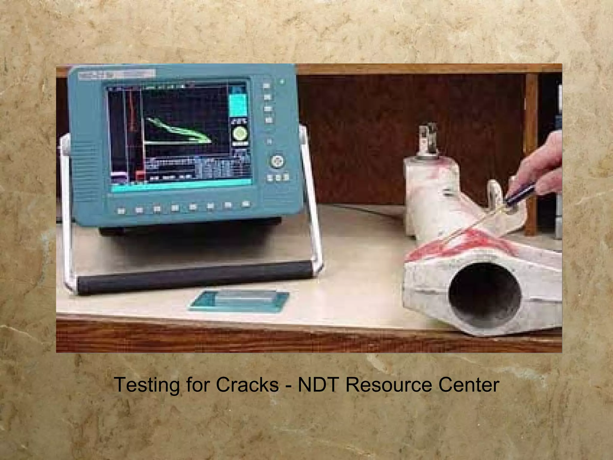


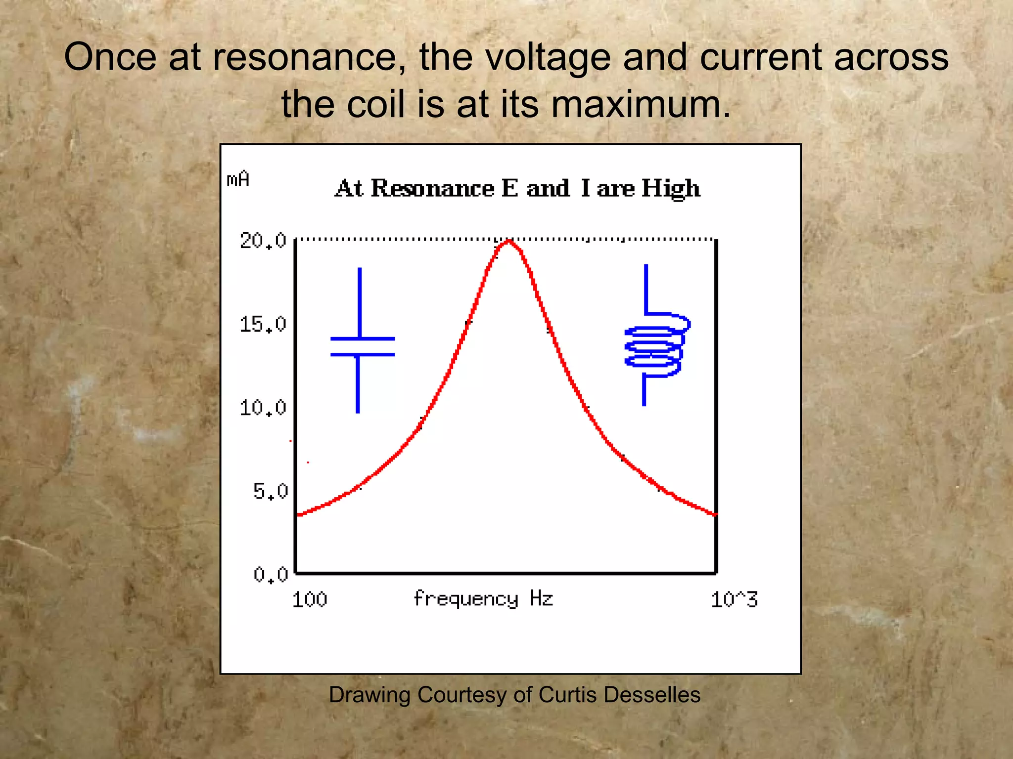
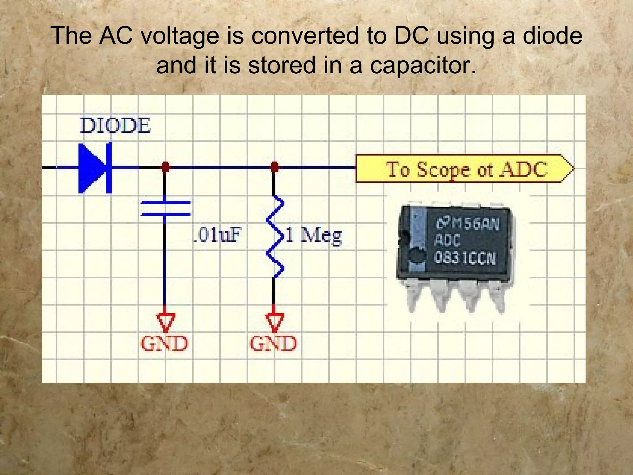
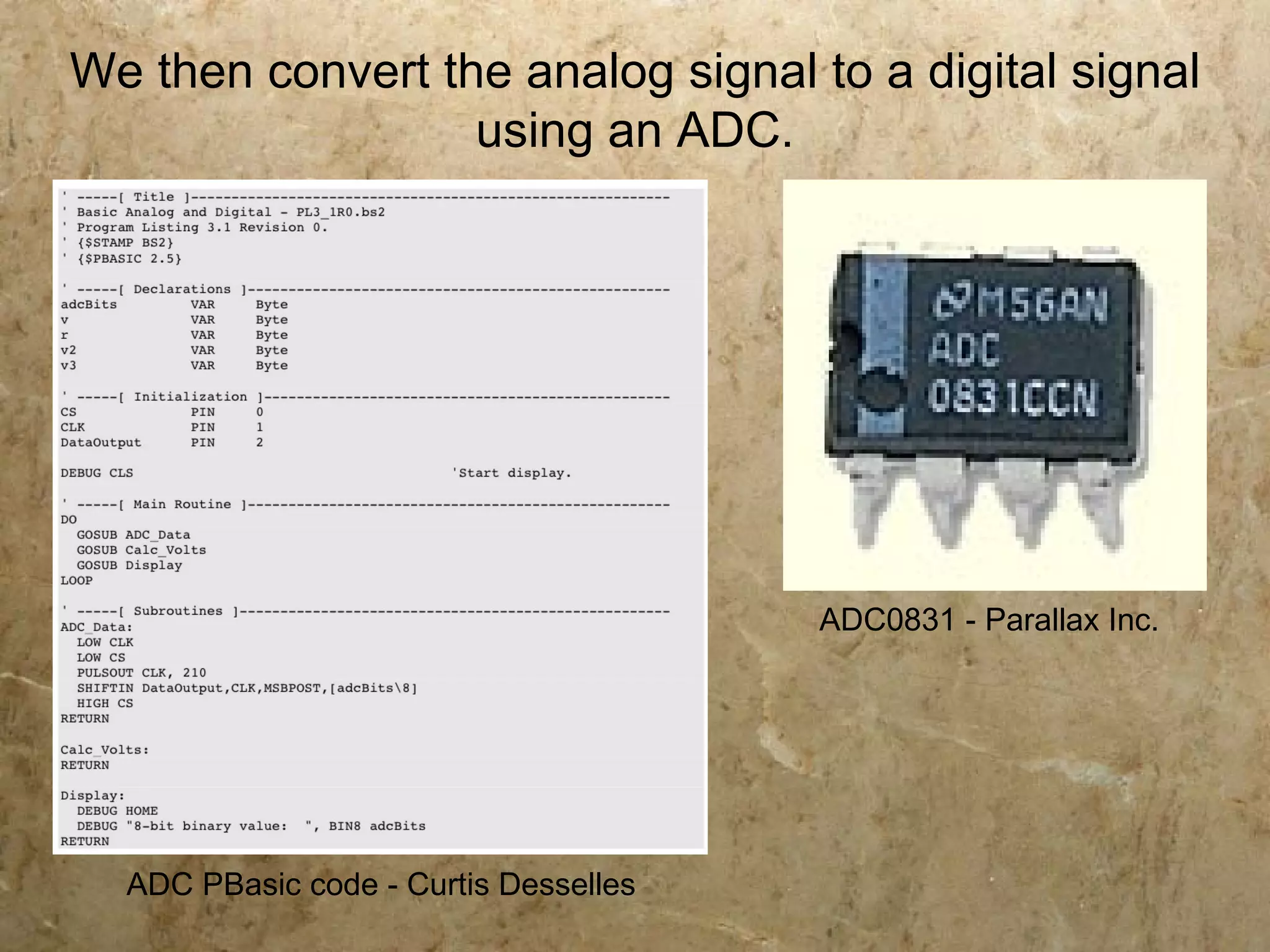
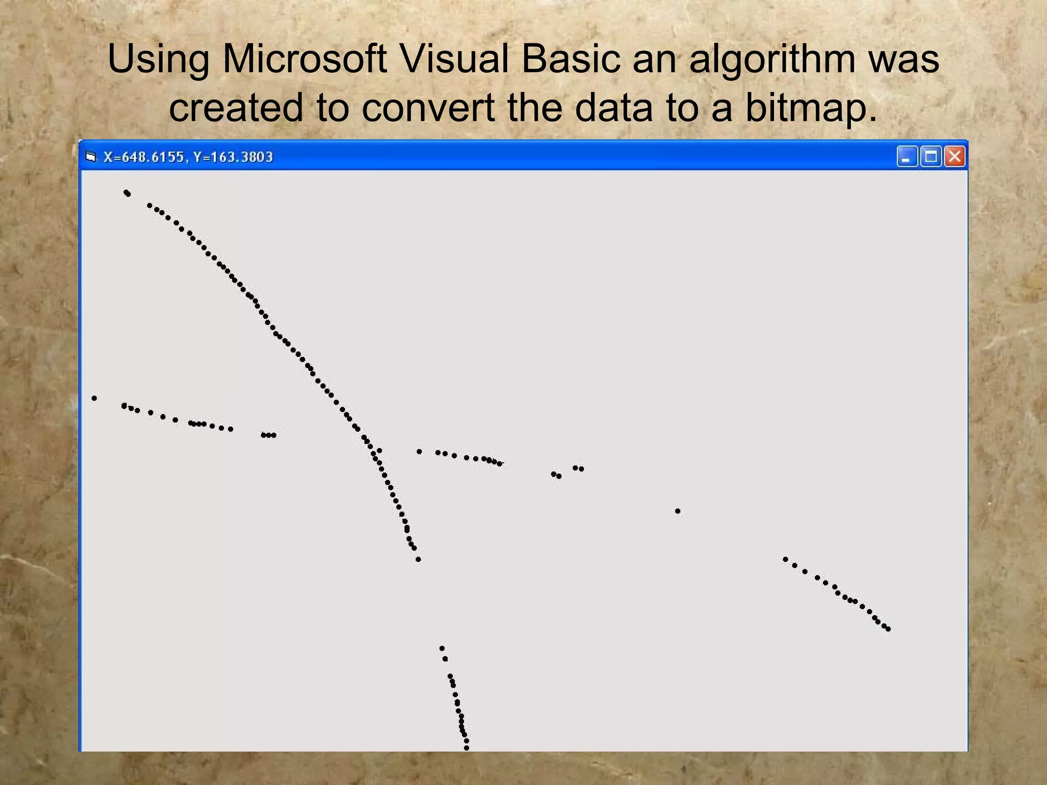
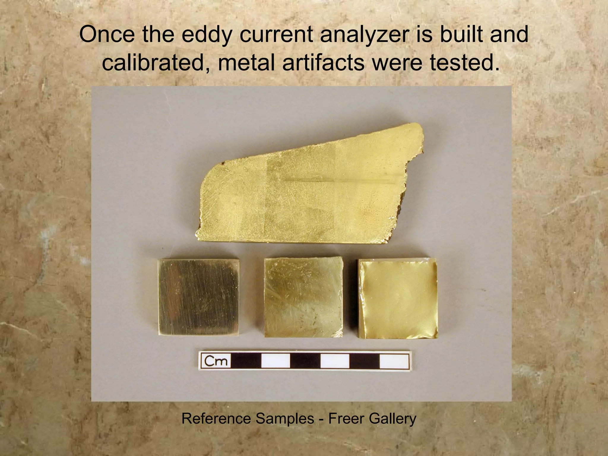
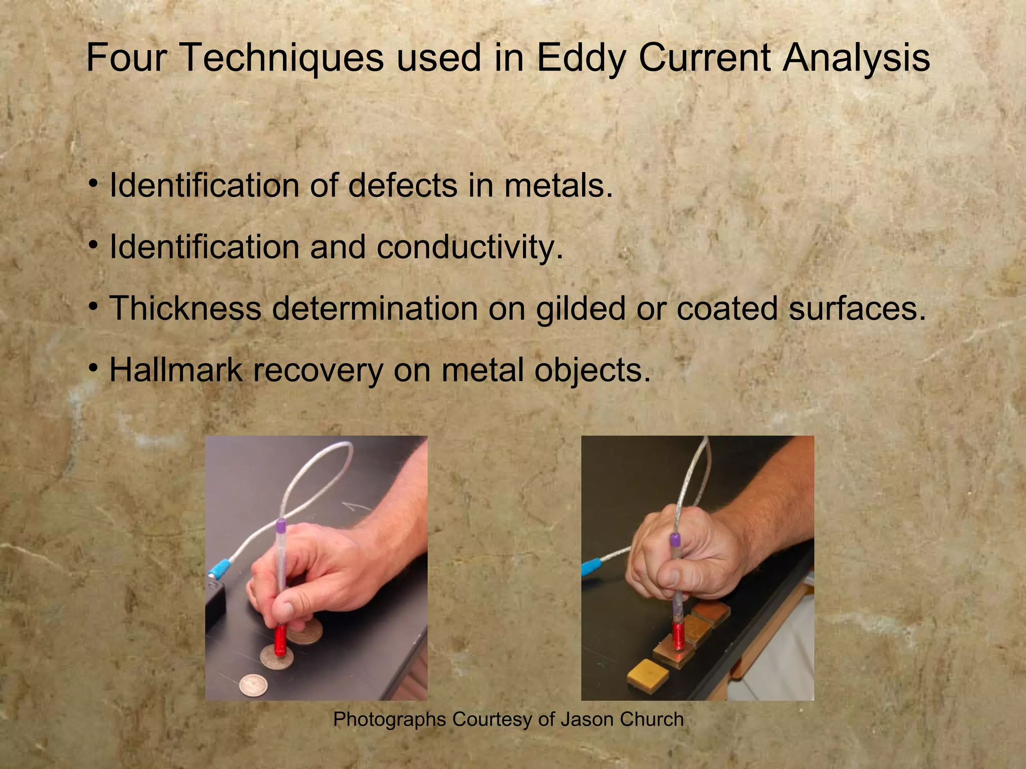
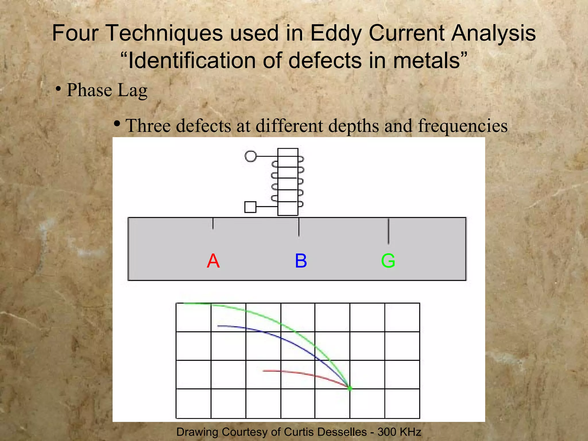
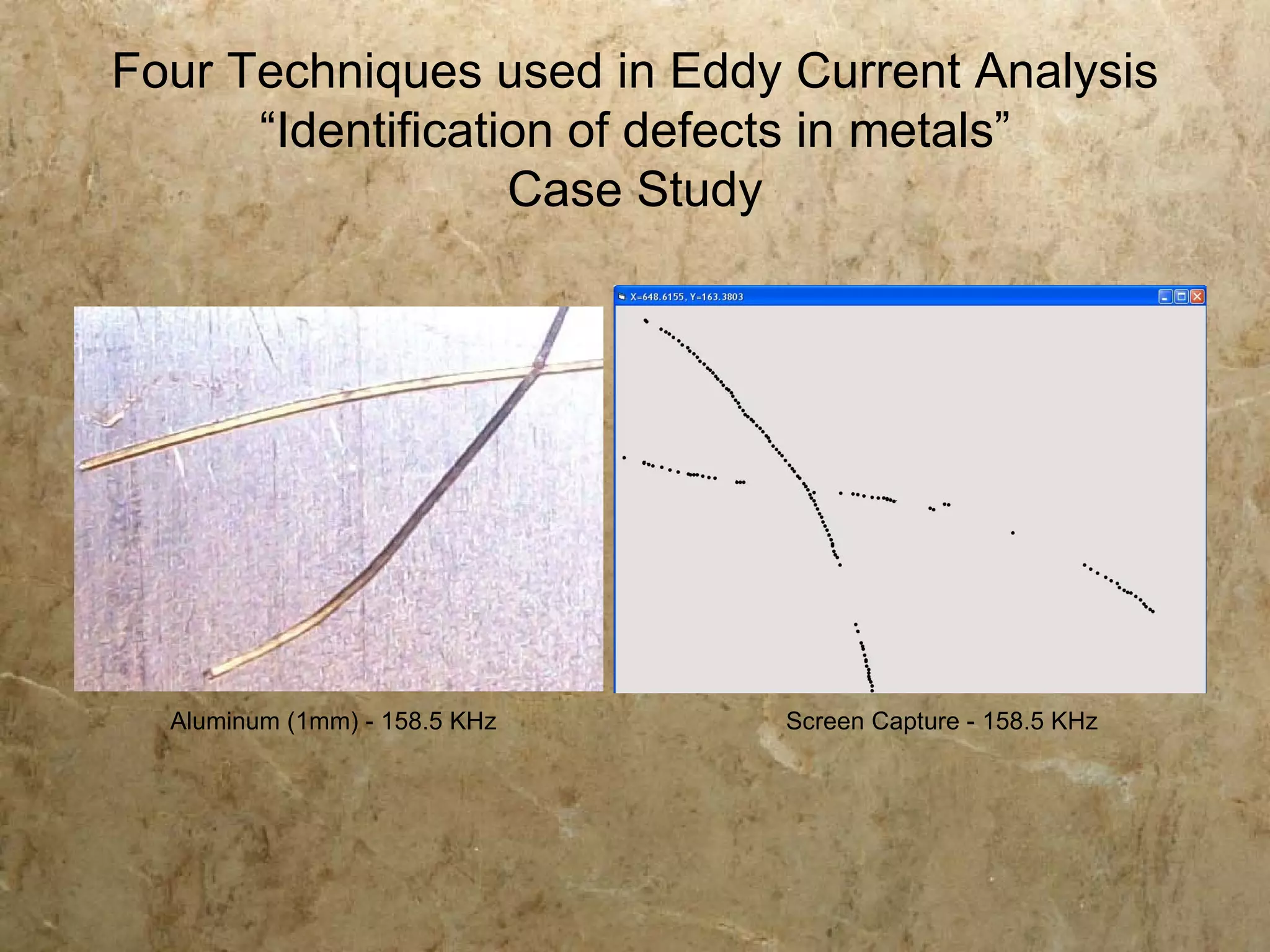
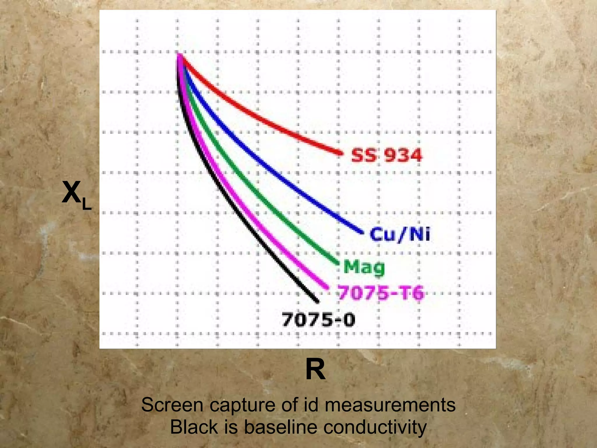
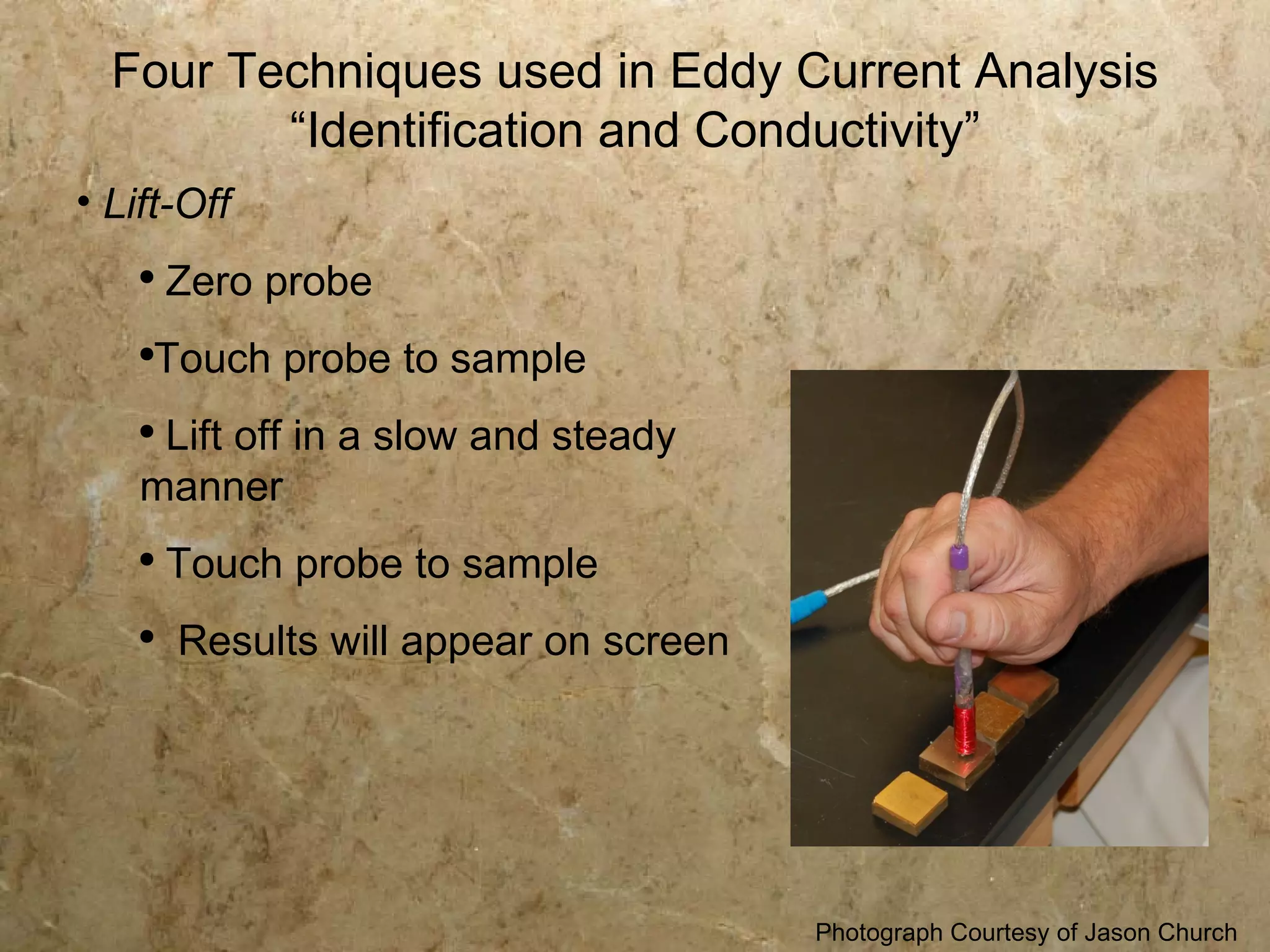
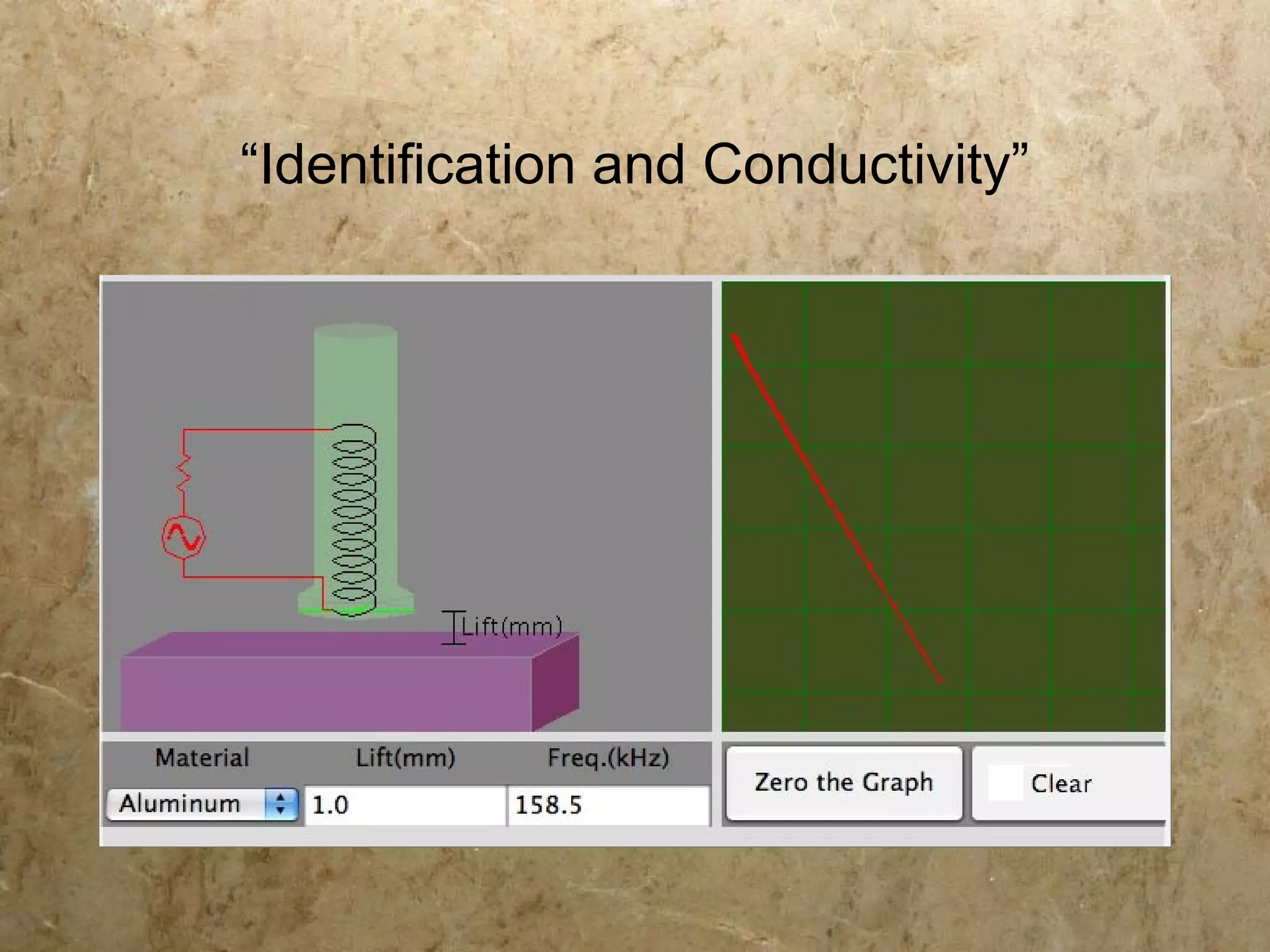
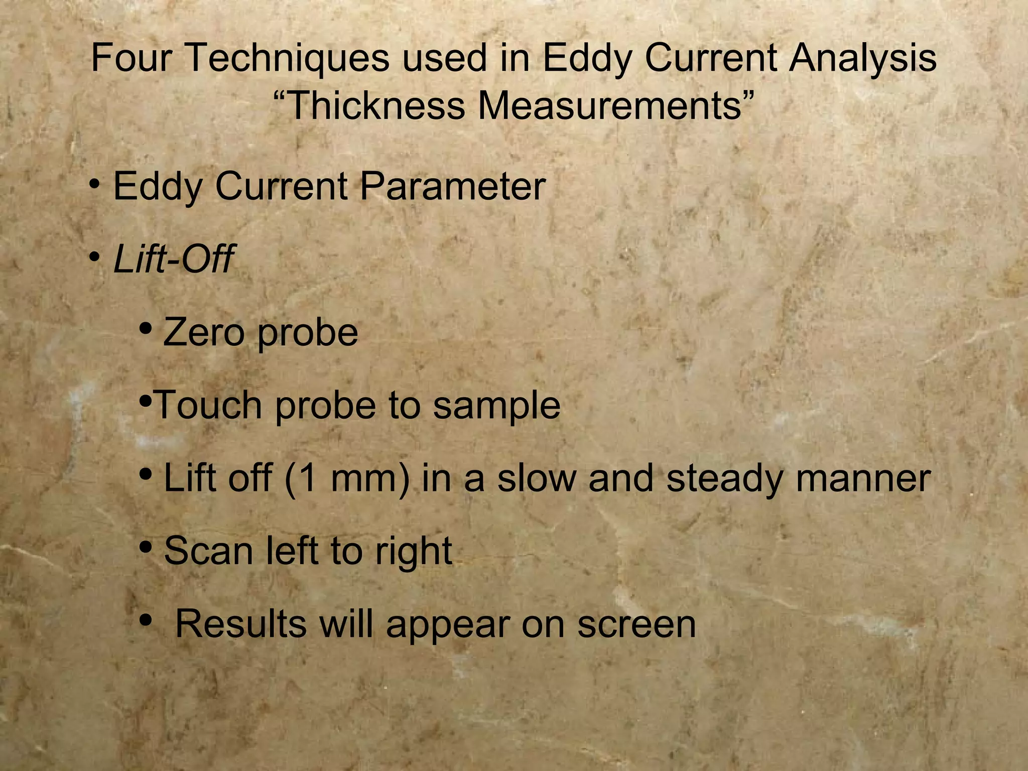
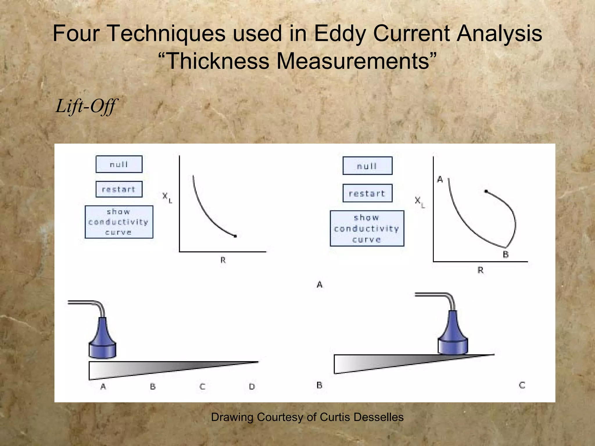
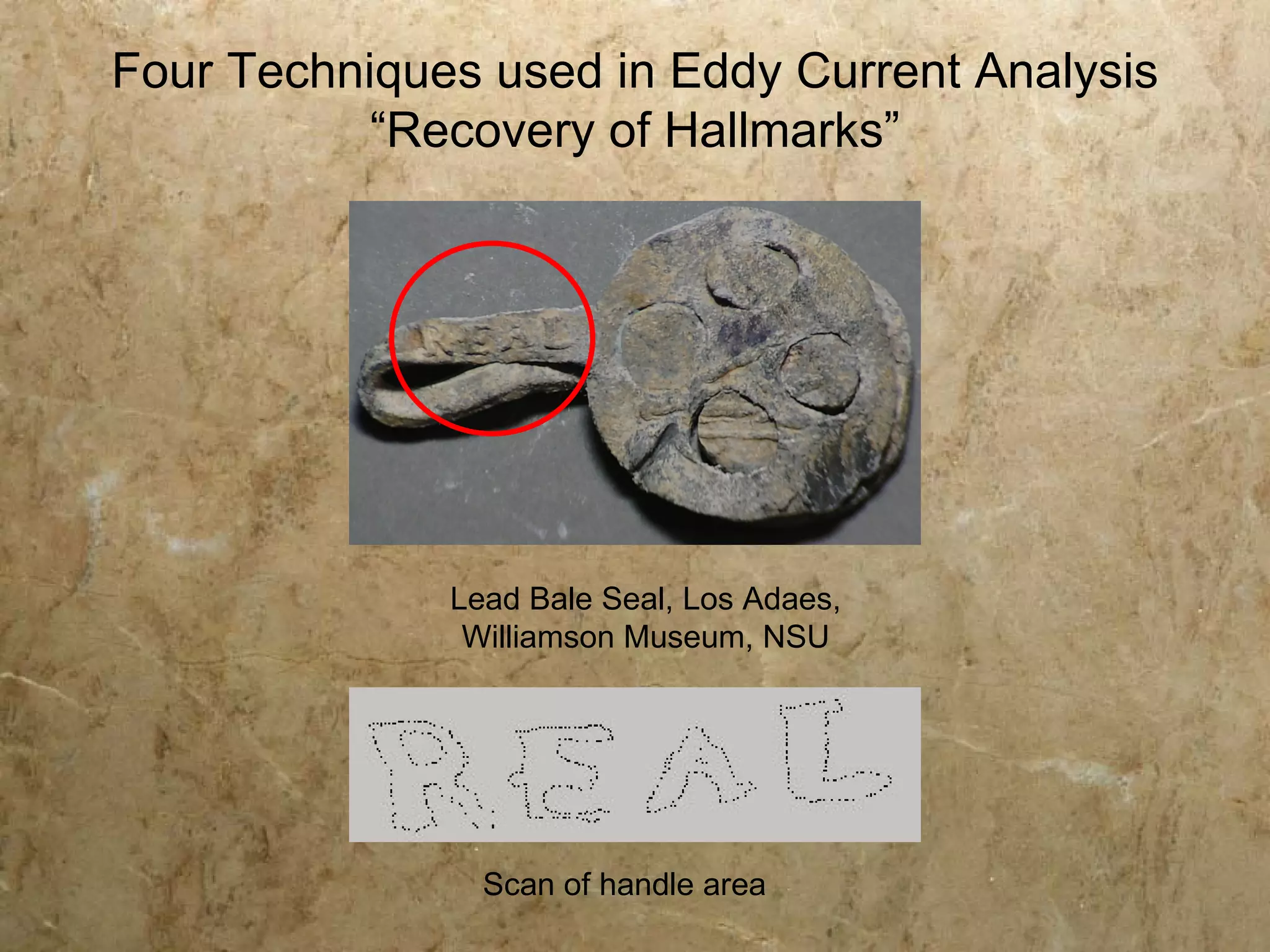
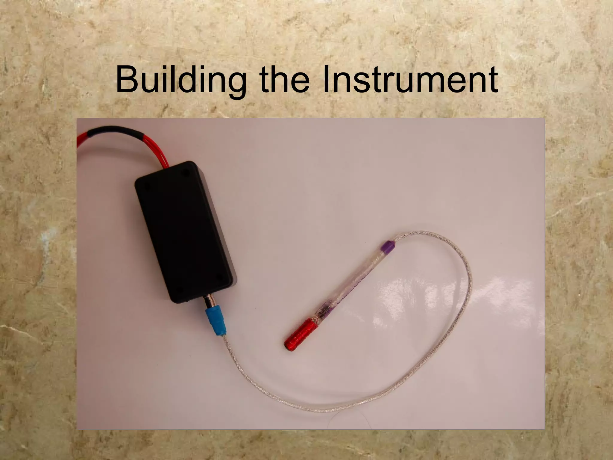
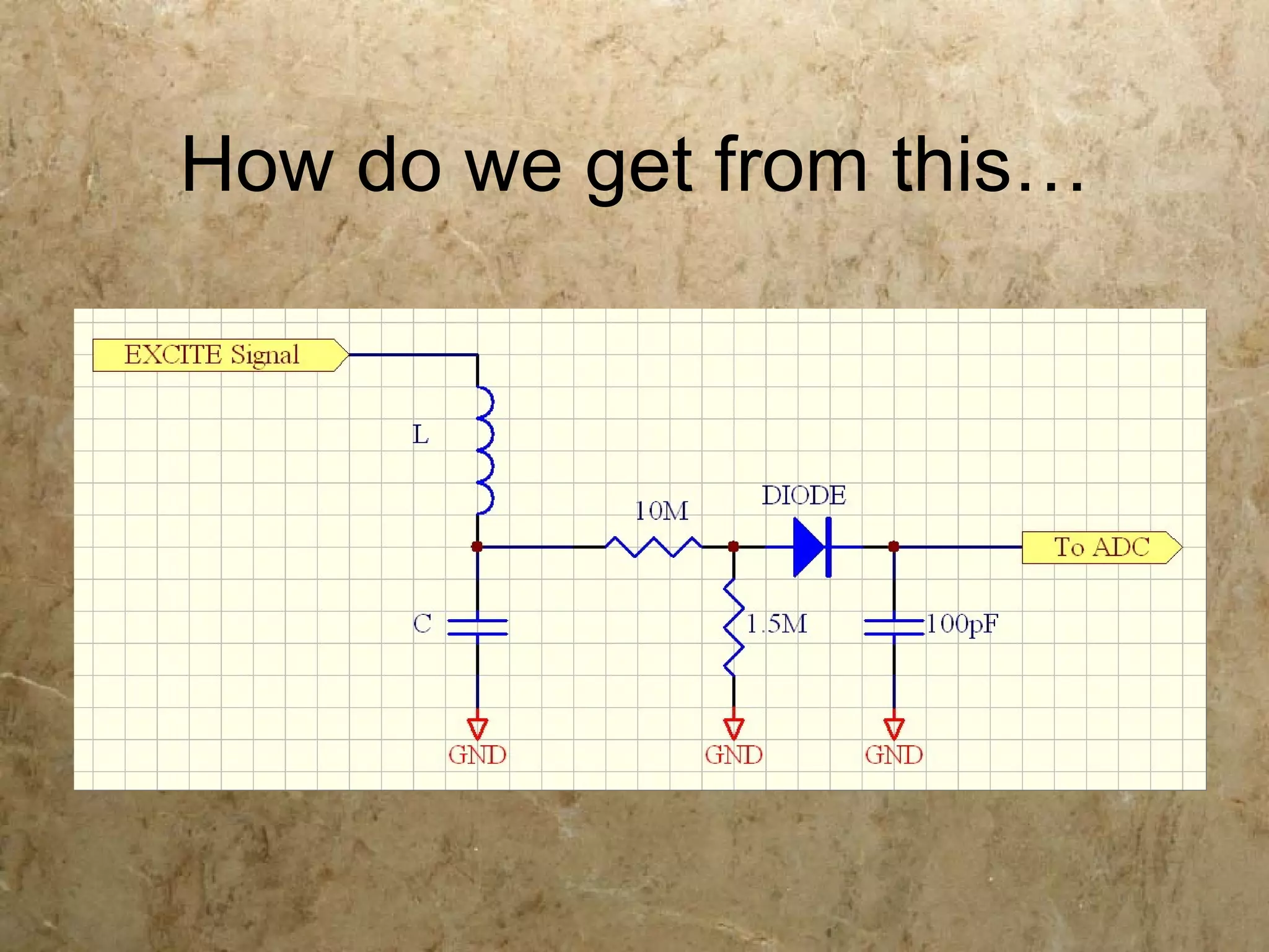
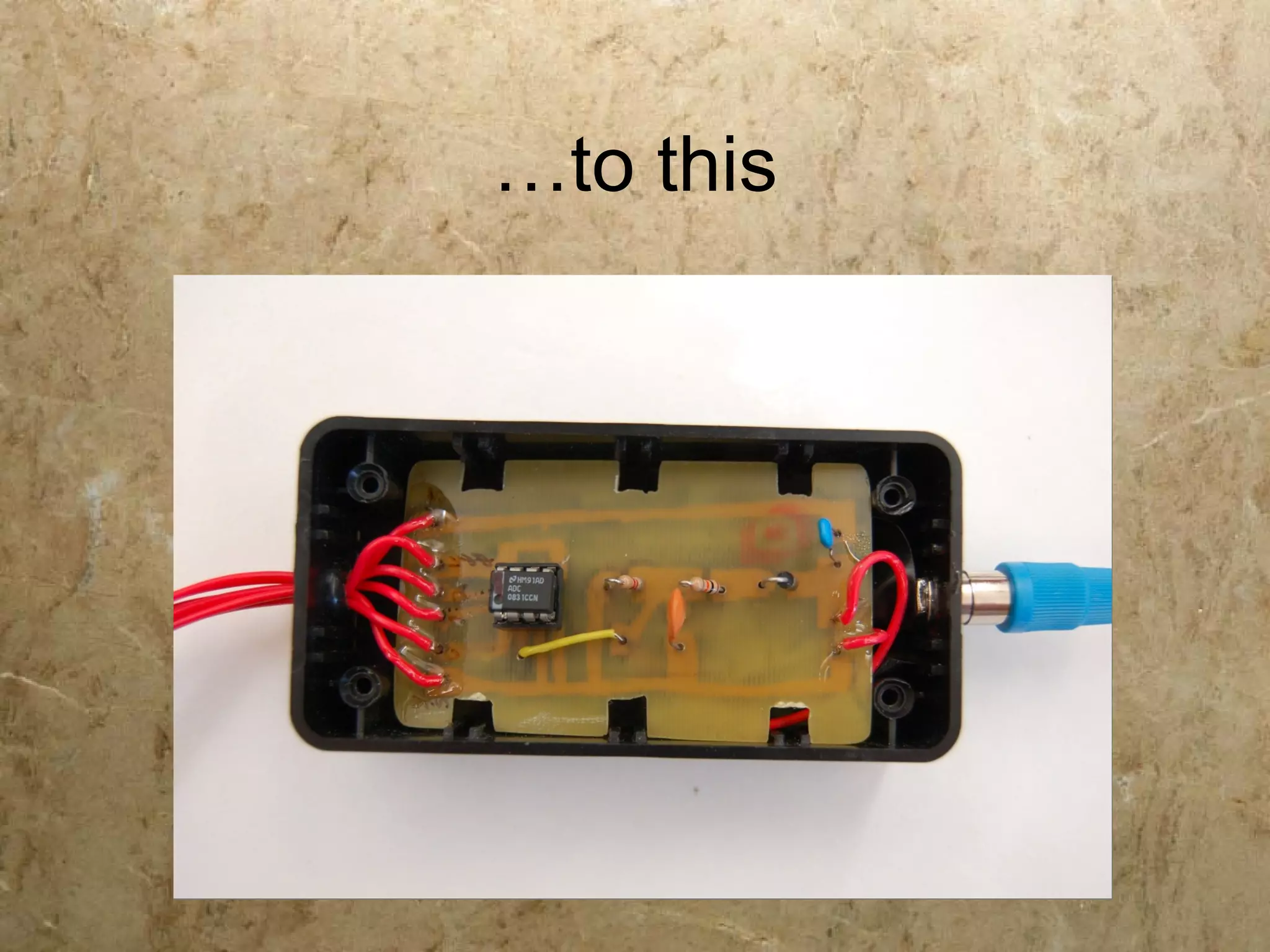
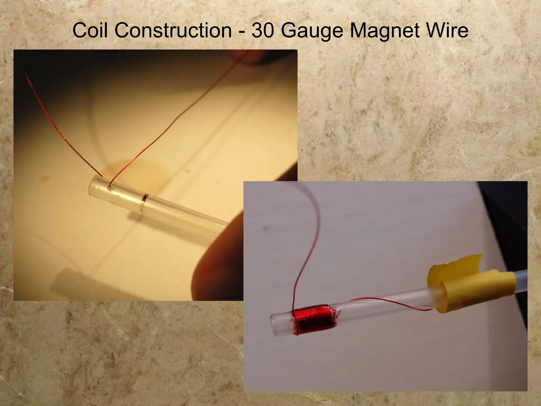
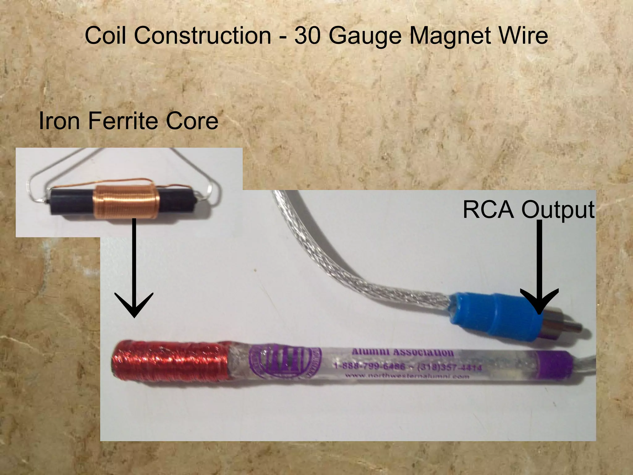
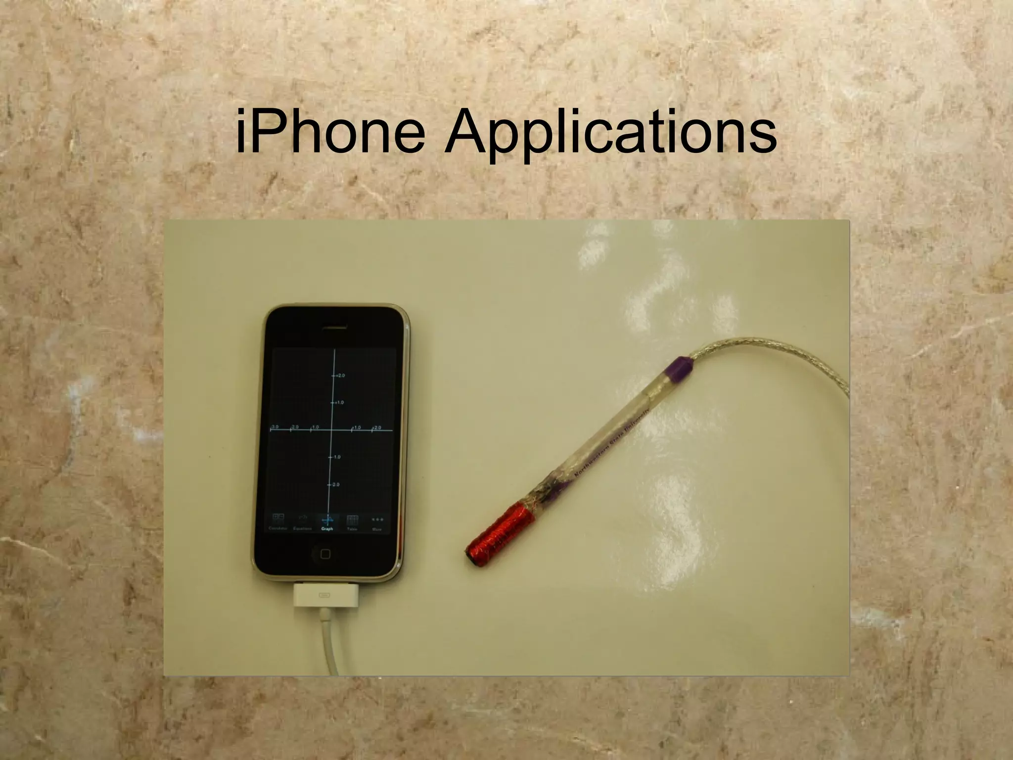
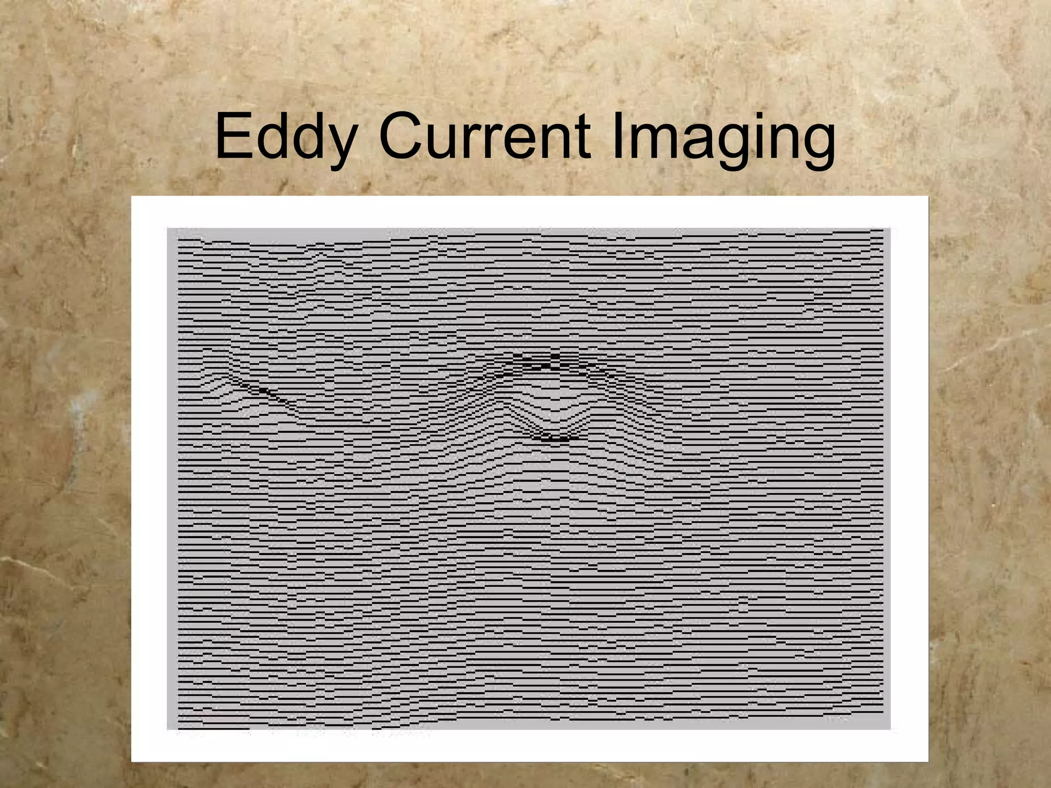
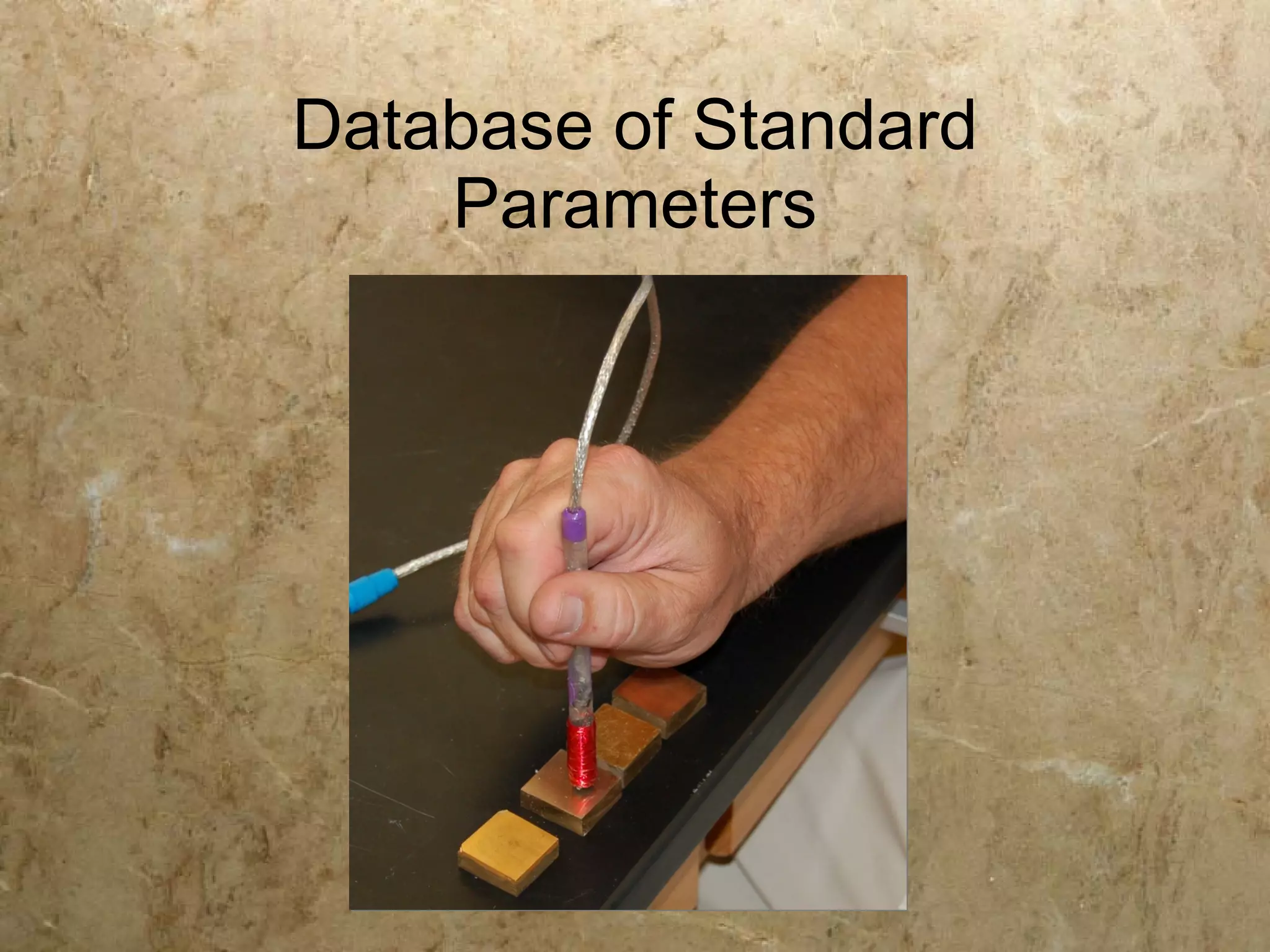
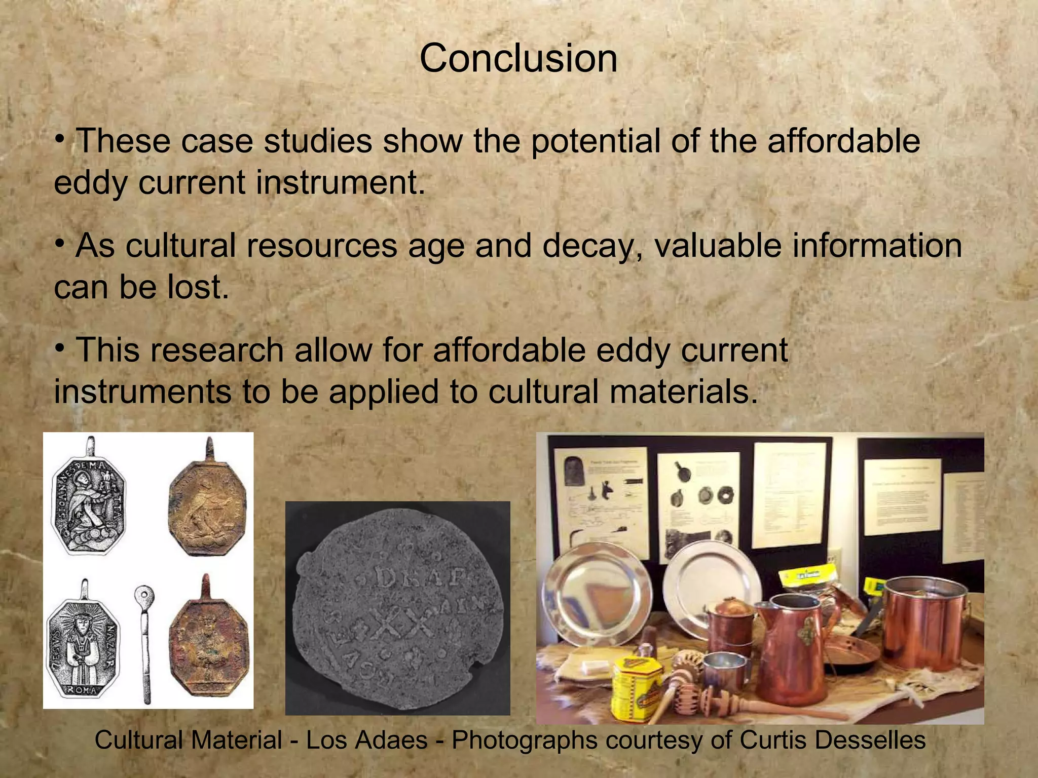

The document discusses advancements in eddy current technology for non-destructive testing of cultural heritage materials. It highlights how affordable eddy current instruments can aid preservationists in detecting flaws, measuring thickness, and recovering hallmarks in artifacts. The research contributes to the development of simple, effective tools for analyzing cultural materials that are at risk of degradation.


![Underwater welding 1[1]](https://cdn.slidesharecdn.com/ss_thumbnails/underwaterwelding11-180325142223-thumbnail.jpg?width=640&height=640&fit=bounds)


