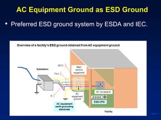
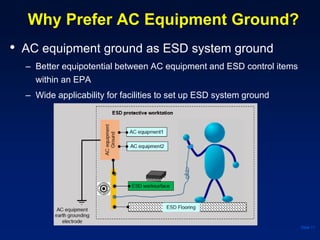
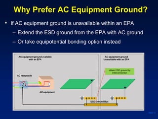
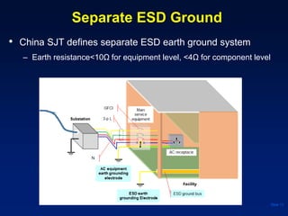
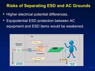
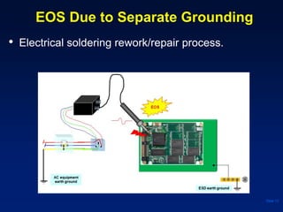
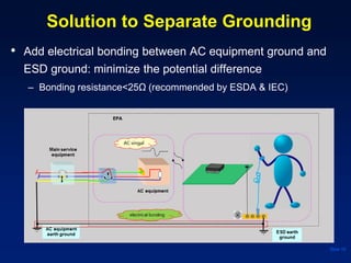
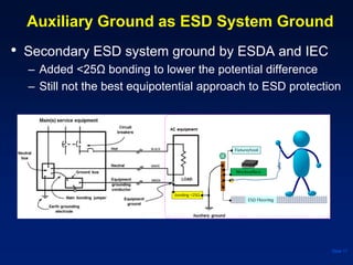
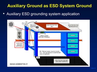
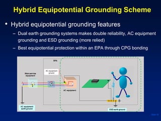
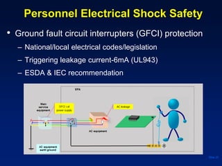
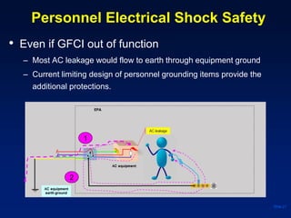
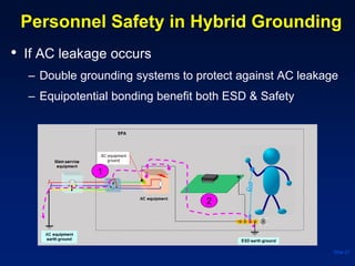
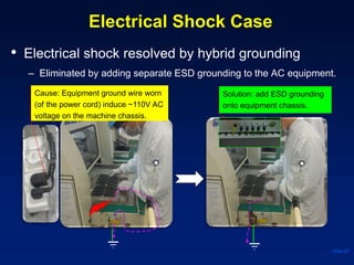
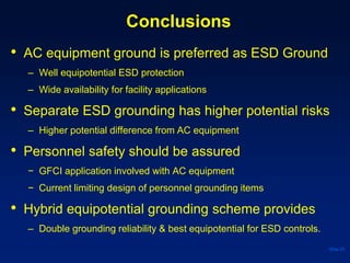
2016 EOS/ESD Manufacturing Symposium
China
Factory ESD Grounding System
Design Application
Copper Hou
Objectives
● This paper would discuss the followings:
– To demonstrate how grounding protect objects
from being damaged by ESD
– To analyze the effectiveness of different ESD
grounding schemes
– To propose a reliable ESD grounding approach to
achieve both personnel safety and ESD
protections to sensitive items.
Slide 2
Background
• 3 types ESD ground systems are often discussed
– AC equipment ground based
– Separated from AC equipment ground
– Auxiliary ground
Slide 3
Safety Concern of AC Leakage from AC Equipment
(problem with AC equipment based grounding)
• Grounding risks related with AC equipment
– Electrical shock hazard against ground with AC leakage
Slide 4
How Grounding Avoids ESD Happening?
● Grounding Principle
– Potential differences is the cause to make charge transferring.
– Grounding equals all the objects (conductive, dissipative) at the same
potential with the earth (virtually zero) by the electrical connection.
– There would be no charge transferring between grounded objects
(conductive, dissipative), therefore no ESD events could occur.
Slide 5
● Note: grounding is ineffective to insulators.
Typical ESD Grounding Application
Slide 6
● All conductive and dissipative items in an EPA are grounded.
How Grounding Protect ESD?
● Equipotential bonding Principle
– Bonding equals the objects at the same potential, usually not near the
earth potential.
– No potential differences, no charge transferring (no ESD).
Slide 7
● No potential difference, makes No ESD occurrence!
Equal potential maintained between V1 and V2.
Typical Equipotential Bonding ESD
Protection in Field Service Application
Slide 8
IEC 61340-5-1
● Personnel and worksurface are bonded to the equipment.
Ref. industrial grounding standards
• ESDA ANSI/ESD S20.20
– ANSI/ESD S6.1, NFPA 70 (Article 250 part Ⅲ, grounding
electrode system)
• IEC 61340-5-1
– IEC 61340-5-1, Country/region National Electrical Codes
• China, SJT: separate ESD earth ground
– SJ/T 10533 for equipment level
– SJ/T 10630 for component level
Slide 9
AC Equipment Ground as ESD Ground
• Preferred ESD ground system by ESDA and IEC.
Slide 10
Why Prefer AC Equipment Ground?
• AC equipment ground as ESD system ground
– Better equipotential between AC equipment and ESD control items
within an EPA
– Wide applicability for facilities to set up ESD system ground
Slide 11
Why Prefer AC Equipment Ground?
• If AC equipment ground is unavailable within an EPA
– Extend the ESD ground from the EPA with AC ground
– Or take equipotential bonding option instead
Slide 12
Separate ESD Ground
• China SJT defines separate ESD earth ground system
– Earth resistance<10Ω for equipment level, <4Ω for component level
Slide 13
Risks of Separating ESD and AC Grounds
• Higher electrical potential differences.
• Equipotential ESD protection between AC
equipment and ESD items would be weakened.
Slide 14
EOS Due to Separate Grounding
• Electrical soldering rework/repair process.
Slide 15
Solution to Separate Grounding
• Add electrical bonding between AC equipment ground and
ESD ground: minimize the potential difference
– Bonding resistance<25Ω (recommended by ESDA & IEC)
Slide 16
Auxiliary Ground as ESD System Ground
• Secondary ESD system ground by ESDA and IEC
– Added <25Ω bonding to lower the potential difference
– Still not the best equipotential approach to ESD protection
Slide 17
Auxiliary Ground as ESD System Ground
• Auxiliary ESD grounding system application
Slide 18
NASA-HDBK8739.21
Hybrid Equipotential Grounding Scheme
• Hybrid equipotential grounding features
– Dual earth grounding systems makes double reliability, AC equipment
grounding and ESD grounding (more relied)
– Best equipotential protection within an EPA through CPG bonding
Slide 19
Personnel Electrical Shock Safety
• Ground fault circuit interrupters (GFCI) protection
– National/local electrical codes/legislation
– Triggering leakage current-6mA (UL943)
– ESDA & IEC recommendation
Slide 20
Personnel Electrical Shock Safety
• Even if GFCI out of function
– Most AC leakage would flow to earth through equipment ground
– Current limiting design of personnel grounding items provide the
additional protections.
Slide 21
1
2
Personnel Electrical Shock Safety
• Personnel electrical safety concern in ESD controls
– Current limiting shall be considered in exposure of
hazardous AC electrical sources
– 0.7 mA peak current limit defined by UL 1950.
Slide 22
Current limiting shall be considered
Personnel Safety in Hybrid Grounding
• If AC leakage occurs
– Double grounding systems to protect against AC leakage
– Equipotential bonding benefit both ESD & Safety
Slide 23
1
2
Electrical Shock Case
• Electrical shock resolved by hybrid grounding
– Eliminated by adding separate ESD grounding to the AC equipment.
Slide 24
Cause: Equipment ground wire worn
(of the power cord) induce ~110V AC
voltage on the machine chassis.
Solution: add ESD grounding
onto equipment chassis.
Conclusions
• AC equipment ground is preferred as ESD Ground
– Well equipotential ESD protection
– Wide availability for facility applications
• Separate ESD grounding has higher potential risks
– Higher potential difference from AC equipment
• Personnel safety should be assured
− GFCI application involved with AC equipment
− Current limiting design of personnel grounding items
• Hybrid equipotential grounding scheme provides
– Double grounding reliability & best equipotential for ESD controls.
Slide 25
Acknowledgements
• Appreciate Edward H. Russell to share his analysis
of safe ESD grounding design.
• ESDA ANSI/ESDS20.20, ANSI/ESDS6.1 and IEC
61340-5-1 are important reference to this paper,
appreciate their technical sharing;
• I also show the sincere thanks to Rita who extended
the great supports to help me make the paper better
tailored to this symposium.
Slide 26

Factory ESD Grounding System Design Applications

  • 1.
    2016 EOS/ESD ManufacturingSymposium China Factory ESD Grounding System Design Application Copper Hou
  • 2.
    Objectives ● This paperwould discuss the followings: – To demonstrate how grounding protect objects from being damaged by ESD – To analyze the effectiveness of different ESD grounding schemes – To propose a reliable ESD grounding approach to achieve both personnel safety and ESD protections to sensitive items. Slide 2
  • 3.
    Background • 3 typesESD ground systems are often discussed – AC equipment ground based – Separated from AC equipment ground – Auxiliary ground Slide 3
  • 4.
    Safety Concern ofAC Leakage from AC Equipment (problem with AC equipment based grounding) • Grounding risks related with AC equipment – Electrical shock hazard against ground with AC leakage Slide 4
  • 5.
    How Grounding AvoidsESD Happening? ● Grounding Principle – Potential differences is the cause to make charge transferring. – Grounding equals all the objects (conductive, dissipative) at the same potential with the earth (virtually zero) by the electrical connection. – There would be no charge transferring between grounded objects (conductive, dissipative), therefore no ESD events could occur. Slide 5 ● Note: grounding is ineffective to insulators.
  • 6.
    Typical ESD GroundingApplication Slide 6 ● All conductive and dissipative items in an EPA are grounded.
  • 7.
    How Grounding ProtectESD? ● Equipotential bonding Principle – Bonding equals the objects at the same potential, usually not near the earth potential. – No potential differences, no charge transferring (no ESD). Slide 7 ● No potential difference, makes No ESD occurrence! Equal potential maintained between V1 and V2.
  • 8.
    Typical Equipotential BondingESD Protection in Field Service Application Slide 8 IEC 61340-5-1 ● Personnel and worksurface are bonded to the equipment.
  • 9.
    Ref. industrial groundingstandards • ESDA ANSI/ESD S20.20 – ANSI/ESD S6.1, NFPA 70 (Article 250 part Ⅲ, grounding electrode system) • IEC 61340-5-1 – IEC 61340-5-1, Country/region National Electrical Codes • China, SJT: separate ESD earth ground – SJ/T 10533 for equipment level – SJ/T 10630 for component level Slide 9
  • 10.
    AC Equipment Groundas ESD Ground • Preferred ESD ground system by ESDA and IEC. Slide 10
  • 11.
    Why Prefer ACEquipment Ground? • AC equipment ground as ESD system ground – Better equipotential between AC equipment and ESD control items within an EPA – Wide applicability for facilities to set up ESD system ground Slide 11
  • 12.
    Why Prefer ACEquipment Ground? • If AC equipment ground is unavailable within an EPA – Extend the ESD ground from the EPA with AC ground – Or take equipotential bonding option instead Slide 12
  • 13.
    Separate ESD Ground •China SJT defines separate ESD earth ground system – Earth resistance<10Ω for equipment level, <4Ω for component level Slide 13
  • 14.
    Risks of SeparatingESD and AC Grounds • Higher electrical potential differences. • Equipotential ESD protection between AC equipment and ESD items would be weakened. Slide 14
  • 15.
    EOS Due toSeparate Grounding • Electrical soldering rework/repair process. Slide 15
  • 16.
    Solution to SeparateGrounding • Add electrical bonding between AC equipment ground and ESD ground: minimize the potential difference – Bonding resistance<25Ω (recommended by ESDA & IEC) Slide 16
  • 17.
    Auxiliary Ground asESD System Ground • Secondary ESD system ground by ESDA and IEC – Added <25Ω bonding to lower the potential difference – Still not the best equipotential approach to ESD protection Slide 17
  • 18.
    Auxiliary Ground asESD System Ground • Auxiliary ESD grounding system application Slide 18 NASA-HDBK8739.21
  • 19.
    Hybrid Equipotential GroundingScheme • Hybrid equipotential grounding features – Dual earth grounding systems makes double reliability, AC equipment grounding and ESD grounding (more relied) – Best equipotential protection within an EPA through CPG bonding Slide 19
  • 20.
    Personnel Electrical ShockSafety • Ground fault circuit interrupters (GFCI) protection – National/local electrical codes/legislation – Triggering leakage current-6mA (UL943) – ESDA & IEC recommendation Slide 20
  • 21.
    Personnel Electrical ShockSafety • Even if GFCI out of function – Most AC leakage would flow to earth through equipment ground – Current limiting design of personnel grounding items provide the additional protections. Slide 21 1 2
  • 22.
    Personnel Electrical ShockSafety • Personnel electrical safety concern in ESD controls – Current limiting shall be considered in exposure of hazardous AC electrical sources – 0.7 mA peak current limit defined by UL 1950. Slide 22 Current limiting shall be considered
  • 23.
    Personnel Safety inHybrid Grounding • If AC leakage occurs – Double grounding systems to protect against AC leakage – Equipotential bonding benefit both ESD & Safety Slide 23 1 2
  • 24.
    Electrical Shock Case •Electrical shock resolved by hybrid grounding – Eliminated by adding separate ESD grounding to the AC equipment. Slide 24 Cause: Equipment ground wire worn (of the power cord) induce ~110V AC voltage on the machine chassis. Solution: add ESD grounding onto equipment chassis.
  • 25.
    Conclusions • AC equipmentground is preferred as ESD Ground – Well equipotential ESD protection – Wide availability for facility applications • Separate ESD grounding has higher potential risks – Higher potential difference from AC equipment • Personnel safety should be assured − GFCI application involved with AC equipment − Current limiting design of personnel grounding items • Hybrid equipotential grounding scheme provides – Double grounding reliability & best equipotential for ESD controls. Slide 25
  • 26.
    Acknowledgements • Appreciate EdwardH. Russell to share his analysis of safe ESD grounding design. • ESDA ANSI/ESDS20.20, ANSI/ESDS6.1 and IEC 61340-5-1 are important reference to this paper, appreciate their technical sharing; • I also show the sincere thanks to Rita who extended the great supports to help me make the paper better tailored to this symposium. Slide 26