Downloaded 633 times


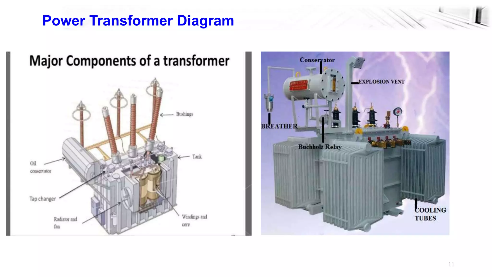
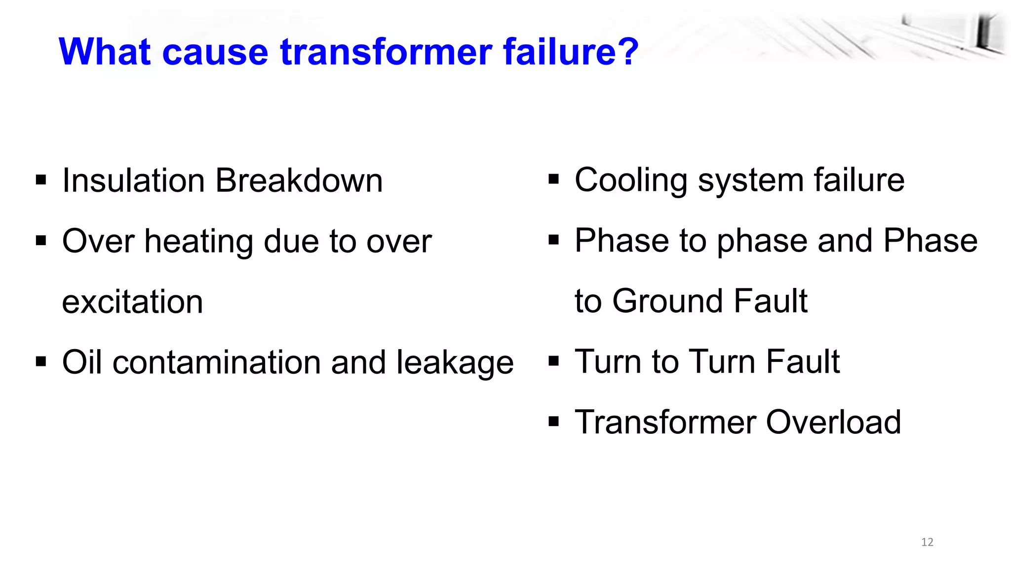
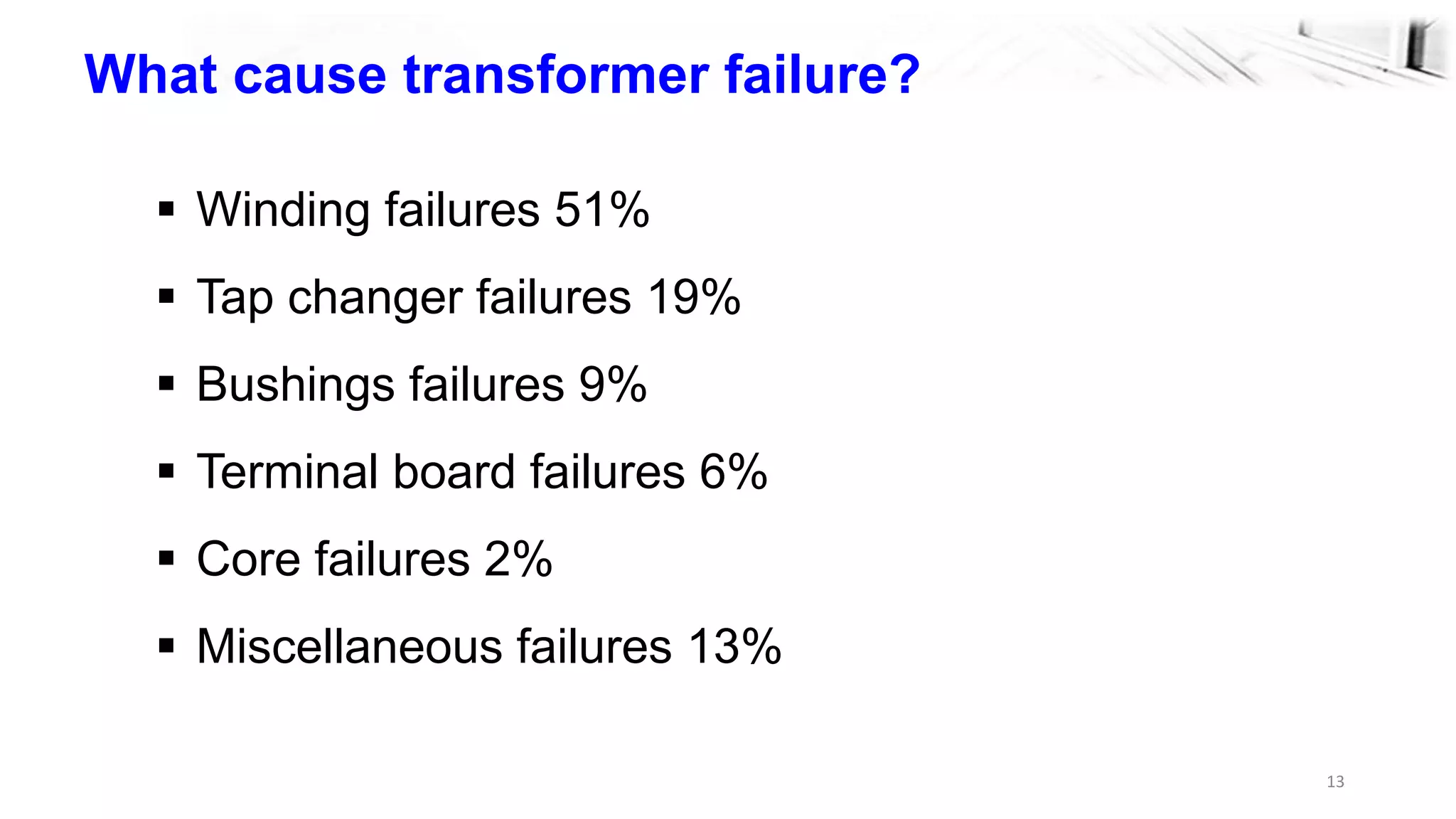
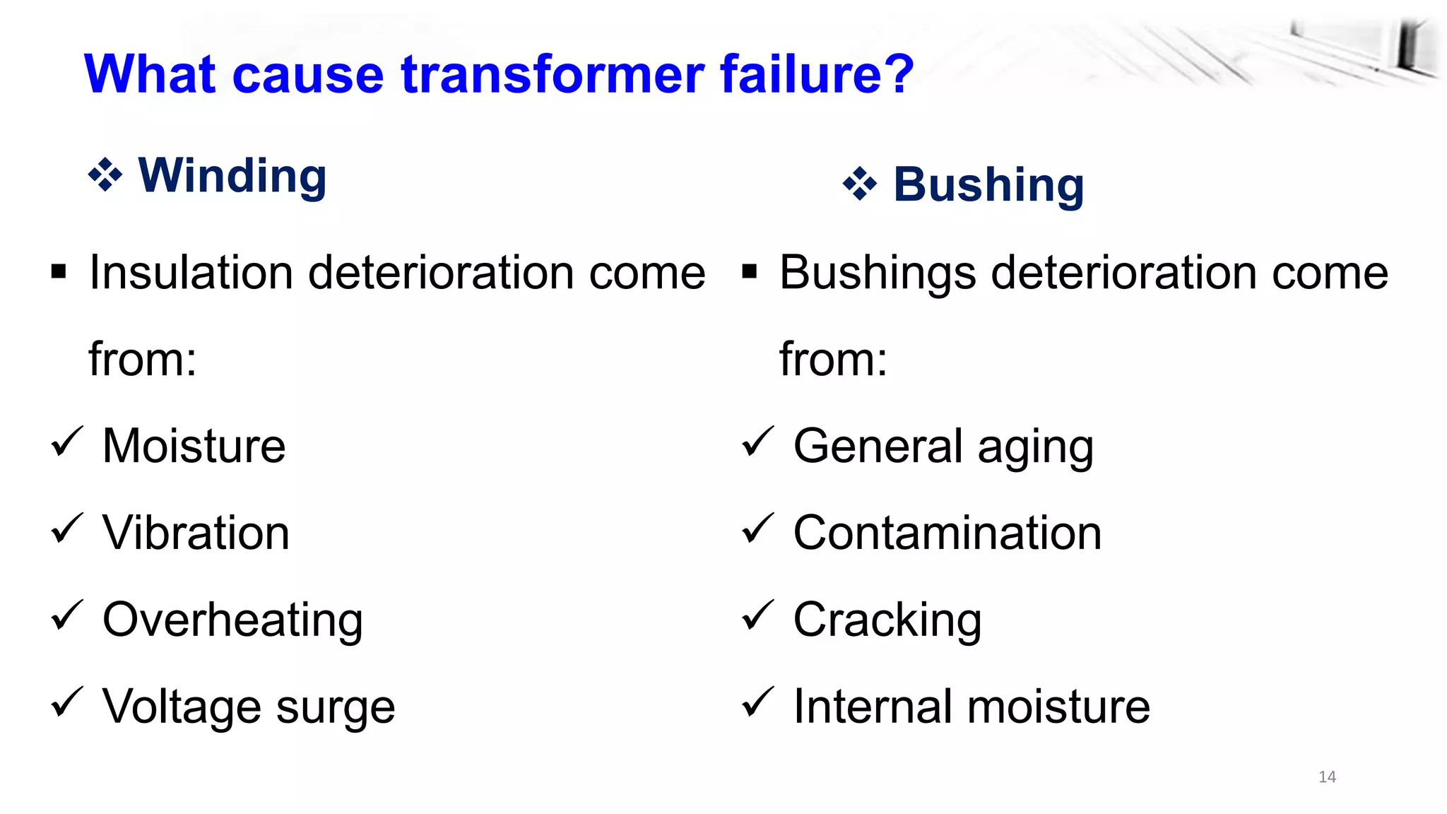
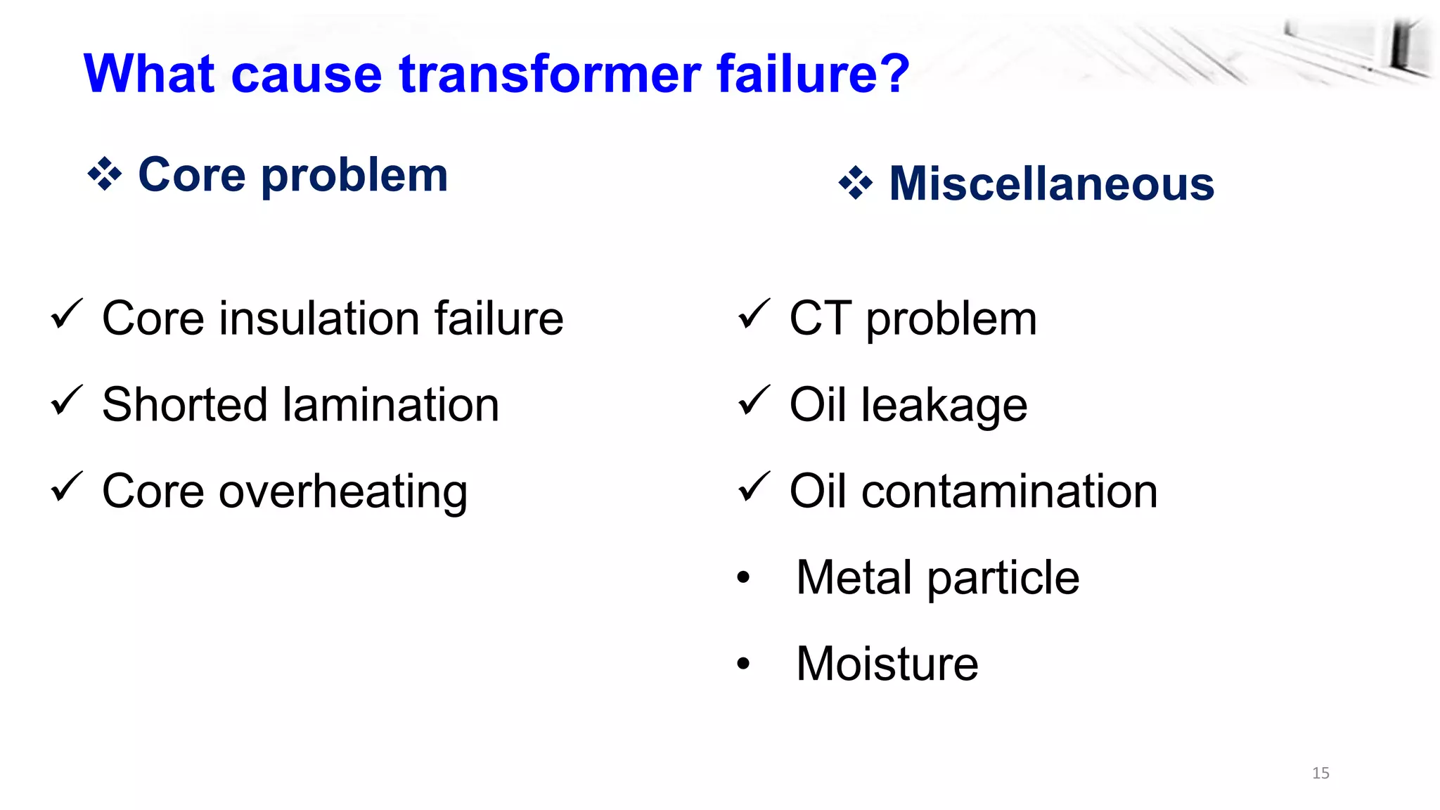

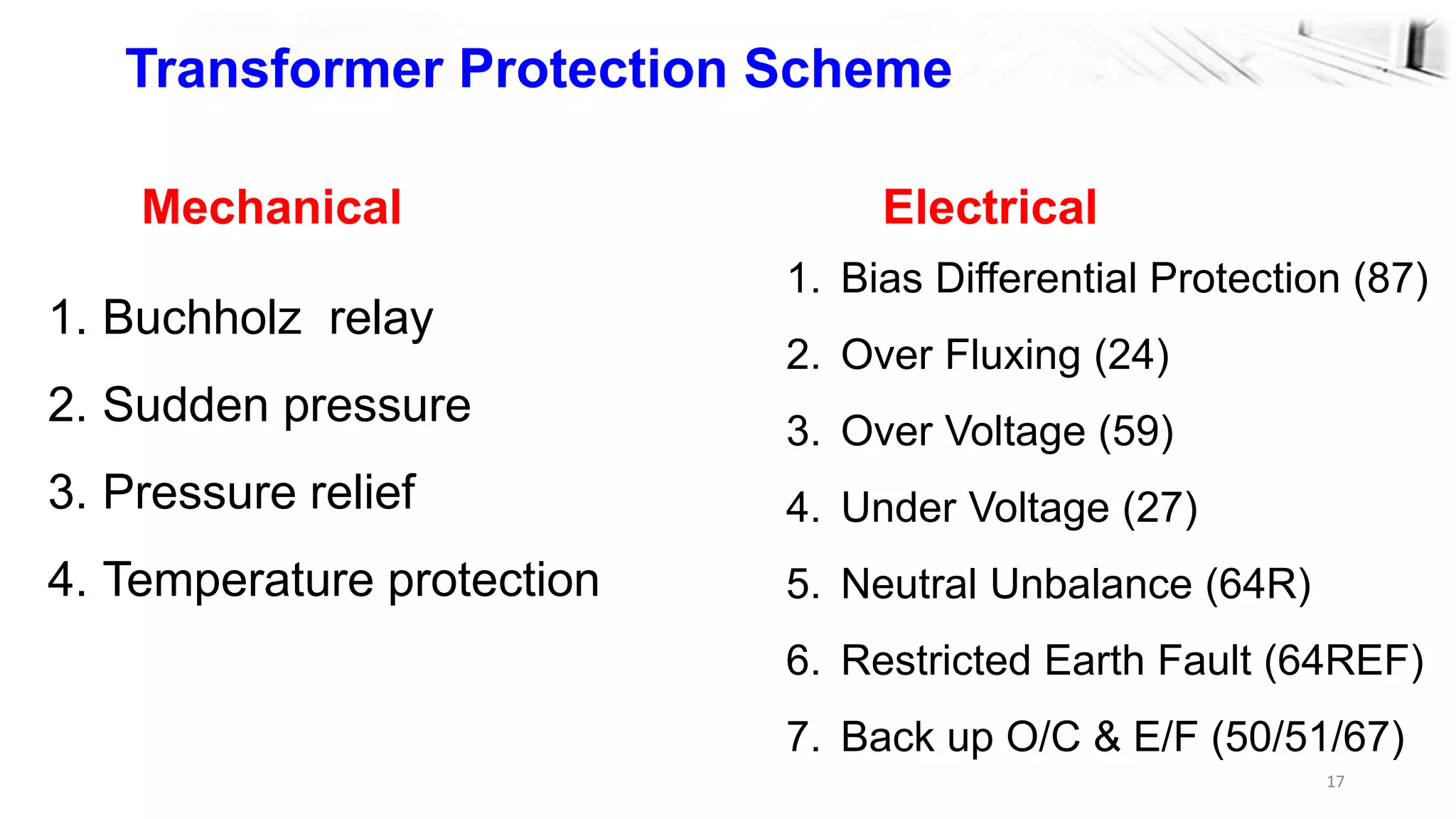
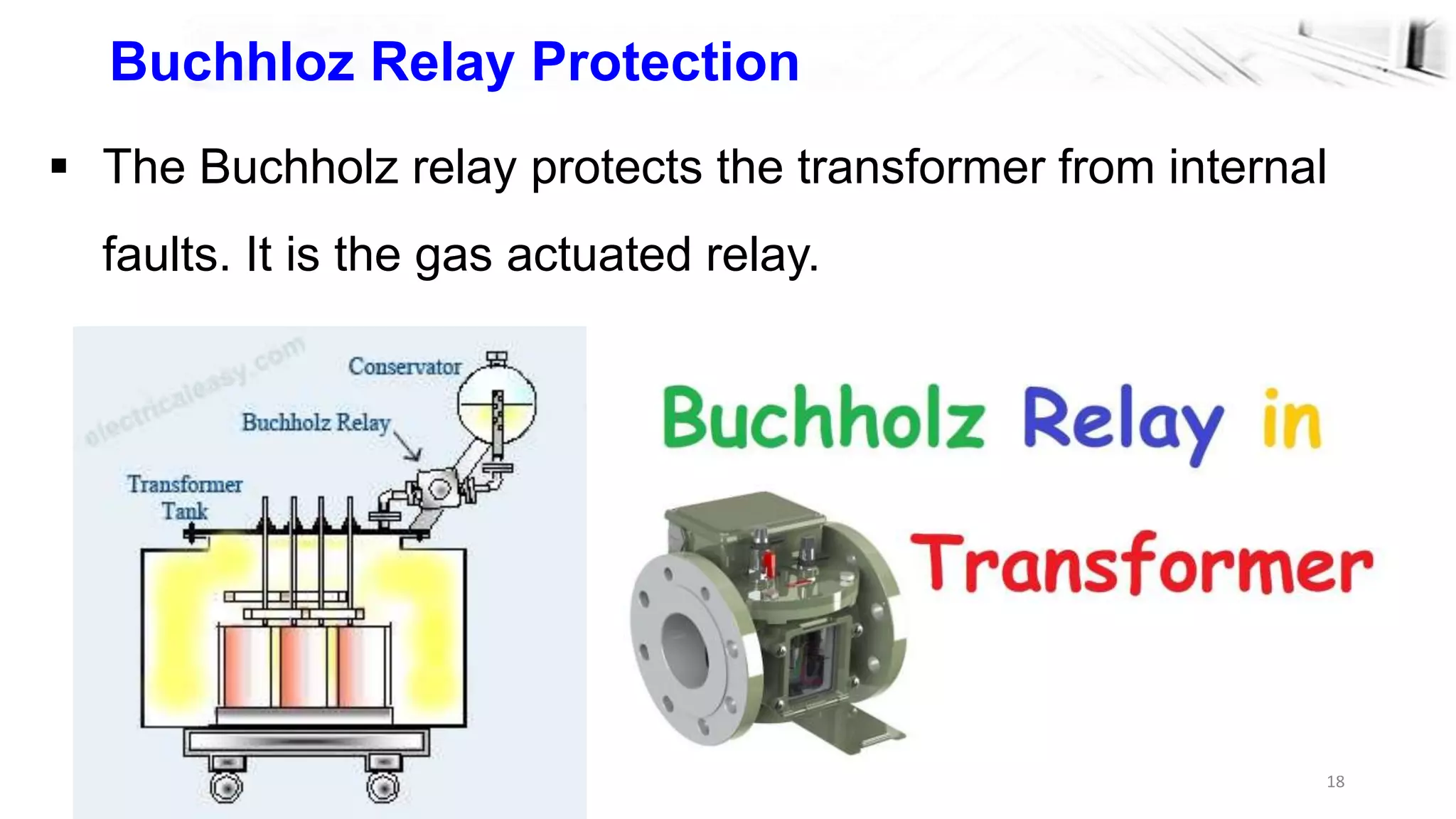
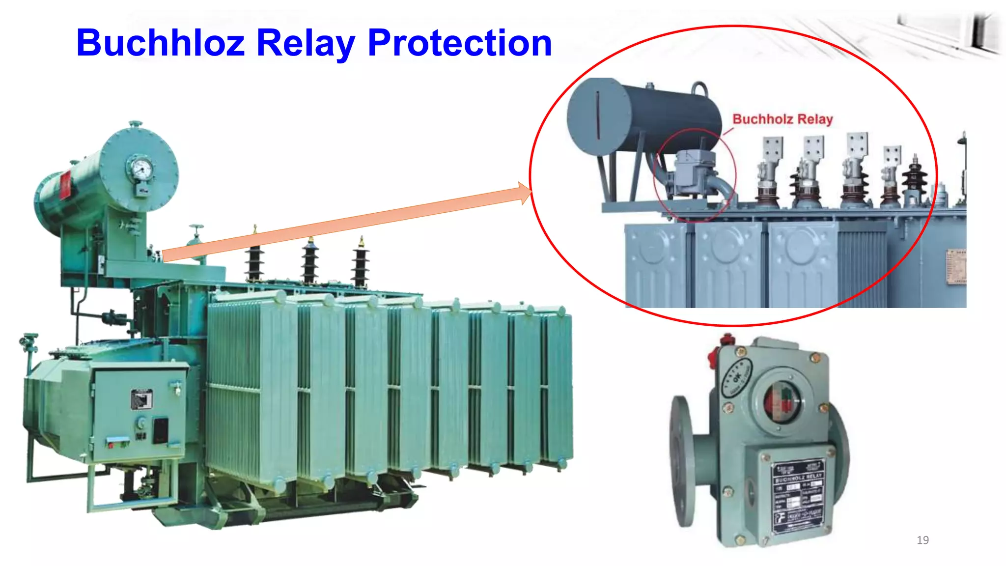
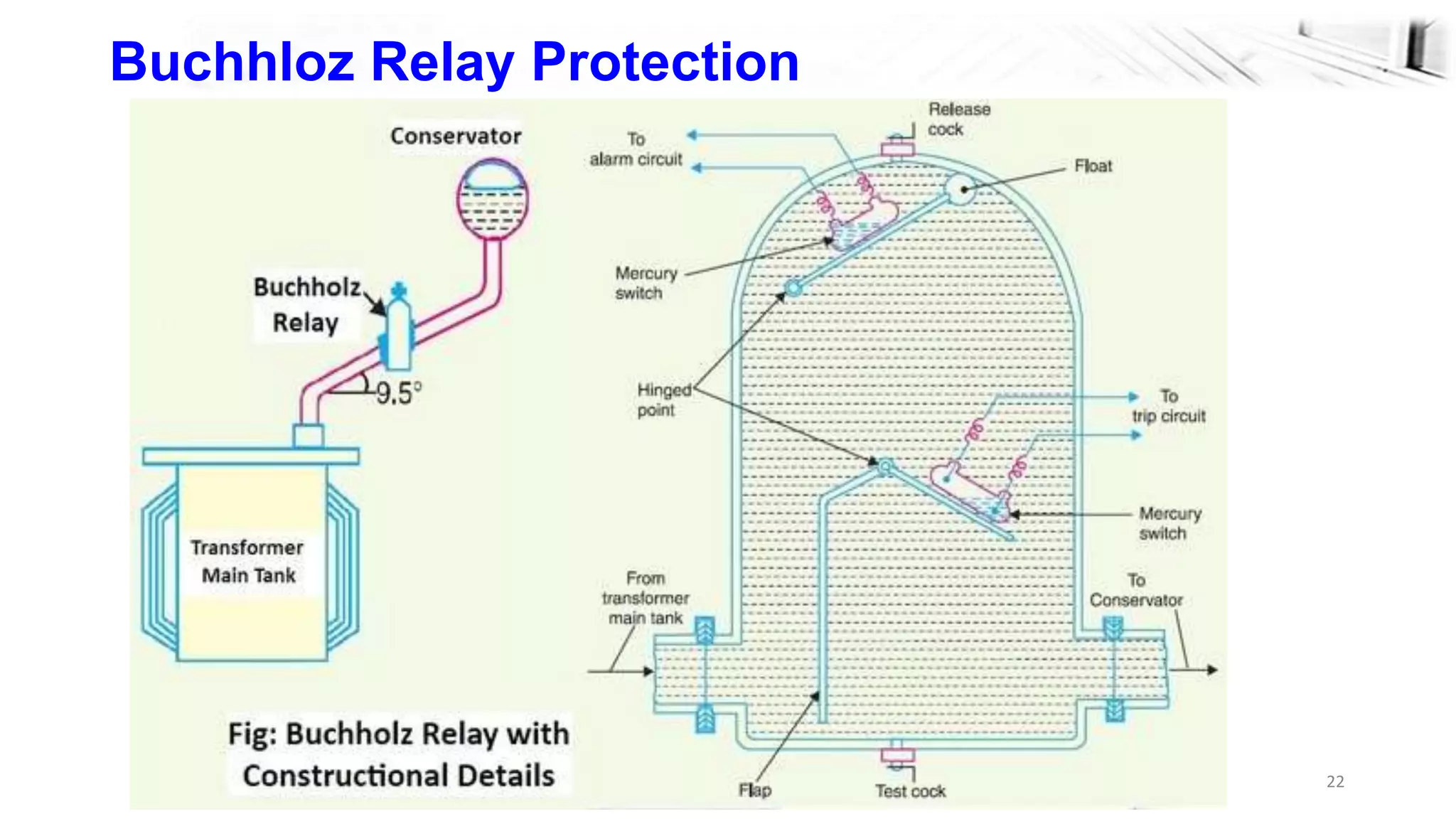
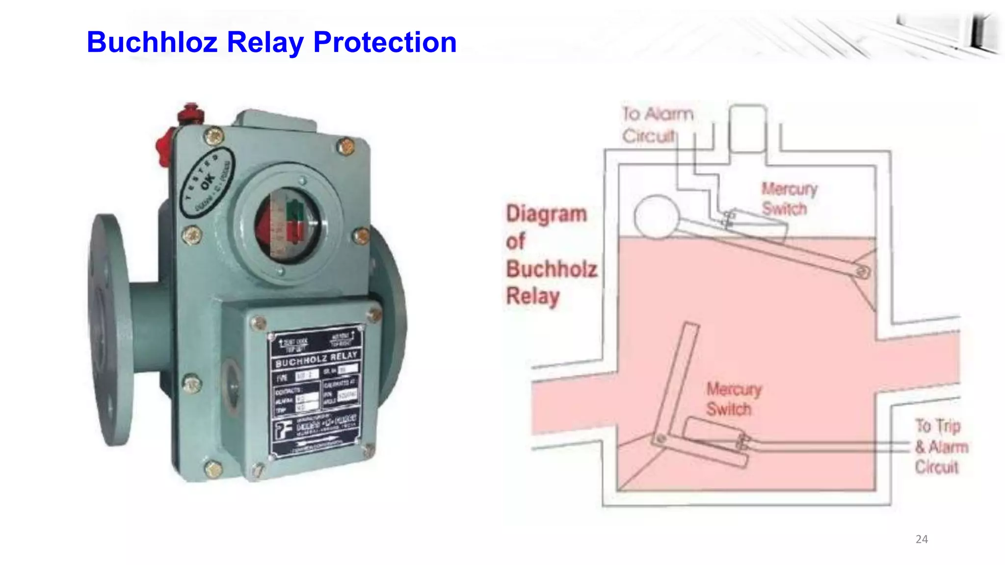


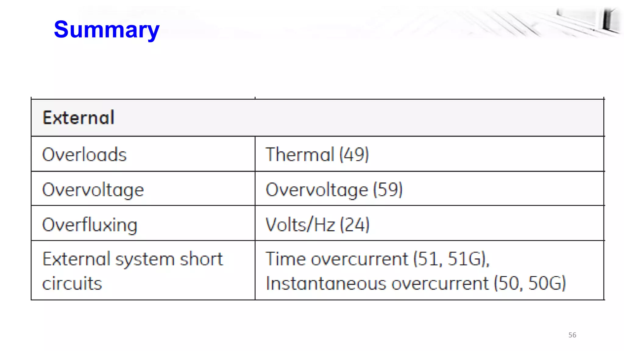

The document discusses power transformer protection, highlighting the importance of safeguarding transformers from faults and overloads to prevent catastrophic failures in electrical systems. It outlines various causes of transformer failure, protection schemes, and specific relays used for protection against different types of faults. Additionally, it explains mechanisms such as the Buchholz relay, pressure relief, and differential protection to ensure the safe operation of transformers within power transmission networks.


