TRANSFORMER PROTECTION
ØThe powertransformer is one of the most important
components in a power-system network.
ØThe consequences of a fault on a Transformer may
be serious unless it is quickly disconnected from the
system.
ØThe reliability of a power transformer depends upon
adequate design, care in erection, proper
maintenance and the provision of certain protective
equipments.
ØTransformers faults can be divided into three main
classes:
(a) Faults in the auxiliary equipment of the transformer
(b) Internal faults in the transformer windings
(c) External faults 1
2.
A. FAULTS INTHE AUXILIARY EQUIPMENT
ØThese faults are usually minor faults.
ØThey do not affect the transformer immediately but, if
allowed to persist, these may develop into faults within the
transformer.
1. Oil Leakage in the Transformer Tank
ØIf the oil leaks from the transformer tank due to some
reason, the oil level in the tank will drop.
Ø In the worst case, the connections to bushings and parts
of the winding will get exposed to air.
ØThis will increase the temperature of the windings.
2
3.
ØIn turn, woulddamage the insulation of the windings.
ØThe conservator tank is provided with an oil-level indicator
having an alarm facility.
ØIf the oil level drops below a predetermined level, the
alarm will ring.
2. Deterioration of Dielectric Strength of Oil
ØThe oil level in the transformer fluctuates because of
variations in the temperature of the oil due to changes
in the load.
ØTherefore the transformer is provided with a
conservator tank. 3
4.
ØThe conservator tankbreathes air through a
dehydrating breather so that moisture does not enter
into the oil.
ØThe entry of moisture would, otherwise, drastically
deteriorate the dielectric strength of the oil.
ØThe atmospheric air first passes through the oil cup
and then through the silica gel.
ØThus moisture gets absorbed in two stages, i.e., in
the oil cup and in the silica gel.
4
5.
3. Failure ofVentilation System
ØTemperature of oil and windings will increase due to
failure of the cooling system of the transformer.
ØCooling system may fail due to blocking of the radiator,
failure of oil pump/pumps or failure of some/all fans.
ØAn oil-temperature indicator with alarm and trip facilities
with winding-temperature indicator are used to avoid
damage to the transformer by overheating.
ØNormal operation of the oil pump can also be monitored
by an oil-flow indicator.
5
6.
4. Weakening ofInsulation Between Laminations
of Core and Core-bolt Insulation
ØWeakening of insulation between laminations of the core
and core bolt will result in increased eddy current losses
and hence rise in temperature of the core.
ØThis may, consequently, lead to failure of the insulation of
the winding causing a major fault.
5. Improper Joints or Connections
ØThe local heating generated by improper joints or
connections may slowly lead to a deterioration of the oil if
the joint is oil-immersed.
ØThe oil-temperature indicator and/or winding temperature
indicator (both with alarm contacts) can be used to
indicate such problems.
ØGas-operated relays can also be used to sound an alarm
and actuate the trip circuit if the condition calls for it.
6
7.
6. Inter-turn Faults
ØIfonly a few turns of any of the windings are shorted,
the electrical relays will not operate but the local
overheating caused by the fault may slowly
deteriorate the insulation and, consequently, a major
fault may occur.
ØFor all such incipient faults, an oil-level indicator, oil-
temperature indicator, winding-temperature indicator
and gas-operated relays are used as protective
devices. 7
8.
B. INTERNAL FAULTS
ØWhenthe insulation between windings and between the
winding and the core fails, it is termed an electrical fault.
ØThere can be phase-to-phase faults, phase-to-ground faults,
faults between H.V. and L.V windings or inter-turn faults.
ØThe faults occurring in oil can be sensed by gas actuated
relays but the faults outside the oil have to be taken care of by
electrical relays only.
ØFor heavy electrical faults inside the oil, gas actuated relays
are not entirely relied on.
8
9.
ØThese faults candevelop due to overload, loose
connections or over-voltages resulting from lightning
or switching surges and also as a consequence of
minor faults.
ØThese electrical faults have to be cleared by the
transformer-protection scheme using different types of
relays.
9
10.
C. EXTERNAL FAULTS
ØThroughfaults can occur due to overloads or external
short-circuits.
ØIf such faults occur, the transformer must be
disconnected after allowing predetermined time during
which other protective gear should be operated.
ØA sustained overload condition can be detected by
thermal relays which gives an alarm.
ØFor the external short-circuit condition, time-graded
overcurrent relays are usually employed.
10
11.
GAS-OPERATED RELAYS
ØThe minorfaults, create local heat which causes the
oil to decompose into gases that rise through the oil
and accumulate at the top of the transformer.
ØWhenever a fault in a transformer develops slowly,
heat is produced locally which begins to decompose
solid or liquid insulating materials and thereby leading
to the production of inflammable gases.
ØSuch conditions can be detected by gas-actuated
relays.
11
12.
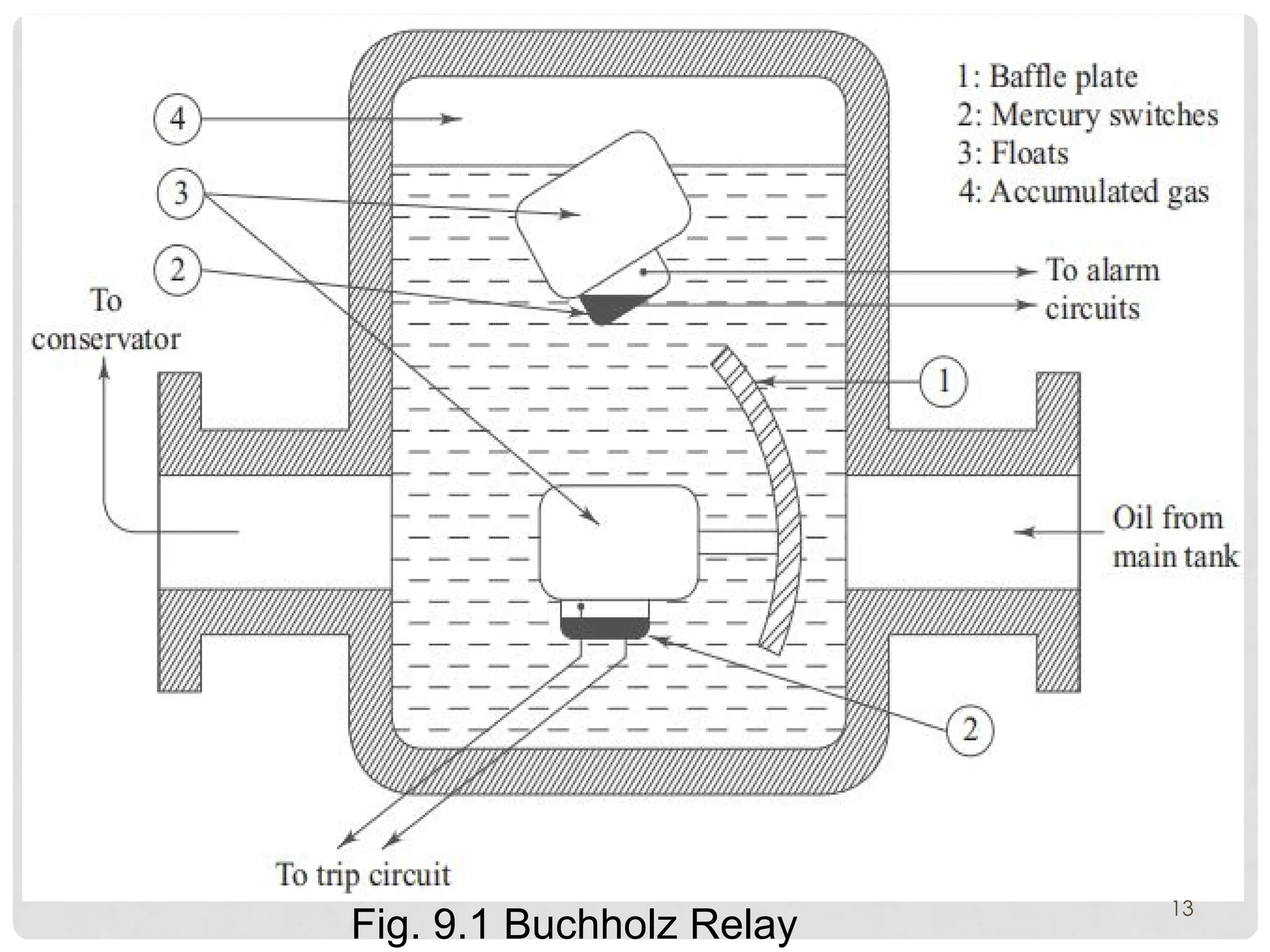
BUCHHOLZ RELAYS
ØThe Buchholzrelay operates an alarm when a specified
amount of gas has accumulated.
ØThis type of relay can only be fitted to the transformers
which are equipped with conservator tanks as it is installed
in between the main tank and the conservator tank, i.e., on
the pipe connecting the two.
ØConstruction: The relay consists of an oil-tight container
having two internal floats which operate and actuate mercury
switches which in turn are connected to the external alarm or
tripping circuits.
12
ØFor an incipientfault within the transformer, gas is generated
in small bubbles which pass upwards through the relay to the
conservator tank.
ØIn the process of passing through the relay, they are trapped
in the housing of the relay and the oil level falls.
ØThe upper float is now no longer under the upward thrust and
under the action of the counter-weight attached to it,
ØThen the float falls down in such a manner so as to tilt the
mercury switch.
ØThen mercury switch shorts the two contacts and the alarm
circuit is completed hence thealarm warning. 14
15.
ØFor a seriousfault within the transformer, the gas generation
is in much larger quantity and the oil is displaced in the relay
by the gases, towards the conservator tank, with the result that
the baffle plate is deflected by the force of oil and gas mixture
tilting the lower float, and the mercury switch.
ØThe trip coil of the transformer breaker, gets energised and the
breaker isolates the transformer from the supply.
ØThe relay is also useful in indicating any loss of oil that a
transformer might suffer, as the loss of oil will cause the oil
level to drop in the relay.
ØThen the top float will indicate the condition by shorting the
alarm contacts.
15
16.
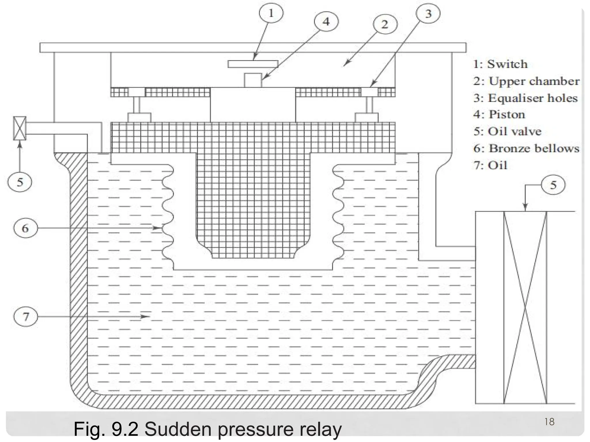
SUDDEN PRESSURE RELAY
ØWithtransformers having a gas cushion instead of a
conservator tank, the tripping unit of the Buchholz
relay is not applicable.
ØHence a sudden pressure relay is used as shown in
Fig. 9.2.
ØThe relay operates on the basis of the rate of the rise
of pressure.
ØIt has a diaphragm which is deflected by a
differential oil pressure. 16
17.
ØIn some relays(Fig. 9.2) the diaphragm is not directly
immersed in the transformer oil but inside the metal
bellows full of silicon oil.
ØThe bellows are immersed in the transformer oil.
ØThis prevents incorrect operation under mechanical
shocks and vibrations.
17
OVERCURRENT PROTECTION
ØTransformers areprovided with overcurrent
protection against faults when the cost of
differential relays cannot be justified.
ØHowever, overcurrent relays are provided in
addition to differential relays to take care of
through faults and as a back-up to differential
protection.
19
ØWhile selecting theovercurrent protection the
following aspects need consideration:
1. IDMT relays are not
affected by the current inrush as they have enough time
lag. Instantaneous overcurrent units should be set
higher to avoid mal-operation.
ØThis setting is usually high enough to override
magnetising inrush current.
21
22.
2. Primary full-loadcurrent should be considered
while setting the overcurrent relay. The plug-setting
of the IDMT overcurrent relay is generally selected as
125% of the transformer rating to take care of normal
overloads.
3. The same set of current transformers cannot be
used for both differential protection and overcurrent
protection, as the CT requirements for these protection
schemes are different.
22
23.
R E ST R I C T E D E A R T H - F A U L T
PROTECTION
ØThe restricted earth-fault protection, which employs
the principle of circulating current differential
protection, responds to the internal earth-faults in any
one of the windings (star-connected) of the
transformer.
ØFor external faults, the time graded earth-fault relays
are used.
ØT h e r e s t r i c t e d e a r t h - f a u l t r e l a y o p e r a t e s
instantaneously for an internal fault.
23
24.
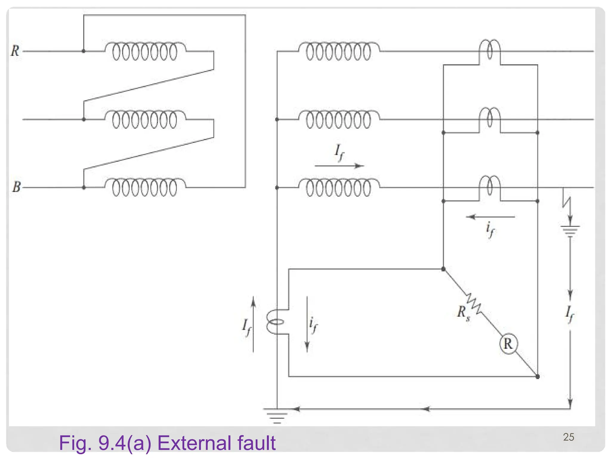
ØFig. 9.4(a) and(b) explains the principle of a restricted
earth-fault protection.
ØFig. 9.4(a) shows the condition of an external earth-
fault.
ØFig. 9.4(b) shows the current flow through the relay in
case of an internal fault.
ØIt is obvious in Fig. 9.4(a) the fault current circulates in
the pilot wires and no current passes through the relay.
ØHence, the relay does not operate.
24
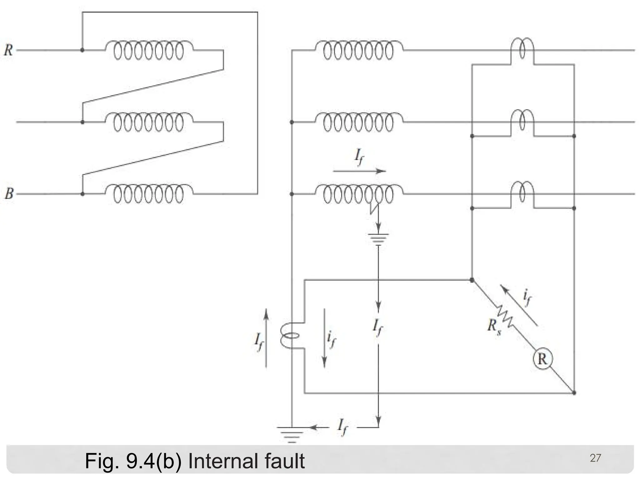
ØFor an internalfault Fig. 9.4(b) the fault current ��
flows in the neutral CT only and not in the line CTs.
ØThe CT secondary current if flows through the relay and
the relay operates instantaneously if the current is more
than the pick-up setting of the relay.
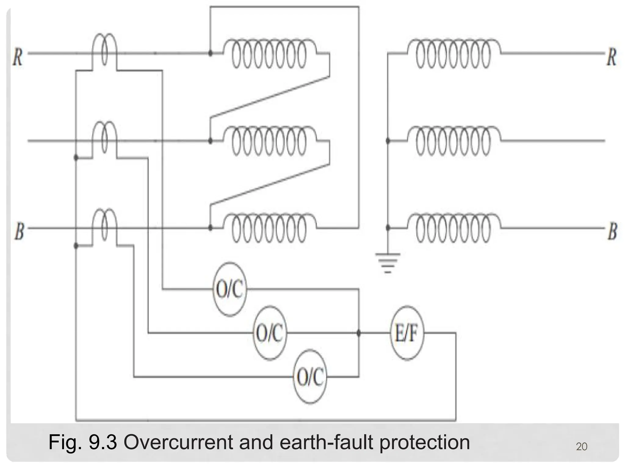
ØThe earth-faults on the delta side of the transformer will
be taken care of by an earth-fault element as shown in
Fig. 9.3.
26
DIFFERENTIAL PROTECTION
Ø Problemsin Application of Differential Protection
1. The transformer voltage rating is different for
primary and secondary.
vVoltage rating of CTs used in primary and
secondary are different.
vIt is quite possible that the CTs on both the sides
may be from different manufacturers.
vUnder these circumstances, the CTs on both
sides are usually not identical with regard to their
saturation characteristics.
28
29.
29
vThese non-identical CTsmay cause high spill
current to flow through the relay in case of heavy
external fault.
vThis avoided by using biased differential relay.
2. The full-load currents of the transformers on
primary and secondary sides are different.
vThe ratio of the CTs used on both the sides, have to
be so selected that the pilot wire currents are same
on both the sides.
30.
vCTs of standardratios are employed in conjunction
with interposing CTs.
3. The current transformers may have small ratio
errors at the normal rated current.
vBut during external short-circuits, the CT primary
currents are unduly large.
vThe ratio errors of the CTs on either sides differ
during such conditions due to:
30
31.
(i) inherent differencein CT characteristic,
(ii) unequal dc components in the short-circuit
currents.
vA biased differential relay can avoid unwanted
operation of the relay under such circumstances.
4. Inherent phase-shift of currents in the
transformers: The primary and secondary currents are
not in phase in three-phase transformers connected in
delta-star.
31
32.
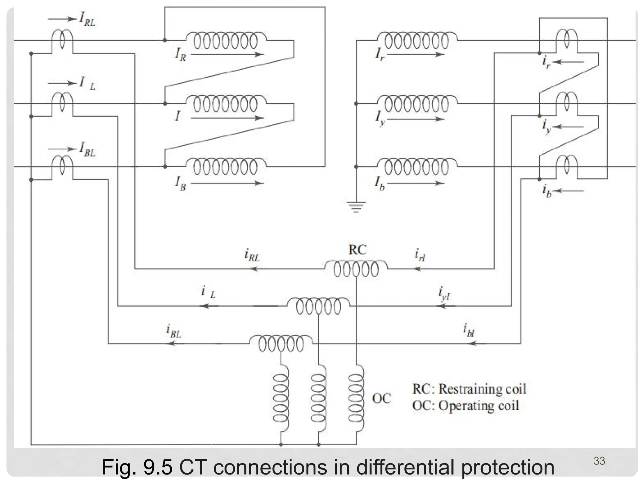
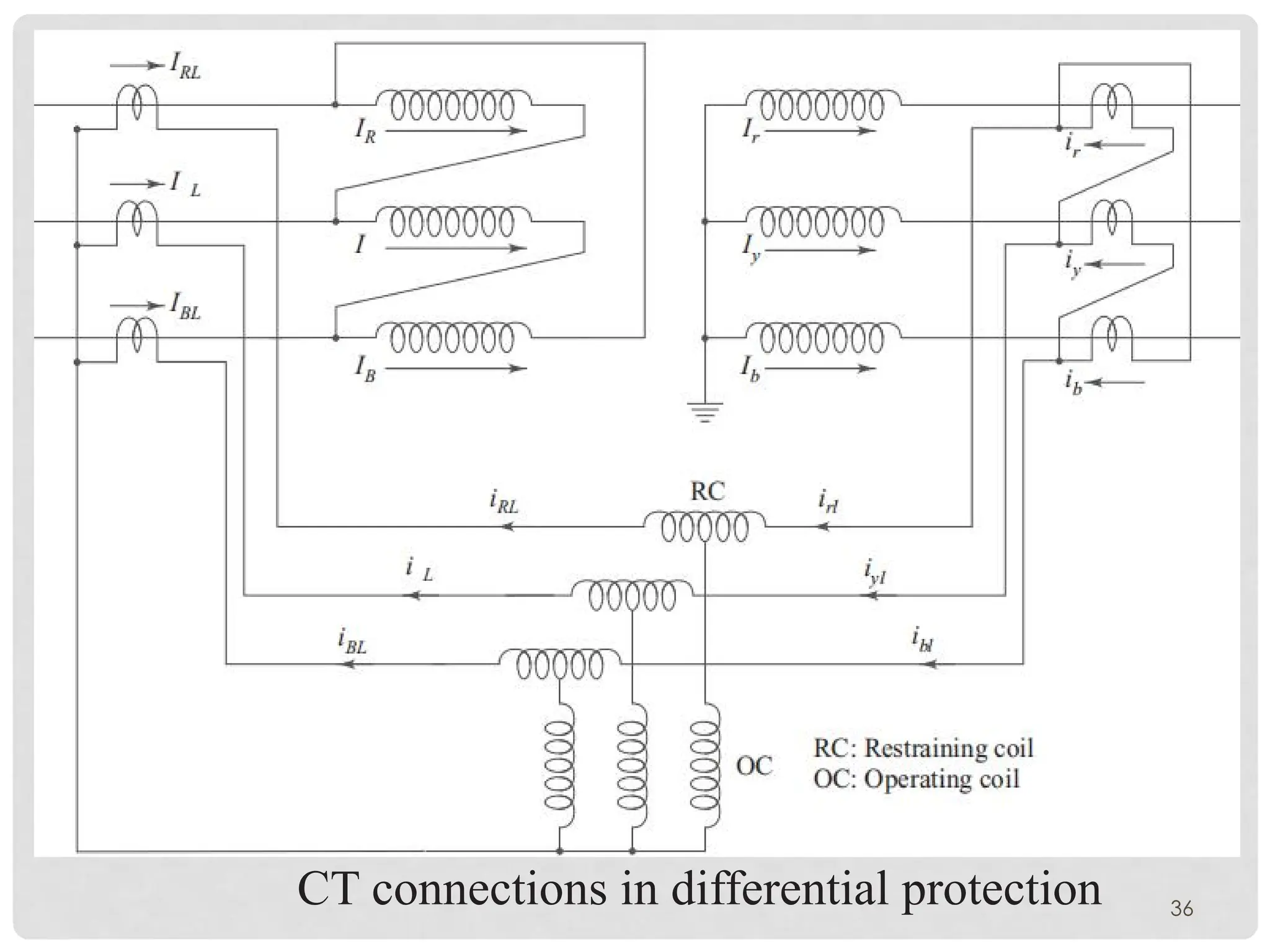
ØTo make thescheme immune to secondary external
earth-faults, the CTs on the star side should once
again be connected in delta.
ØThe two pilot currents have to be taken care of by
proper connection of CTs, on both the sides.
ØCTs on the delta side of the transformer are
connected in star and those on the star side of the
transformer in delta as shown in Fig. 9.5.
32
5. CT RatioErrors: The CTs have some allowable
ratio errors depending on the class of CTs used.
ØThe worst case is experienced when the errors of the
CTs on the primary and secondary sides are
cumulative.
ØIn such a case the spill current will flow through the
operating coil of the relay, making it to operate
particularly at a high through fault current.
ØBiased winding (restraining winding) of the relay can
avoid unwanted tripping of the relay in such a case.
34
35.
6. TAP-CHANGING
Øtransformers arealways provided with the tappings to regulate
the output voltage as required by the loading conditions.
ØThe ratios of the CTs (used for differential protection) on both
sides are selected on the basis of a normal tap.
ØOnce the tap is changed, the pilot wire currents on both sides
will not be the same.
ØSpill current, will flow through the operating coil of the relay.
ØIt tend to operate the relay, particularly for high through fault
currents.
ØBiased differential relay can avoid such uncalled tripping.
35
7 . MA G N E T I S I N G I N R U S H C U R R E N T O F T H E
TRANSFORMER
ØAny condition that calls for an instantaneous change in flux
linkages in a power transformer will cause large magnetising
currents to flow, which will produce an operating tendency in a
differential relay.
ØThe largest inrush and greatest relay-operating tendency occur
when a transformer is not connected to the load and is
energised.
ØConsiderably smaller but still troublesome inrushes occur
when a transformer with a connected load is energised or
when a short circuit occurs or when it is disconnected.
37
38.
ØThe occasional trippingbecause of inrush when a
transformer is energised is objectionable because it
delays putting back the transformer into service.
ØThe biased winding cannot take care of this problem
because the pick-up ratio
�1 − �2
�1 + �2
2
will be very high
(of the order of 200%) and the bias setting is usually
15 – 50%.
ØIf the setting is increased to a value higher than 50%,
the differential relay will become highly insensitive to
in-zone faults.
38
39.
PROTECTION AGAINST OVERFLUXING
ØThetransformers in generating stations need protection
against the risk of damage, which may be caused when they
are operated at flux density levels significantly greater than the
designed values.
ØThese conditions are most likely to arise when the unit is on
open circuit with the generator field energised; the speed of
the machine is considerably below the synchronous speed and
the regulator is trying to bring the voltage to the normal rated
value.
39
40.
ØThis may resultin an unduly large value of �� and
hence a flux.
ØThe basic operating principle of the relay used for the
protection against overfl uxing is to provide an ac
voltage proportional to the �� ratio.
ØWhen the peak of the ac signal exceeds the dc
reference, the relay starts operating.
ØThe relay is a time-lagged relay
40
41.
PROTECTION AGAINST OVERHEATING
ØOverheatingof the transformer winding or oil can be caused
due to; overload, failure of cooling fans or oil pumps, blocking
of radiator, oil leakage, electrical short-circuiting of laminations
or core bolt insulation failure, dry joints or connections, overfl
uxing, etc.
ØTemperature transducers like Resistance Temperature
Detectors (RTDs) or thermocouples are embedded near each
winding.
Ø When the measured temperature increases above a safe
limit, an audible alarm is issued.
41
42.
ØIf corrective stepsare not executed within a short
time then the trip signal to the circuit breaker is given
after a certain value of temperature is reached.
ØOther overheating protection include:
A. Oil Thermometer
ØIn oil-filled transformers, an oil thermometer is
commonly used as a semi-effective device.
ØIt is provided with alarm contacts connected to give a
warning to the operator in the control room whenever
there is an abnormally high oil temperature. 42
43.
ØIt is locatedso as to monitor the temperature of the
hottest area in the oil in the transformer tank.
ØThis thermometer is sometimes also used to start
cooling fan motors to extend the loading capability of
the transformer.
ØAs the transformer oil has a higher time constant, this
thermometer which measures oil temperature is not
dependable as a fault-detecting unit.
43
44.
B. WINDING THERMOMETER
ØInthis thermometer, the bulb is embedded near the winding. Hot
circulating oil surrounds this thermometer bulb.
ØA small heater is connected across the CT secondary to heat the
bulb.
ØThus, the heat transferred to the bulb is dependent on the load
current as well as the temperature of oil near the winding.
ØThe thermometer is designed and adjusted to match its
characteristic with the heating curve of the transformer winding.
ØThe measurement of a winding thermometer is nearer to the
actual thermal condition of the transformer than that of the oil
thermometer. 44
45.
TRANSFORMER PROTECTION USINGA
NUMERICAL RELAY
ØThe recent practice of protecting a power
transformer is to use a comprehensive numerical
relay.
ØThese relays have all the protections such as:
Differential Protection, Restricted Earth-fault
Protection, Back-up Overcurrent Protection, Thermal
Overload Protection etc.
45