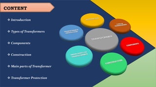
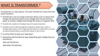
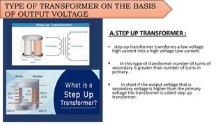
WELCOME
Koradi Training Center (KTC),Nagpur
Topic - TRANSFORMER PROTECTION
Presented by:
 Pranay Ingale
 Atish Verma
 Vedant Thakre
 Shweta Kohale
 Pallavi Mathane
 Aniket Awate
 Harsh Sonkuwar
 Akshay Narnavre
CONTENT
 Introduction
 Types of Transformers
 Components
 Construction
 Main parts of Transformer
 Transformer Protection
A transformer is a static device. The word 'transformer' comes form the
word 'transform’.
 Transformer is not an energy conversion device, but it is device that
changes AC electrical power at one voltage level into AC electrical
power at another voltage level through the action of magnetic field.
 Transformer works on Faraday's law of mutual induction
 Faraday's law of electromagnetic induction states that, when a
change takes place in the magnetic flux which is linked with a circuit,
an electromotive force current will induce in the circuit.
 It can be either to step-up or step down.
 Commonly used transformer type, depending upon voltage they are
classified as:
-Step-up Transformer
-Step down Transformers
WHAT IS TRANSFORMER ?
TYPE OF TRANSFORMER ON THE BASIS
OF OUTPUT VOLTAGE
A.STEP UP TRANSFORMER :
 step up transformer transforms a low voltage
high current into a high voltage Low current.
 In this type of transformer number of turns of
secondary is greater than number of turns in
primary .
 In short if the output voltage that is
secondary voltage is higher than the primary
voltage the transformer is called step up
transformer.
 step down transformer transforms
a high voltage low current into a
low voltage high current.
 In this type of transformer
number of turns of primary is
greater than number of turns in
secondary.
In short if the output voltage that
is primary voltage is higher than
the secondary voltage the
transformer is called as step down
B.STEP DOWN TRANSFORMER
COMPONENTS (PARTS OF TRANSFORMER)
 Breather
 Radiators and fans
 Explosion vent
Breather
 Radiators and fans
 Explosion vent
 Tap changers
 Buchholz relay
 Temperature Gauge
 Core
 Winding
 Insulation
 Tank Core
 Winding
 Insulation
 Tank
 Terminal and
bushings
 Transformer oil
 Oil Conservators
CONSTRUCTION
• The transformer mainly consists of the Magnetic
circuit, electric circuit, dielectric circuit, tanks,
and accessories.
• The main elements of the transformer are
the primary and secondary windings and
the steel core.
• The core of the transformer is made up of silicon
steel in order to provide a continuous magnetic
path.
• Usually, the core of the transformer is laminated
for minimizing the eddy current loss.
MAIN PARTS OF TRANSFORMER
 TANK
• Main tank is the robust part of transformer that
serves mainly two purposes:
• It protects core and windings from the external
environment and provide housing for them.
• It is used as a container for transformer oil and
provides support for all other external accessories of
the transformer.
• Main tank of the transformer are made up of
fabricated rolled steel plates. They are provided with
lifting hooks and inbuilt cooling tubes. In order to
minimize the weight and stray losses, aluminum
sheets are also being used instead of Steel plates.
RADIATOR AND FANS
• Since power losses in the transformer
are dissipated in the form of heat. So
a cooling arrangement is required for
the power transformer.
• Dry-type transformers are generally
natural air-cooled. But when we talk
about oil-immersed transformers
then several cooling methods are
used depending upon kVA rating,
power losses, and level of cooling
required.
• Hence to provide proper cooling,
radiators and fans are installed on the
main tank of the power transformer.
Radiators are also called cooling
tubes. In a large power transformer,
forced cooling is achieved with the
help of cooling fans fitted on the
radiator.
• The Conservator Tank of a transformer is defined
simply as a cylindrical tank mounted on the roof
of the transformer main tank. It is used to provide
enough space for the oil in the transformer to
spread after heating.
• The main function of the conservator Tank
• When the transformer is loaded and when the
ambient temperature rises, make the volume of
oil inside the transformer increase. A conservator
tank of the transformer supplies adequate space
to this expanded transformer oil. It also is
designed as a reservoir for transformer insulating
oil.
CONSERVATOR TANK
The function of transformer oil is
to provide insulation between
windings as well as cooling due
to its chemical properties and
very good dielectric strength
Core balance Current Transformer
(CBCT)It dissipates the heat
generated by the core and windings
of a transformer to the external
environment. When the windings of
transformer gets heated due to flow
of current and losses, the oil cools
down the windings by circulating
inside the transformer and transfer
heat to the external environment
through its cooling tubes
Hydro-carbon mineral oil is used
as transformer oil and acts as
coolant. It is composed of
aromatics, paraffin,
naphthene's, and olefins.
 TRANSFORMER OIL
 INSULATION
• To avoid any electrical activity between any part of insulation is used ,
• An ideal insulating material should posses some property
1.Should have high value of resistance
2.Should have high melting point
3.It should be cheap and flexible
4.Should not consume any power
5.Should not detoriate
This Photo by Unknown Author is licensed under CC BY
• Breather is a cylindrical container filled with
silica gel and directly connected with the
conservator tank of the transformer.
• The main function of the breather is to
supply moisture-free fresh air to the
conservator tank during the expansion and
contraction of transformer oil.
• This is because the transformer oil when
reacting with moisture can affect the
insulation and cause an internal fault in a
transformer.
• That's why the air entering in conservator
tank should be moisture free for better life
of transformer oil.
 BREATHER
• The main function of the tap changer is
to regulate the output voltage of
transformer by changing its turns ratio.
There are two types of tap changers.
• 1. On-load tap changer:- in an on-load
tap changer, tapping can be changed
without isolating the transformer from
the supply. Hence it is capable to
operate without interrupting the power
supply.
• 2. Off-load tap changer:- in off-load tap
changer, the transformer needs to
isolate from supply to change its
tapping (turns ratio).
• An automatic tap changer is also
available.
 TAP CHANGER
 Common Types of Transformer Protection
Overheating protection
1.Overcurrent protection
Earth fault protection
Differential Protection of Transformer
Buchholz (Gas Detection) Relay
Over-fluxing protection
Circuit Breakers
Lightning arrestor
Grounding transformer
Other Protections
Overheating protection
Transformers overheat due to the overloads and
short circuit conditions. The allowable overload and
the corresponding duration are dependent on the
type of transformer and class of insulation used for
the transformer.
Higher loads can be maintained for a very short
amount of time if it is for a very long, it can damage
the insulation due to temperature rise above an
assumed maximum temperature.
 The temperature in the oil-cooled transformer is
considered maximum when its 95*C, beyond which
the life expectancy of the transformer decreases and
it has detrimental effects in the insulation of the
wire.
Overcurrent protection
The overcurrent protection system is one of the earliest
developed protection systems out there, the graded overcurrent
system was developed to guard against overcurrent conditions.
power distributors utilize this method to detect faults with the
help of the IDMT relays. that is, the relays having:
1.Inverse characteristic, and
2.Minimum time of operation.
The capabilities of the IDMT relay is restricted. These sorts of
relays have to be set 150% to 200% of the max rated current,
otherwise, the relays will operate for emergency overload
conditions.
Differential Protection of
Transformer
The Percentage Biased Current Differential Protection
is used to protect power transformers and it is one
of the most common transformer protection
schemes that provide the best overall protection.
 These types of protection are used for transformers of
rating exceeding 2 MVA.
Earth Fault Protection (Restricted)
A very high fault current can flow when a fault occurs
at the transformer bushing. In that case, the fault
needs to be cleared as soon as possible. So, that is why
the relay is named Restricted earth fault protection
relay.
This relay has three phases, if a fault occurs, they will
have three components, the positive sequence
components, the negative sequence components,
and the zero sequence components.
Buchholz (Gas Detection) Relay
The Buchholz relay is fitted in between the
main transformer unit and the conservator
tank when a fault occurs within the
transformer, it detects the resolved gas with
the help of a float switch.
The main purpose of Buchholz Relay is to give
the protection to a transformer from the
different faults happening in the transformer
like short circuit, core etc.
Over-fluxing protection
 transformer is designed to operate at a fixed flux level exceed
that flux level and the core gets saturated, the saturation of the
core causes heating in the core that quickly follows through the
other parts of the transformer that leads to overheating of
components, thus over flux protection becomes necessary, as it
protects the transformer core.
To protect the transformer from over-fluxing, the over-
fluxing relay is used. The over-fluxing relay measures the
ratio of Voltage / Frequency to calculate the flux density in the
core.
Vv
OTHER PROTECTIONS ARE -
CIRCUIT BREAKERS
What is CIRCUIT BREAKER
The circuit breaker is a switching device which also
offers protection by tripping & cutting off the
supply to load in case of fault. Primarily the circuit
breakers are used for switching of different kinds of
load in Industries, Buildings, Commercial
Complexes, `and Hotels, etc.
 NEED OF CIRCUIT BREAKER
Many kind of abnormal conditions are there which
exist in our electrical system that have the potential
to damage the circuit & its components. These
conditions are defined as ‘FAULTS’.Further, fault is
categorized as mentioned below:
Overload
Short Circuit
Earth
TYPES OF CIRCUIT BREAKER
VACUUM CIRCUIT BREAKER (VCB)
Vacuum Circuit Breaker or VCB is used for Medium Voltage
applications. In VCB the contacts operation & arc
quenching takes place inside bottles where Vacuum is
present.
SF6 CIRCUIT BREAKER
SF6 circuit breakers are also used mainly in medium
voltage applications. In this breaker SF6 gas is used
for arc quenching due to its ability of quenching the
arc very efficiently.
SF6 Breakers being highly efficient in arc quenching
are still not preferred much as SF6 being a poisonous
gas, is dangerous to environment & humans.
V
Oil CIRCUIT BREAKER (OCB)
Oil Circuit Breakers were also used on high voltages
& Oil was used as the arc quenching medium.
AIR CIRCUIT BREAKERS
• The air circuit breaker is also known as an air
blast circuit breaker as they are air-based circuit
breakers.
• In this circuit breaker type, the arc extinguishing
medium used is a high-pressure air blast.
• In case of a faulty current flow, the blast valve
opens the contact. The restriking of the arc is
prevented by sweeping the ionized particles into
the atmosphere, which increases the strength of
the dielectric in the medium.
 ADVANTAGE OF LIGHTNING ARRESTER
 Lightning arresters help prevent lightning damage to the apparatus because of high
voltages. The lightning arrester provides a low-impedance road all the way to the ground
for the lightning's current. It then restores to a normal operating condition.
•The device which is used for the protection of the equipment at the substations against travelling
waves, such type of device is called lightning arrester or surge diverter.
• In other words, lightning arrester diverts the abnormals high voltage to the ground without
affecting the continuity of supply. It is connected between the line and earth, i.e., in parallel with
the equipment to be protected at the substation.
LIGHTNING
ARRESTOR
• GROUNDING TRANSFORMER
 A grounding transformer or earthing
transformer is a type of
auxiliary transformer used in three-phase
electric power systems to provide a ground
path to either an ungrounded wye or a
delta-connected system. Grounding
transformers are part of an earthing
system of the network. They let three-
phase (delta connected) systems
accommodate phase-to-neutral loads by
providing a return path for current to a
neutral.
• Grounding transformers are typically used
to:
• Provide a relatively low-impedance path to
ground, thereby maintaining the system
neutral at or near ground potential.
• Limit the magnitude of transient
overvoltages when restriking ground faults
occur.
• Provide a source of ground fault current
during line-to-ground faults.
• Permit the connection of phase-to-neutral
loads when desired.
Transformer Protection

Transformer Protection

  • 1.
  • 2.
    Koradi Training Center(KTC),Nagpur Topic - TRANSFORMER PROTECTION Presented by:  Pranay Ingale  Atish Verma  Vedant Thakre  Shweta Kohale  Pallavi Mathane  Aniket Awate  Harsh Sonkuwar  Akshay Narnavre
  • 3.
    CONTENT  Introduction  Typesof Transformers  Components  Construction  Main parts of Transformer  Transformer Protection
  • 4.
    A transformer isa static device. The word 'transformer' comes form the word 'transform’.  Transformer is not an energy conversion device, but it is device that changes AC electrical power at one voltage level into AC electrical power at another voltage level through the action of magnetic field.  Transformer works on Faraday's law of mutual induction  Faraday's law of electromagnetic induction states that, when a change takes place in the magnetic flux which is linked with a circuit, an electromotive force current will induce in the circuit.  It can be either to step-up or step down.  Commonly used transformer type, depending upon voltage they are classified as: -Step-up Transformer -Step down Transformers WHAT IS TRANSFORMER ?
  • 5.
    TYPE OF TRANSFORMERON THE BASIS OF OUTPUT VOLTAGE A.STEP UP TRANSFORMER :  step up transformer transforms a low voltage high current into a high voltage Low current.  In this type of transformer number of turns of secondary is greater than number of turns in primary .  In short if the output voltage that is secondary voltage is higher than the primary voltage the transformer is called step up transformer.
  • 6.
     step downtransformer transforms a high voltage low current into a low voltage high current.  In this type of transformer number of turns of primary is greater than number of turns in secondary. In short if the output voltage that is primary voltage is higher than the secondary voltage the transformer is called as step down B.STEP DOWN TRANSFORMER
  • 7.
    COMPONENTS (PARTS OFTRANSFORMER)  Breather  Radiators and fans  Explosion vent Breather  Radiators and fans  Explosion vent  Tap changers  Buchholz relay  Temperature Gauge  Core  Winding  Insulation  Tank Core  Winding  Insulation  Tank  Terminal and bushings  Transformer oil  Oil Conservators
  • 8.
    CONSTRUCTION • The transformermainly consists of the Magnetic circuit, electric circuit, dielectric circuit, tanks, and accessories. • The main elements of the transformer are the primary and secondary windings and the steel core. • The core of the transformer is made up of silicon steel in order to provide a continuous magnetic path. • Usually, the core of the transformer is laminated for minimizing the eddy current loss.
  • 9.
    MAIN PARTS OFTRANSFORMER  TANK • Main tank is the robust part of transformer that serves mainly two purposes: • It protects core and windings from the external environment and provide housing for them. • It is used as a container for transformer oil and provides support for all other external accessories of the transformer. • Main tank of the transformer are made up of fabricated rolled steel plates. They are provided with lifting hooks and inbuilt cooling tubes. In order to minimize the weight and stray losses, aluminum sheets are also being used instead of Steel plates.
  • 10.
    RADIATOR AND FANS •Since power losses in the transformer are dissipated in the form of heat. So a cooling arrangement is required for the power transformer. • Dry-type transformers are generally natural air-cooled. But when we talk about oil-immersed transformers then several cooling methods are used depending upon kVA rating, power losses, and level of cooling required. • Hence to provide proper cooling, radiators and fans are installed on the main tank of the power transformer. Radiators are also called cooling tubes. In a large power transformer, forced cooling is achieved with the help of cooling fans fitted on the radiator.
  • 11.
    • The ConservatorTank of a transformer is defined simply as a cylindrical tank mounted on the roof of the transformer main tank. It is used to provide enough space for the oil in the transformer to spread after heating. • The main function of the conservator Tank • When the transformer is loaded and when the ambient temperature rises, make the volume of oil inside the transformer increase. A conservator tank of the transformer supplies adequate space to this expanded transformer oil. It also is designed as a reservoir for transformer insulating oil. CONSERVATOR TANK
  • 12.
    The function oftransformer oil is to provide insulation between windings as well as cooling due to its chemical properties and very good dielectric strength Core balance Current Transformer (CBCT)It dissipates the heat generated by the core and windings of a transformer to the external environment. When the windings of transformer gets heated due to flow of current and losses, the oil cools down the windings by circulating inside the transformer and transfer heat to the external environment through its cooling tubes Hydro-carbon mineral oil is used as transformer oil and acts as coolant. It is composed of aromatics, paraffin, naphthene's, and olefins.  TRANSFORMER OIL
  • 13.
     INSULATION • Toavoid any electrical activity between any part of insulation is used , • An ideal insulating material should posses some property 1.Should have high value of resistance 2.Should have high melting point 3.It should be cheap and flexible 4.Should not consume any power 5.Should not detoriate This Photo by Unknown Author is licensed under CC BY
  • 14.
    • Breather isa cylindrical container filled with silica gel and directly connected with the conservator tank of the transformer. • The main function of the breather is to supply moisture-free fresh air to the conservator tank during the expansion and contraction of transformer oil. • This is because the transformer oil when reacting with moisture can affect the insulation and cause an internal fault in a transformer. • That's why the air entering in conservator tank should be moisture free for better life of transformer oil.  BREATHER
  • 15.
    • The mainfunction of the tap changer is to regulate the output voltage of transformer by changing its turns ratio. There are two types of tap changers. • 1. On-load tap changer:- in an on-load tap changer, tapping can be changed without isolating the transformer from the supply. Hence it is capable to operate without interrupting the power supply. • 2. Off-load tap changer:- in off-load tap changer, the transformer needs to isolate from supply to change its tapping (turns ratio). • An automatic tap changer is also available.  TAP CHANGER
  • 16.
     Common Typesof Transformer Protection Overheating protection 1.Overcurrent protection Earth fault protection Differential Protection of Transformer Buchholz (Gas Detection) Relay Over-fluxing protection Circuit Breakers Lightning arrestor Grounding transformer Other Protections
  • 17.
    Overheating protection Transformers overheatdue to the overloads and short circuit conditions. The allowable overload and the corresponding duration are dependent on the type of transformer and class of insulation used for the transformer. Higher loads can be maintained for a very short amount of time if it is for a very long, it can damage the insulation due to temperature rise above an assumed maximum temperature.  The temperature in the oil-cooled transformer is considered maximum when its 95*C, beyond which the life expectancy of the transformer decreases and it has detrimental effects in the insulation of the wire.
  • 18.
    Overcurrent protection The overcurrentprotection system is one of the earliest developed protection systems out there, the graded overcurrent system was developed to guard against overcurrent conditions. power distributors utilize this method to detect faults with the help of the IDMT relays. that is, the relays having: 1.Inverse characteristic, and 2.Minimum time of operation. The capabilities of the IDMT relay is restricted. These sorts of relays have to be set 150% to 200% of the max rated current, otherwise, the relays will operate for emergency overload conditions.
  • 19.
    Differential Protection of Transformer ThePercentage Biased Current Differential Protection is used to protect power transformers and it is one of the most common transformer protection schemes that provide the best overall protection.  These types of protection are used for transformers of rating exceeding 2 MVA. Earth Fault Protection (Restricted) A very high fault current can flow when a fault occurs at the transformer bushing. In that case, the fault needs to be cleared as soon as possible. So, that is why the relay is named Restricted earth fault protection relay. This relay has three phases, if a fault occurs, they will have three components, the positive sequence components, the negative sequence components, and the zero sequence components.
  • 20.
    Buchholz (Gas Detection)Relay The Buchholz relay is fitted in between the main transformer unit and the conservator tank when a fault occurs within the transformer, it detects the resolved gas with the help of a float switch. The main purpose of Buchholz Relay is to give the protection to a transformer from the different faults happening in the transformer like short circuit, core etc. Over-fluxing protection  transformer is designed to operate at a fixed flux level exceed that flux level and the core gets saturated, the saturation of the core causes heating in the core that quickly follows through the other parts of the transformer that leads to overheating of components, thus over flux protection becomes necessary, as it protects the transformer core. To protect the transformer from over-fluxing, the over- fluxing relay is used. The over-fluxing relay measures the ratio of Voltage / Frequency to calculate the flux density in the core.
  • 21.
    Vv OTHER PROTECTIONS ARE- CIRCUIT BREAKERS What is CIRCUIT BREAKER The circuit breaker is a switching device which also offers protection by tripping & cutting off the supply to load in case of fault. Primarily the circuit breakers are used for switching of different kinds of load in Industries, Buildings, Commercial Complexes, `and Hotels, etc.  NEED OF CIRCUIT BREAKER Many kind of abnormal conditions are there which exist in our electrical system that have the potential to damage the circuit & its components. These conditions are defined as ‘FAULTS’.Further, fault is categorized as mentioned below: Overload Short Circuit Earth
  • 22.
    TYPES OF CIRCUITBREAKER VACUUM CIRCUIT BREAKER (VCB) Vacuum Circuit Breaker or VCB is used for Medium Voltage applications. In VCB the contacts operation & arc quenching takes place inside bottles where Vacuum is present. SF6 CIRCUIT BREAKER SF6 circuit breakers are also used mainly in medium voltage applications. In this breaker SF6 gas is used for arc quenching due to its ability of quenching the arc very efficiently. SF6 Breakers being highly efficient in arc quenching are still not preferred much as SF6 being a poisonous gas, is dangerous to environment & humans.
  • 23.
    V Oil CIRCUIT BREAKER(OCB) Oil Circuit Breakers were also used on high voltages & Oil was used as the arc quenching medium. AIR CIRCUIT BREAKERS • The air circuit breaker is also known as an air blast circuit breaker as they are air-based circuit breakers. • In this circuit breaker type, the arc extinguishing medium used is a high-pressure air blast. • In case of a faulty current flow, the blast valve opens the contact. The restriking of the arc is prevented by sweeping the ionized particles into the atmosphere, which increases the strength of the dielectric in the medium.
  • 24.
     ADVANTAGE OFLIGHTNING ARRESTER  Lightning arresters help prevent lightning damage to the apparatus because of high voltages. The lightning arrester provides a low-impedance road all the way to the ground for the lightning's current. It then restores to a normal operating condition. •The device which is used for the protection of the equipment at the substations against travelling waves, such type of device is called lightning arrester or surge diverter. • In other words, lightning arrester diverts the abnormals high voltage to the ground without affecting the continuity of supply. It is connected between the line and earth, i.e., in parallel with the equipment to be protected at the substation. LIGHTNING ARRESTOR
  • 25.
    • GROUNDING TRANSFORMER A grounding transformer or earthing transformer is a type of auxiliary transformer used in three-phase electric power systems to provide a ground path to either an ungrounded wye or a delta-connected system. Grounding transformers are part of an earthing system of the network. They let three- phase (delta connected) systems accommodate phase-to-neutral loads by providing a return path for current to a neutral. • Grounding transformers are typically used to: • Provide a relatively low-impedance path to ground, thereby maintaining the system neutral at or near ground potential. • Limit the magnitude of transient overvoltages when restriking ground faults occur. • Provide a source of ground fault current during line-to-ground faults. • Permit the connection of phase-to-neutral loads when desired.