Download to read offline
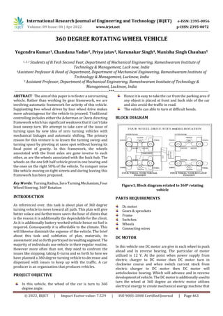
![International Research Journal of Engineering and Technology (IRJET) e-ISSN: 2395-0056
Volume: 09 Issue: 04 | Apr 2022 www.irjet.net p-ISSN: 2395-0072
© 2022, IRJET | Impact Factor value: 7.529 | ISO 9001:2008 Certified Journal | Page 464
changes over DC electrical power into mechanical power is
known as an Immediate Flow engine. DC motor working
depends on the rule that when a current conveying guide is
put in an attractive field, the guide encounters a mechanical
power. The course of this power is given by Fleming's left-
hand rule and greatness is given by;
F = BIL Newton
As per Flemings left-hand rule when an electric flow goes
through a curl in an attractive field, the attractive force
creates a force which turns the DC motor. The course of this
power is opposite to both the wire and the attractive field.
Figure no.2
GEARS DRIVE & SPROCKETS
A gears drive is utilized for transmission of mechanical
power between two sprockets. Gear drive is an approach to
communicating mechanical power starting with one spot
then onto the next. It is regularly used to pass power on to
the wheels of a vehicle, especially bikes and cruisers. It is
likewise utilized in a wide assortment of machines other
than vehicles. Most regularly, the power is conveyed by a
gear, known as the drive gear or transmission gear, ignoring
a sprocket gear, with the teeth of the stuff coinciding with
the openings in the connections of the gear. The stuff is
turned, and this pulls thegearplacingmechanical powerinto
the framework. This has transformed teeth. Here and there
the power is yield by just pivoting the gear, which can be
utilized to lift or drag objects. In different circumstances, a
subsequent stuff is put and the power is recuperated by
appending shafts or centers to this stuff. Howeverdrive gear
are regularly straightforward oval circles, they can likewise
circumvent corners by setting multiple cog wheels alongthe
gear; equips that don't put power into the framework or
send it out are for the most part known as idler-wheels. By
differing the distance across of the information furthermore,
yield gears regarding one another, the stuff proportion can
be modified. For instance, when the bike pedals gear pivot
once, it makes the stuff that drives the wheels turn more
than one transformation. A sprocket is a profiled wheel with
teeth, gear-teeth, or even sprockets that cross section witha
chain. The sprockets are utilized for the power transmission
among directing and wheel through the roller chain drive. A
sprocket[1] or sprocket wheel [2] is a profiled wheel with
teeth, or cogs,[3][4] that lattice with a chain, track or other
punctured or indented material.[5][6] The name “sprocket”
applies by and large to any wheel whereupon spiral
projections draw in a chain disregarding it. It is recognized
from stuff in that sprockets are never fit together
straightforwardly, and contrasts from a pulley in that
sprockets have teeth and pulleys are smooth.
Figure.3
FRAME
The fixed frame forms the base of the 360 degree wheel
rotation vehicle. This frame is made of Mild Steel (MS).All
parts are attached with the frame.
Figure.4
WIRES
A wire is a single, usually cylindrical, flexible strandorrod of
metal. Wires are used to bear. Wire is commonly formed by
drawing the metal through a hole in a dieordrawplate.Wire
gauges come in various standardsizes,as expressedinterms
of a gauge number. The term wire is also used more loosely
to refer to a bundle of such strands, as in "multistranded
wire", which is more correctly termed a wire rope in
mechanics, or a cable in electricity. Wire comes in solid core,
stranded, or braided forms. Although usually circular in](https://image.slidesharecdn.com/irjet-v9i483-220923104022-b99669fd/85/360-DEGREE-ROTATING-WHEEL-VEHICLE-2-320.jpg)
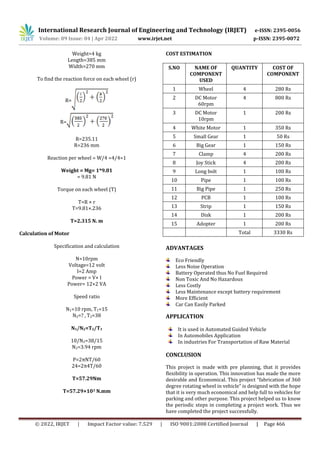
![International Research Journal of Engineering and Technology (IRJET) e-ISSN: 2395-0056
Volume: 09 Issue: 04 | Apr 2022 www.irjet.net p-ISSN: 2395-0072
© 2022, IRJET | Impact Factor value: 7.529 | ISO 9001:2008 Certified Journal | Page 465
cross-section, wire can be made in square, hexagonal,
flattened rectangular or other cross-sections, either for
decorative purposes, or for technical purposes such as high-
efficiency voice coils in loudspeakers. Edge-wound [1] coil
springs, such as the Slinky toy, are made of special flattened
wire.
Figure. 5
WHEELS
The wheel bearing help the wheels in turning without a
hitch. Fundamentally, the capacity of the wheel center point
is to keep the wheel turning unreservedly on the bearing
while at the same time keeping it appended to the vehicle.
Rolling is a productive method for lessening contact. At the
point when you slide a square acrossa smoothsurface,it will
slide for a brief distance and afterward halt. At the point
when you roll a ball across that surface, it will move far.
There are two fundamental pieces of wheels; the haggle the
hub. The actual wheel is a round plate. The hub is a shaft
situated in the focal point of the circle. Here and there the
plate itself turns on the pivot. Regularly the hub is fixed to
the circle and the haggle turn together. Whenever a wheel is
moving along the ground, a small portion of the surface
contacts the ground. However this surface doesn't need to
slide on the ground. Contact chiefly happens in the pivotand
is extraordinarily decreased. Moving erosion is a lot more
fragile than sliding erosion. By rolling, wheels make it
simpler to move things from one spot to another.
Figure.6
WORKING PRINCIPLE
In this project battery gives the power supply to the control
unit. The gear contains absolutely six engines, two engines
are combined with the vehicle's left and right wheels of the
front side, the following two engines are associated with the
vehicle's left and right half of the rear. The four engines are
utilized to run the vehicle. Another two engines are
associated with turn the vehicle wheel 360 degree by the
chain drive plans. The keypad in the control unit hassixkeys
they are left, right, forward, switch, park left, and park right.
We press the left key in the keypad the vehicle turns leftside
in an expected point, we press the right key in the keypad
the vehicle turns at right side in a required point, also the
forward and switch movementofthevehicleareconstrained
by the forward and turn around key in the keypad. We need
to leave the vehicle in left side by press the recreation area
left key then the engine associated in the chain drive is turns
the wheel left side 360 degree consequently,thenthe vehicle
is left in the left side, this process is same as right side.
Utilizing this we can undoubtedly leave the vehicle in
different regions.
COMPONENT NAME AND DIMENSION
S.NO COMPONENT
NAME
PART
OF
PIECE
DIMENSION
1 Frame Pipe 4 L=385mm ,
W=270mm
2 Motor 4 60 rpm
3 Big Motor 1 10rpm
4 Pipe 1 210 mm
5 Gear 2 D=50mm
6 Wheel 4 D=65mm
7 Disk 1 D=155mm
8 White Motor 1 Volt=24V,
Current=0.45Amp
9 Strip 1 L=490mm
10 Joy stick 4 L=344mm
11 Long bolt 1 L=170mm
12 Screw 4 Pitch=0.2mm
12 Weight 4kg
If load apply on the vehicle is 4 kg and length 385mm width
of vehicle 270 mm.
Find the reaction developed by each wheel and find the
torque of each Wheel.](https://image.slidesharecdn.com/irjet-v9i483-220923104022-b99669fd/85/360-DEGREE-ROTATING-WHEEL-VEHICLE-3-320.jpg)

This document describes a proposed 360 degree rotating wheel vehicle. The vehicle aims to reduce turning radius and space by allowing the vehicle to turn in place without leaving its center of gravity. It uses four independently rotating wheels that can turn 360 degrees, connected to DC motors. This zero turning mechanism allows the vehicle to easily maneuver in tight spaces like parking areas. The document outlines the design of the vehicle, including its frame, motors, gears, wiring and controls. It also provides calculations for wheel torque and reactions, cost estimates, advantages like being eco-friendly and battery powered, and potential future developments like using a single motor instead of separate motors. The vehicle aims to improve maneuverability and parking ability compared to traditional steering designs.