Download to read offline
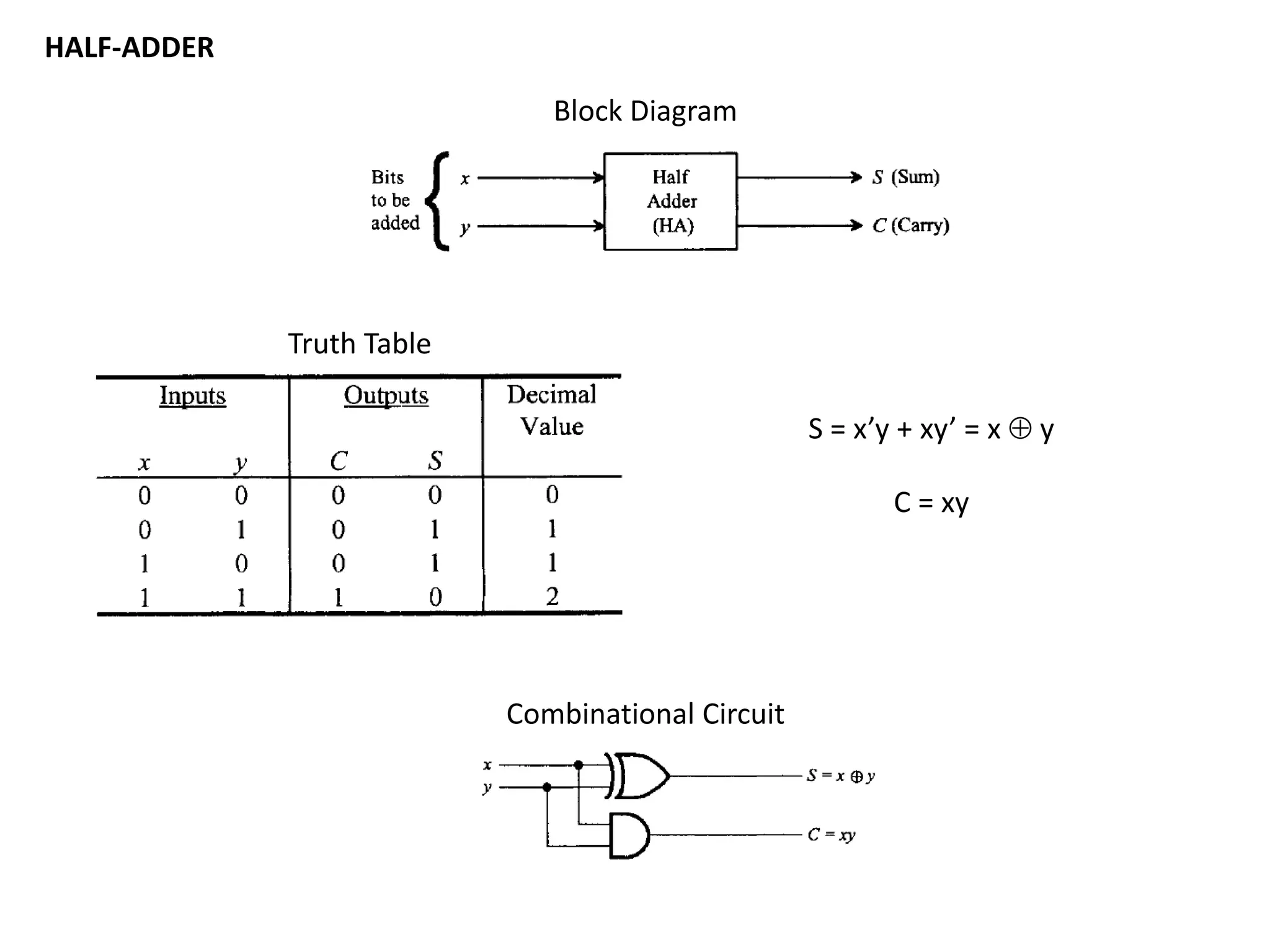
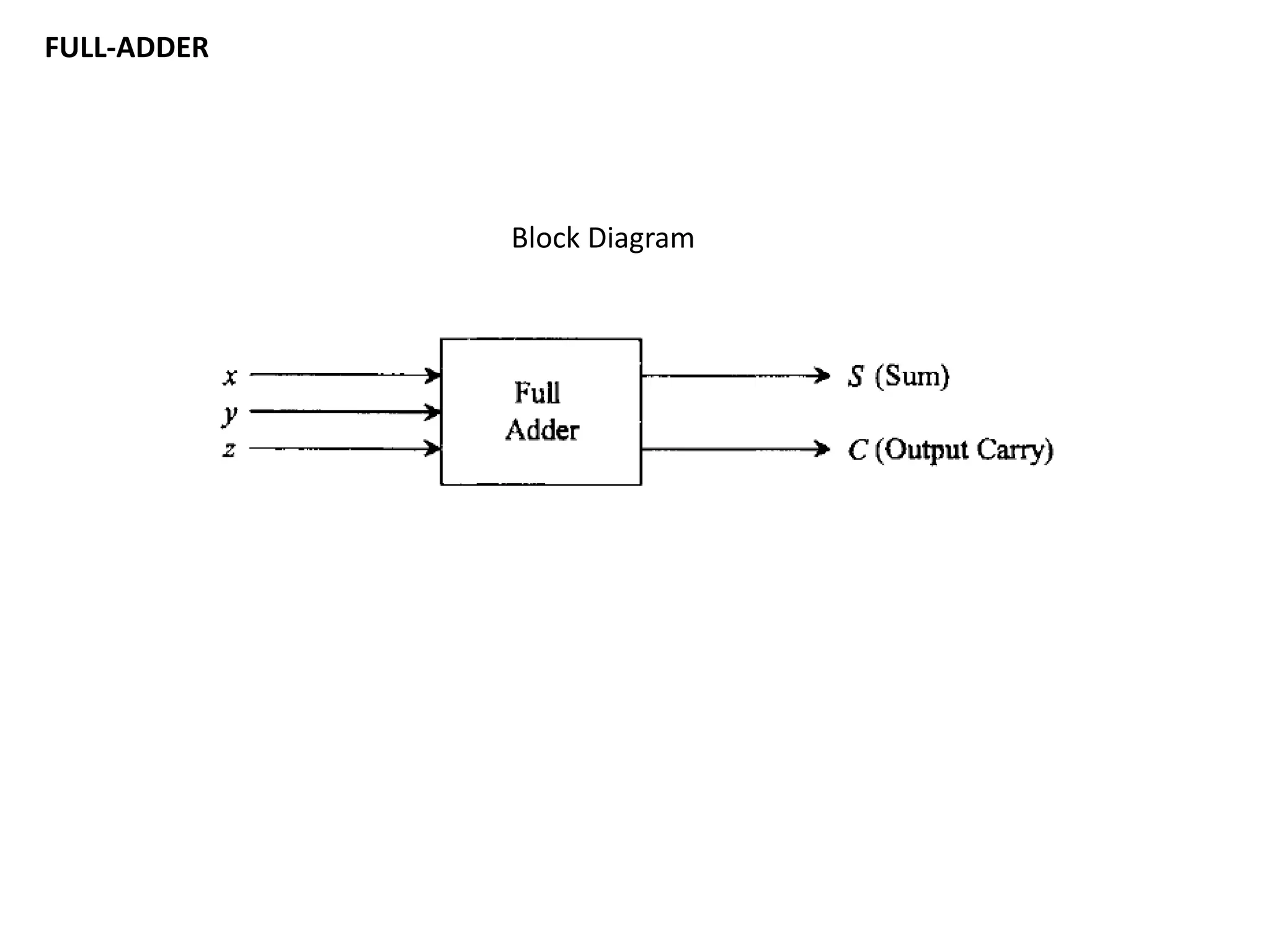
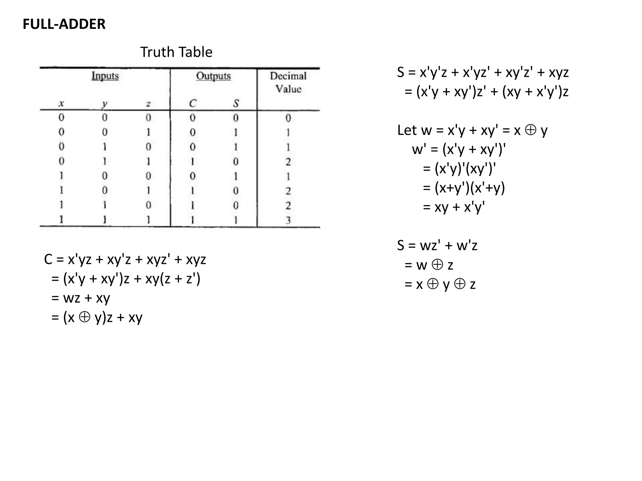
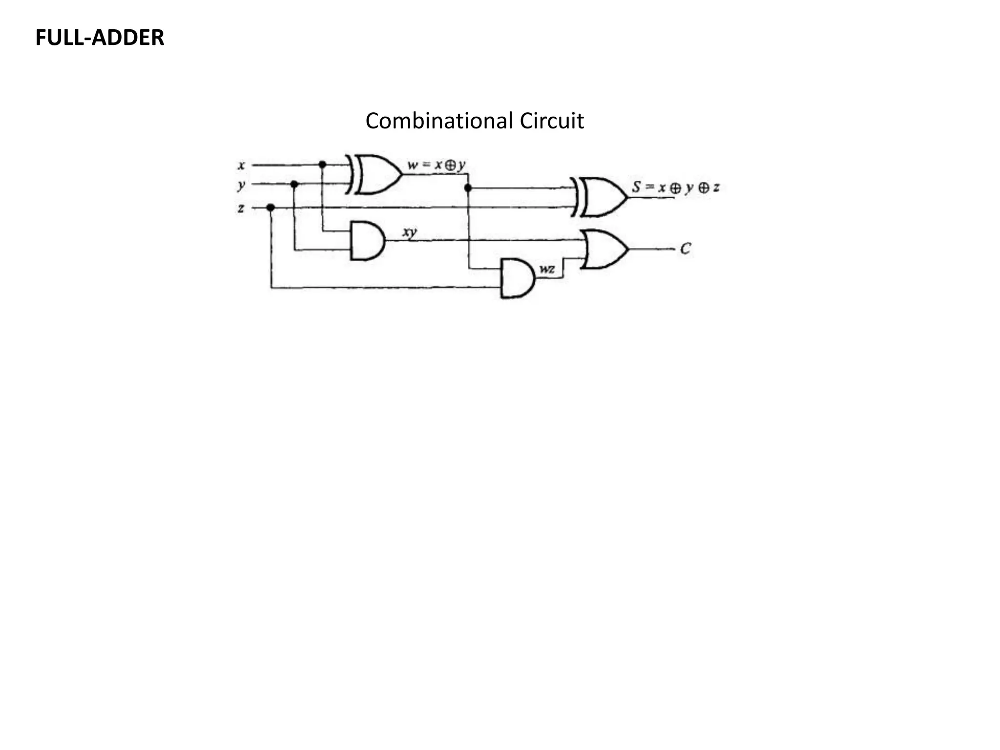
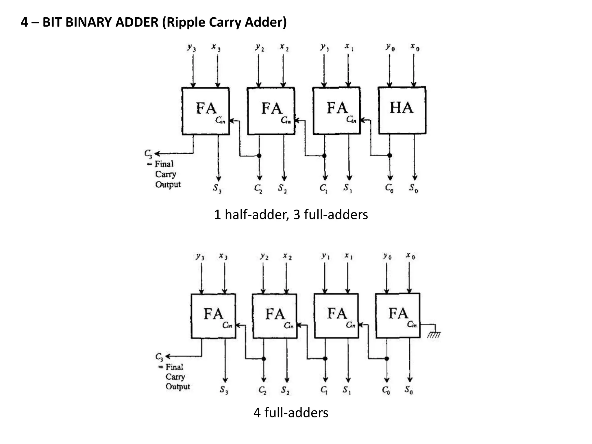
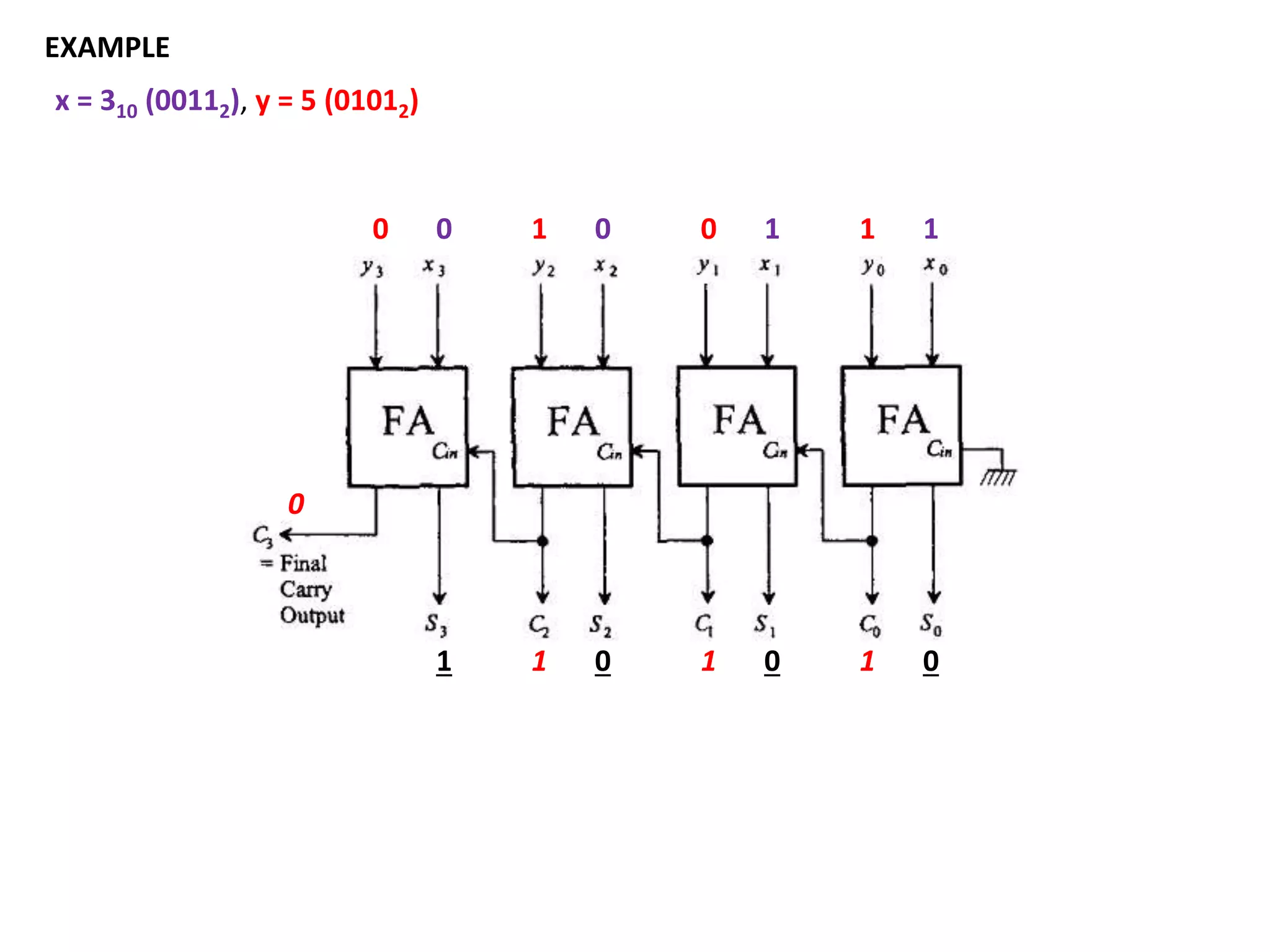
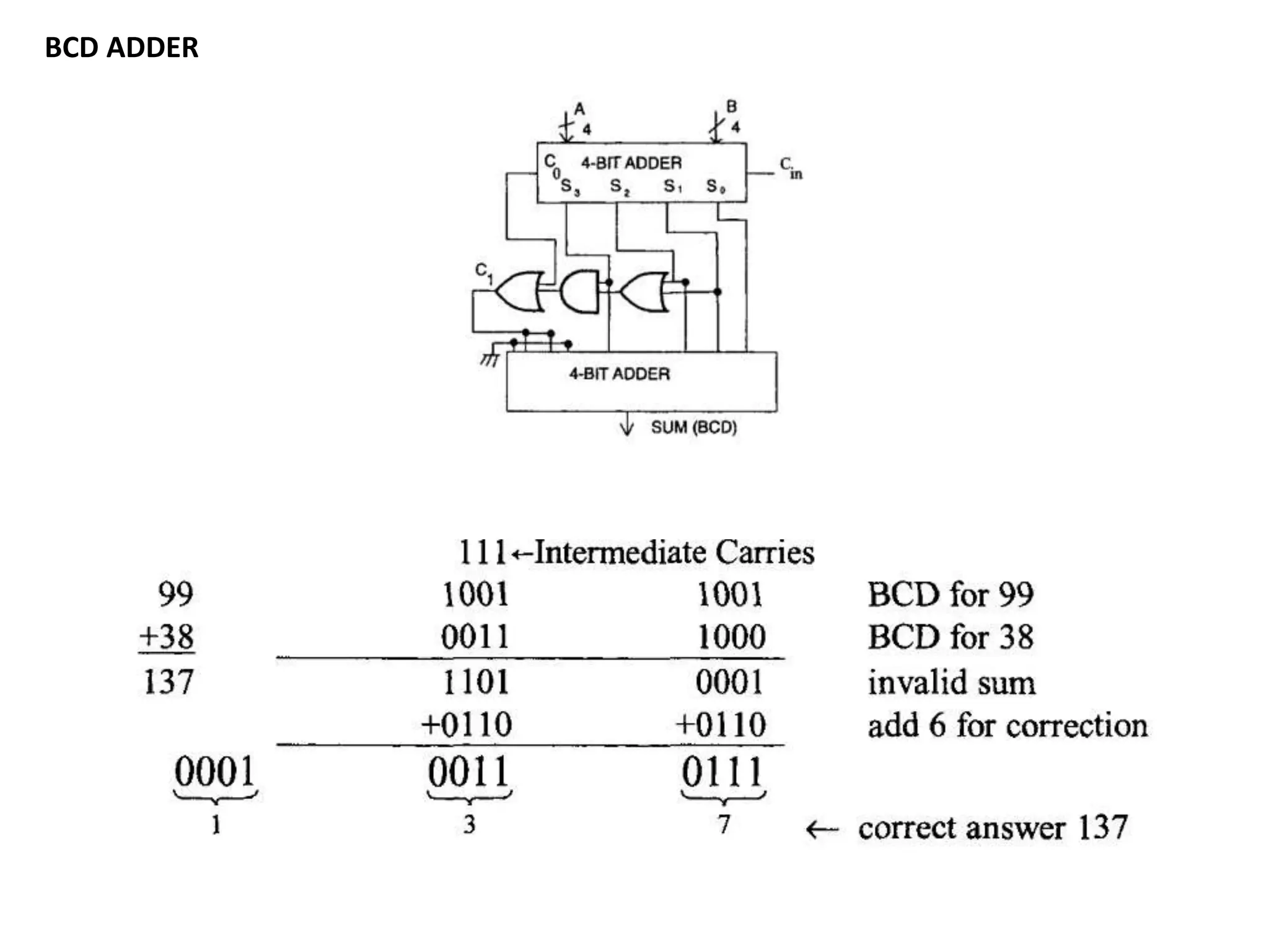
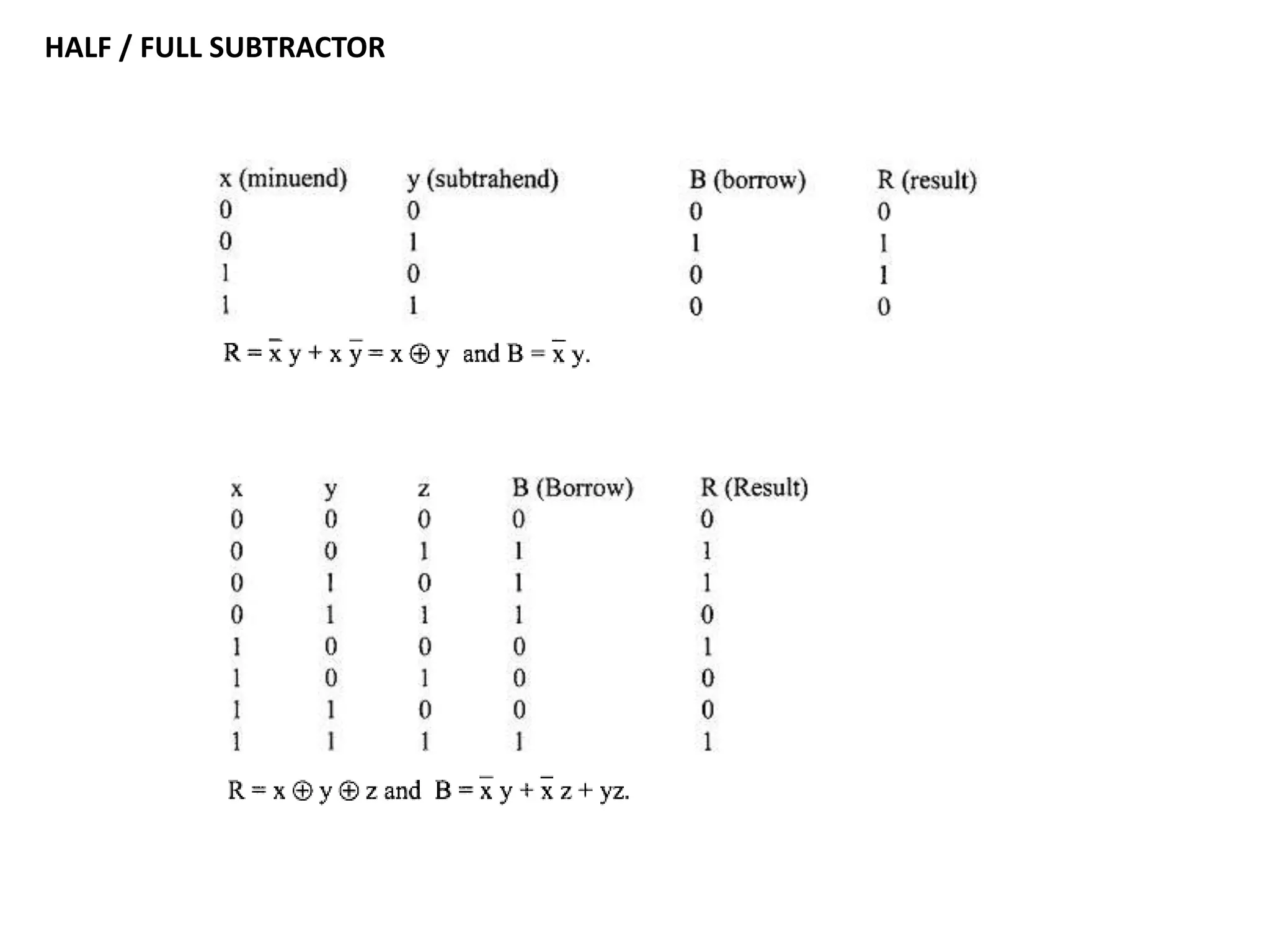
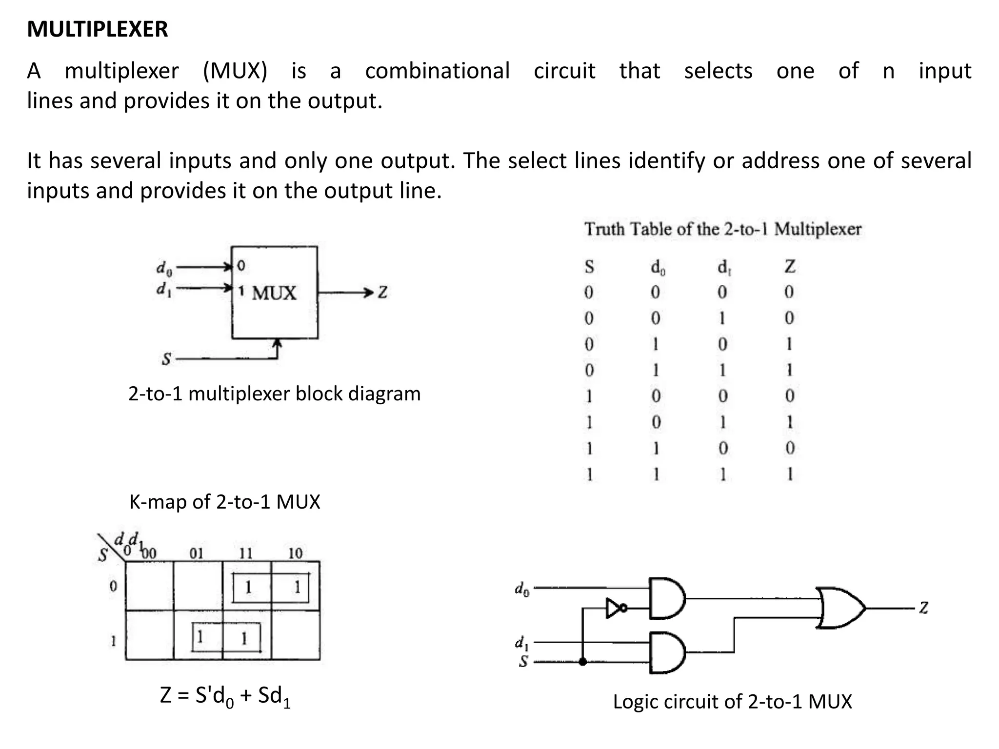
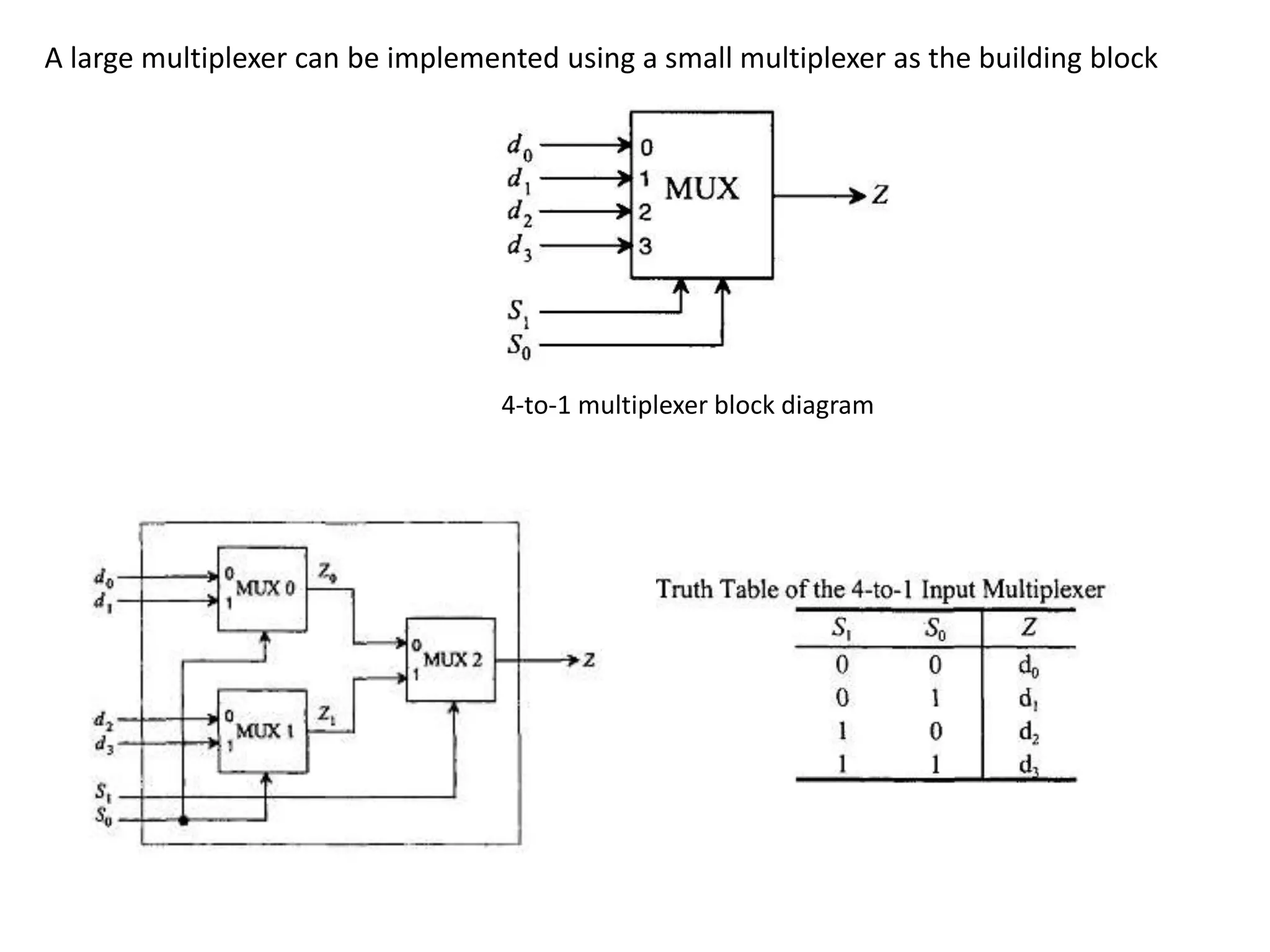
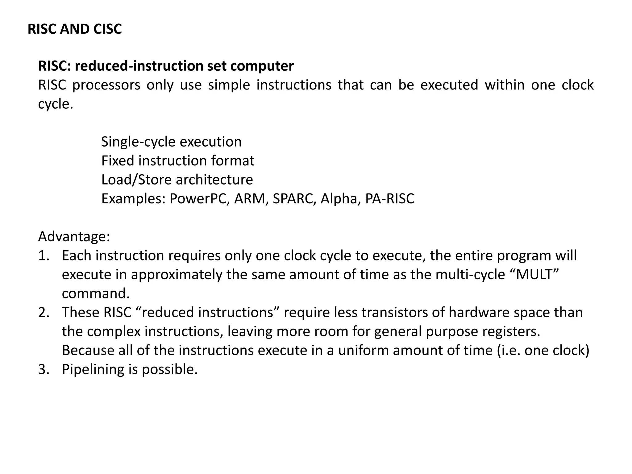
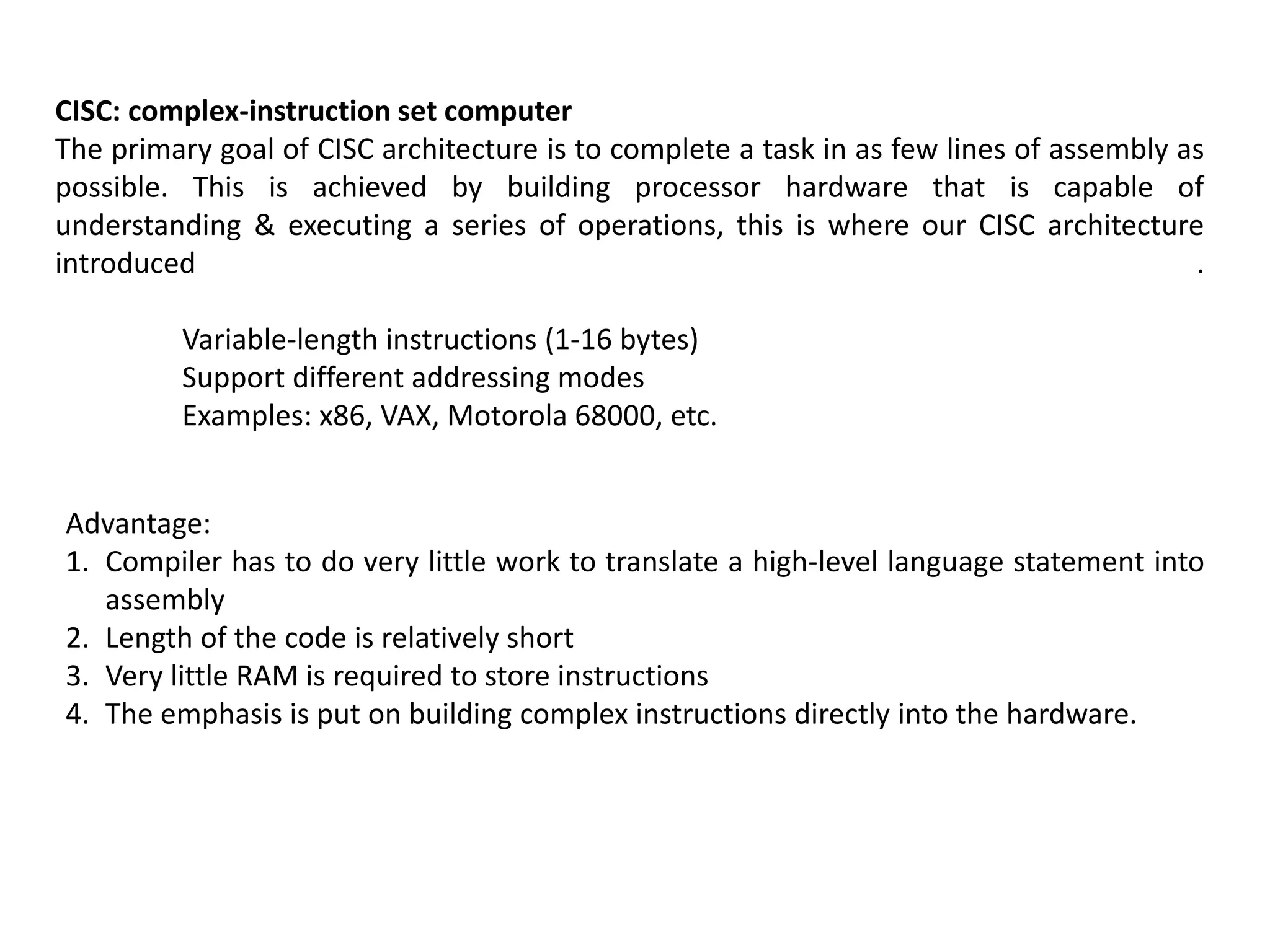
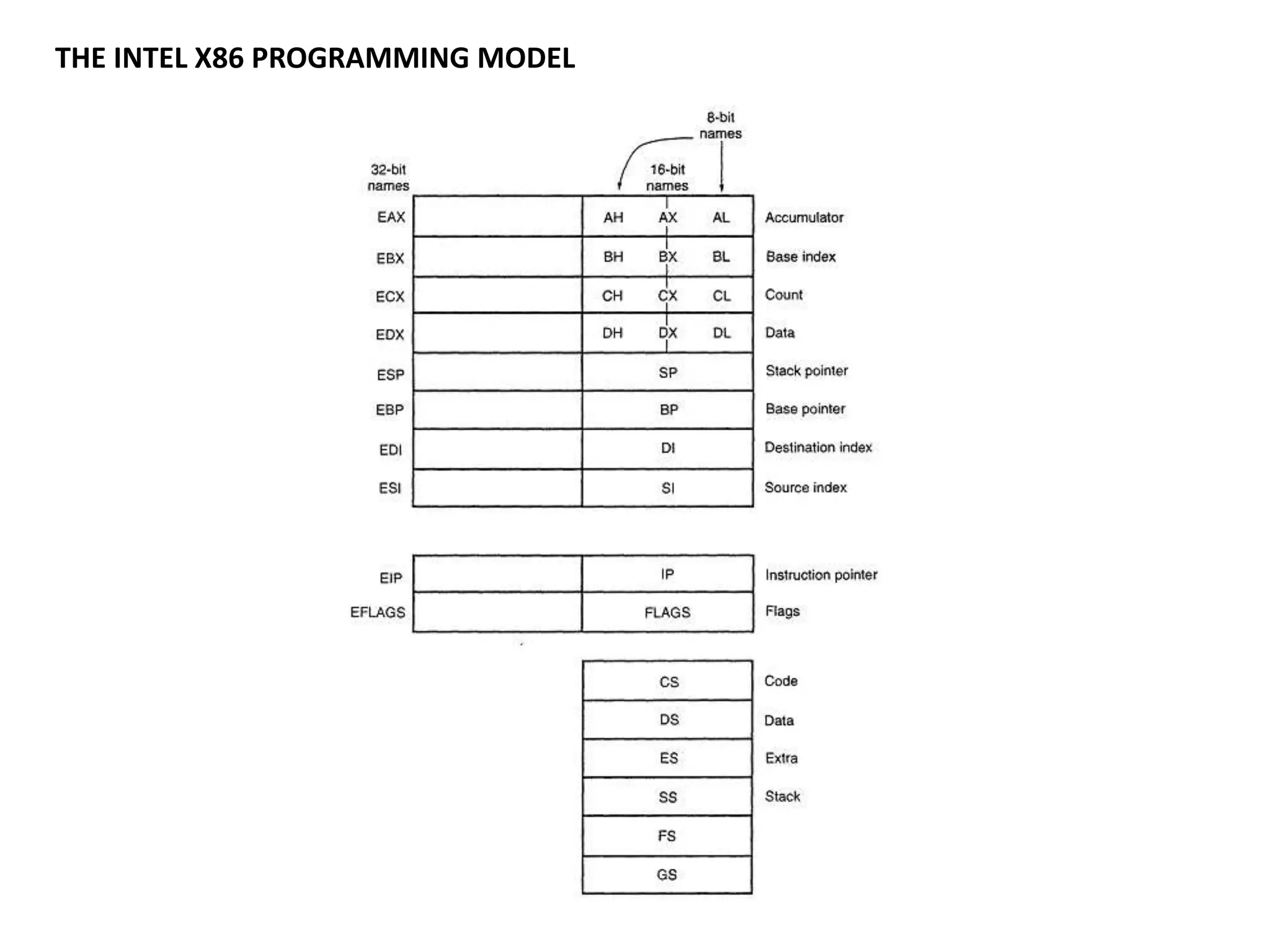

This document discusses binary and BCD adders and subtractors, including half-adders, full-adders, 4-bit binary adders, BCD adders, half/full subtractors, and multiplexers. It also discusses instruction set architecture (ISA), comparing RISC and CISC architectures, and the Intel x86 programming model.