Download to read offline


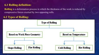
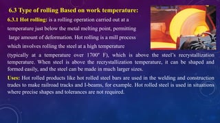
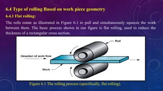
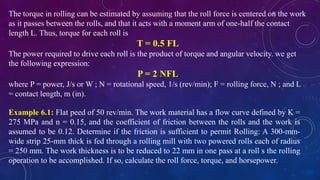
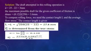
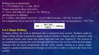
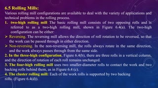
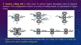
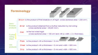

The document provides an overview of the rolling process, defining it as a deformation method that reduces the thickness of materials using two opposing rolls. It includes the types of rolling based on temperature (hot and cold rolling), their uses, specifics of flat and shape rolling, as well as various rolling mill configurations (two-high, three-high, four-high, cluster, and tandem). Additionally, it discusses the mechanics behind rolling operations including draft, torque, and power requirements.