The document discusses the Windows driver model and I/O architecture. It describes how I/O requests from applications are abstracted via IRPs that are passed to drivers. Drivers implement standard routines to handle IRPs for operations like read, write, power management. PnP manages device enumeration and loading of drivers to handle new devices. Power management coordinates transitioning devices and the system between various D-states and S-states.


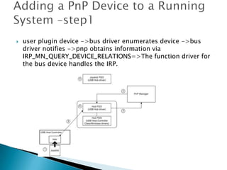
![ devnode is made up of at least two, and sometimes more,
device objects[PDO and FDO]
A physical device object (PDO) that the PnP manager instructs
a bus driver to create when the bus driver reports the
presence of a device on its bus during enumeration A
functional device object (FDO) that is created by the driver,
which is called a function driver, that the PnP manager loads
to manage a detected device.](https://image.slidesharecdn.com/windowio-130725042949-phpapp02/85/Window-IO-14-320.jpg)


![Revo Uninstaller Pro 5.2.6 Crack + License Key 2025 [Full Latest]](https://cdn.slidesharecdn.com/ss_thumbnails/windowsntinternals-chapter5-250311141151-a04115dd-250311182343-70671553-250325161717-8b824cb4-thumbnail.jpg?width=640&height=640&fit=bounds)


