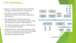
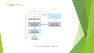
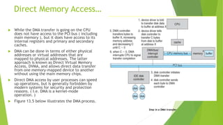
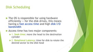
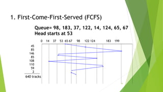
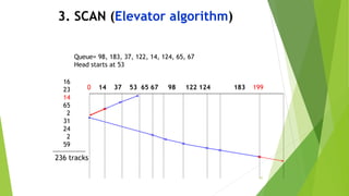
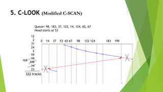
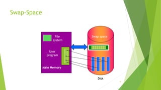
This document provides information about I/O hardware, secondary storage structures, and the system design process. It discusses different types of I/O devices and how they connect to computers via ports and buses. It describes memory-mapped I/O and how devices communicate with the CPU via registers or direct memory access. The document outlines different disk scheduling algorithms like first-come, first-served, shortest seek time first, SCAN and C-SCAN and compares their performance characteristics. It also covers interrupts and how they allow devices to notify the CPU to efficiently handle I/O transfers.


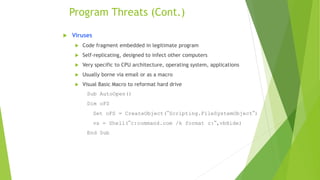


![Sobig.F Worm
More modern example
Disguised as a photo uploaded to adult newsgroup via account
created with stolen credit card
Targeted Windows systems
Had own SMTP engine to mail itself as attachment to everyone in
infect system’s address book
Disguised with innocuous subject lines, looking like it came from
someone known
Attachment was executable program that created
WINPPR23.EXE in default Windows system directory
Plus the Windows Registry
[HKCUSOFTWAREMicrosoftWindowsCurrentVersionRun]
"TrayX" = %windir%winppr32.exe /sinc
[HKLMSOFTWAREMicrosoftWindowsCurrentVersionRun]
"TrayX" = %windir%winppr32.exe /sinc](https://image.slidesharecdn.com/unit5-understandingthesystemdesignprocess-240305010723-37acd1c4/85/UNIT-5-UNDERSTANDING-THE-SYSTEM-DESIGN-PROCESS-pptx-75-320.jpg)