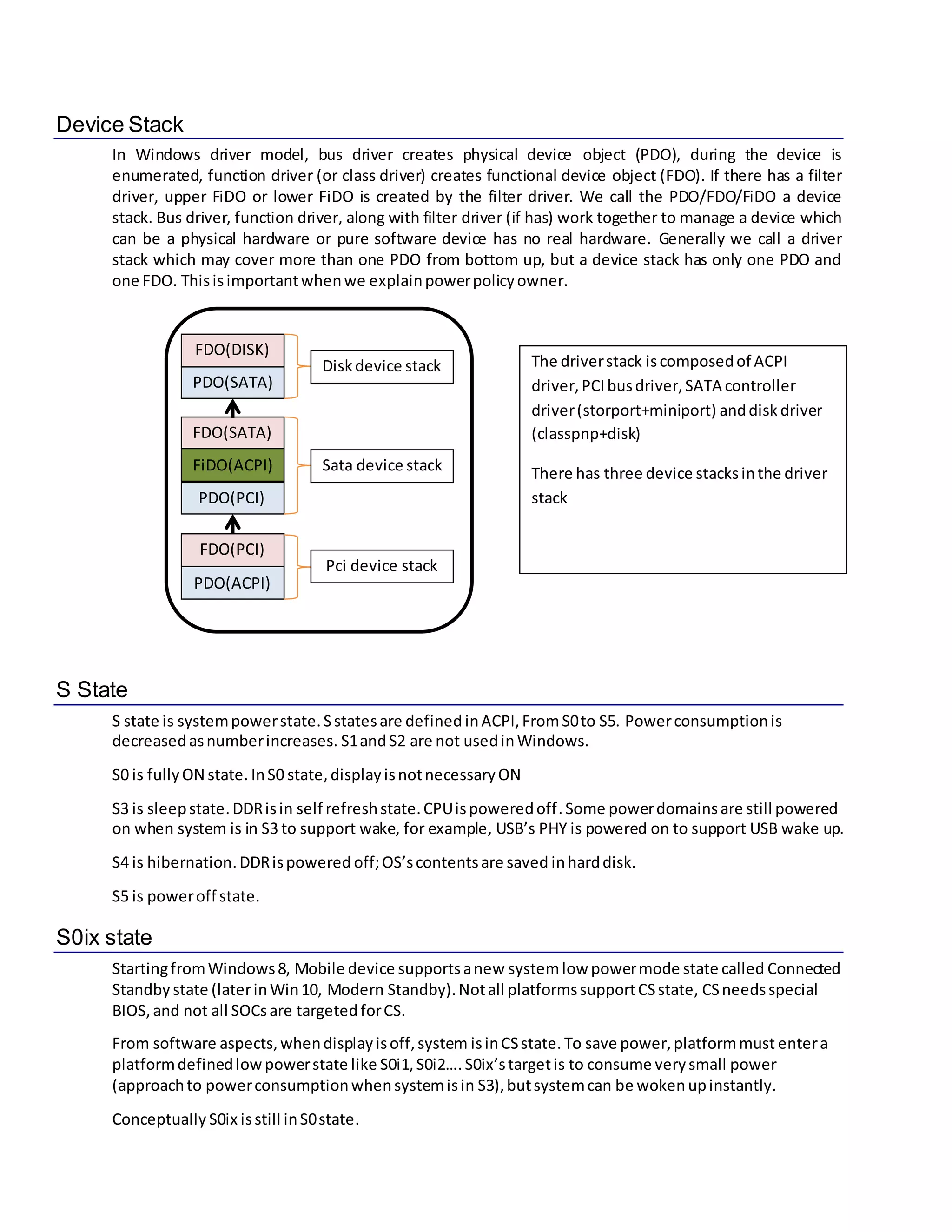
Windowspower management basic knowledge
July 28, 2015 Dave Feng
Contents
Contents................................................................................................................1
Introduction...........................................................................................................1
Power Domain (Power Rail).....................................................................................2
Dynamic clock gating..............................................................................................2
Device Stack...........................................................................................................3
S State ...................................................................................................................3
S0ix state ...............................................................................................................3
D state...................................................................................................................4
D0 and D0 initialized...............................................................................................4
D3cold to D0 process..............................................................................................4
Why D state is necessary?.......................................................................................4
Components in a device..........................................................................................5
F state....................................................................................................................5
S state to D state map.............................................................................................5
CPU C/P state.........................................................................................................5
Power manager......................................................................................................5
S IRP ......................................................................................................................5
D IRP......................................................................................................................6
D IRP Handling........................................................................................................6
Power related ACPI methods...................................................................................6
Runtime power management..................................................................................6
Runtime idle detection mechanism..........................................................................6
Power framework...................................................................................................6
System power policy owner....................................................................................7
Device power policy owner.....................................................................................7
Wake.....................................................................................................................7
Wait/Wake IRP.......................................................................................................7
Power state machine..............................................................................................7
DEVICE CAPABILITY.................................................................................................7
Power Engine Plug-in (PEP) .....................................................................................7
Introduction
Windows OS support many features in power management aspects to save power consumption and
extend mobile devices’ battery life. Software power management is a big topic, many concepts are
introduced. In a Windows driver, the power management related routines (functions) are distributed in
many places. Some of the routines in a driver are used to control hardware registers, some co-work with
OS to let the whole system work properly when state transitions, other routines may provide
informationtoothersoftware components(otherdriversorOS) tomake some policydecision.
To make the driver work properly, it is essential to understand the fundamentals in Windows power
management. Without the basic knowledge, it is difficult for a driver developer to figure out a workable
logic to enable hardware low power feature, also it is hard to communicate with HW engineers when
debuggingissues.
Power Domain (Power Rail)
SOC’scontrollersneedpowersupply(Vcc) towork. The differentpowersupplyis differentpower
domain. To save power,we need topowerdownthe whole controller’spowersupplywhenthe
controllerisnotused.Itis bettertosegregate all controllers withseparate powerrailstomaximallysave
powerconsumption, andthen everycontrollerhas individual powerdomain whichcanbe powered
on/off whenitisnotused.But powerrail take bigplace, thismeans more powerrailstake more area in
silicon,so SOCsharesone powerrail amongseveral small controllers tosave siliconarea.
Consequently,whenseveral controllersshare one powerdomain,the powersupplycannotbe shut
downevenwhenonlyone controllerisusing power. Only afterall controllersinthe powerdomainare
not used,the powerdomaincanbe shut down.The powerleakage due tothe powersupplyis called
staticpowerleakage.
1. An imaginary powerdomain has twocontrollers
2. Power domainactually is controlledby a switch
3. only SD and USB2 botharenotused, the power switchcan beoff
4. a power domain has onevoltage
A controller’ssubcomponents maybelongtodifferentpowerdomains. Everycontrollerconsistsof
manydigital..e.g. aUSB hostcontrollerhasUSB core logicandPHY. USB core logic’svoltage isdifferent
fromPHY’s voltage supply, soaUSB hostcontrollerbelongtwodifferentpower domains.
Generallycontrollerdrivercannotcontrol powerdomainbecause one controllerdriverdoesnotknowif
othercontrollersinthe same powerdomainare workingornot. Powerdomainiscontrolledbysystem
level softwarelikesystem BIOSorspecial driverlike PEPwhichknowsall drivers’powerstate.
Dynamic clock gating
A workingcontrollerinSOCorexternal deviceisdrivenbyclock. Clock’sflip-flopcanconsume much
power(dynamicpowerleakage).Whenacontrolleris idling(notused),software canshutdownthe
clock,thisis calleddynamicclockgating. Afterclockisgated, there mayhave staticpowerleakage due
to powersupply
USB2SD
Device Stack
In Windows driver model, bus driver creates physical device object (PDO), during the device is
enumerated, function driver (or class driver) creates functional device object (FDO). If there has a filter
driver, upper FiDO or lower FiDO is created by the filter driver. We call the PDO/FDO/FiDO a device
stack. Bus driver, function driver, along with filter driver (if has) work together to manage a device which
can be a physical hardware or pure software device has no real hardware. Generally we call a driver
stack which may cover more than one PDO from bottom up, but a device stack has only one PDO and
one FDO. Thisisimportantwhenwe explainpowerpolicyowner.
S State
S state is systempowerstate.Sstatesare defined inACPI, FromS0to S5. Powerconsumptionis
decreasedasnumberincreases. S1andS2 are not usedinWindows.
S0 is fullyON state. InS0 state,displayisnotnecessaryON
S3 is sleepstate.DDRisin self refreshstate.CPUispoweredoff. Some powerdomainsare still powered
on when system is in S3 to support wake, for example, USB’s PHY is powered on to support USB wake up.
S4 is hibernation.DDRispowered off;OS’scontentsare saved inharddisk.
S5 is poweroff state.
S0ix state
StartingfromWindows8, Mobile device supportsanew systemlow powermode state called Connected
Standby state (laterinWin10, Modern Standby).Notall platformssupportCSstate, CSneedsspecial
BIOS,and not all SOCsare targetedforCS.
From software aspects,whendisplayisoff,system isinCSstate. To save power,platformmust entera
platformdefinedlowpowerstate like S0i1,S0i2….S0ix’stargetis to consume verysmall power
(approachto powerconsumptionwhensystemisin S3),butsystemcan be wokenupinstantly.
Conceptually S0ix isstill inS0state.
FDO(SATA)
FiDO(ACPI)
PDO(SATA)
FDO(DISK)
FDO(PCI)
PDO(ACPI)
PDO(PCI)
Sata device stack
Pci device stack
Diskdevice stack The driverstack iscomposedof ACPI
driver,PCIbusdriver,SATA controller
driver(storport+miniport) anddisk driver
(classpnp+disk)
There has three device stacksinthe driver
stack
D state
D state isdevice’spowerstate. FromD0 to D3cold, D statesare alsodefinedinACPI.
D0 state isfullyonstate.Whena device isinD0, itis well configuredandcantransferdata. Generally,
biggerx(Dx) meanslowerpowerconsumption.
D state isa logical powerstate;ACPIdoesnotdefine how adevice should be configuredinaspecificDx
state.
For PCIdevice,PMCSRisusedto control the device’sDstate. Whena PCI device isputintoD3, PMCSR
shouldbe setD3.
For a pure software device, suchasthe device whichisdrivenbyaprotocol driver,the D state is
meaninglessfrompowerconsumption perspective,butDstate is usedtodescribe the logical power
state to communicate withOSor otherdrivers.
For otherreal hardware devices,itisthe driverorplatform’sresponsibility tomapthe D state to a
hardware state and define howtoconfigure the hardware whenthe device powerstate transitions. For
example, whenharddiskisinD3 state,diskdriverdecidesonhow toconfigure the harddiskto save
power. Maybe stoprotating,poweroff some powersupply.
Notall drivers change hardware configuration whenthe device’sDstate transitions. Some drivermay
change hardware’spowersettings whenthe device isidle tosave powerevenwhenthe device is inD0
state.Keepthisinmind.
D0 and D0 initialized
There has anotherstate calledD0 uninitialized.Frompowersupplyperspective,D0is the same as D0
uninitialized. The difference betweenD0and D0 uninitializedis:onlyaftersoftwareproperlyconfiguring
a D0 uninitializeddevice,thenthisdevicetransitionstoD0. A device inD0 un-initializedstate cannotbe
usedto transferdata. For example,aUSB controllerisinD0 un-initialized state cannotenumerate
device andthe USB core cannot work,only afteritsregistersare configured(asUSBcontrollerdefines),
the controllercanwork properly.
D3cold to D0 process
Whena controllerisinD3cold state, generally itspowersupplyistotallyoff. Buttosupportwake up,a
controllerinD3 coldmay alsohave some side bandsignals,soitmay have verysmall powersupplyto
maintainitsstate.
Whena controllerisinD3 cold,all the controllersshare the same power domainwithitare alsoinD3
cold.To transitionthe controllertoD0, the powerdomainshouldpoweron,thenall the controllers are
inD0 un-initializedstate,thendrivercanconfigure the controllertotransitiontoD0.
Why D state is necessary?
As explainedabove,Dstate isa logical state;some devices’ real hardware powerconsumption mayhave
no difference betweenwhentheyare inD0and in D3. Why itis necessarytouse D states?
UsingD statesisto communicate betweensoftware components.
1. OS cannotknoweverydevice’spowerstate withoutavariable totrack.
2. A buscan entera lowerpowermode only if all itschildrenare ina lowerpowerstate. Withouta
device powerstate variable, busdriverdoesnotitschildren’spowerstate.
3. Systemcan enterS3 onlyafterthe whole system’sdevicesare inlowerpowerstate. Withouta
device powerstate variable,systemdoesnotknow whenitcanentersleepstate
Components in a device
Some complex devices mayhave several inter-dependentcomponents, anaudiodevicecanhave
playbackandrecorderfunctions. Tosave power;powermanagercan manage the components
separately.Mostreal hardware deviceshave onlyone component.
F state
F state is component’spowerstate.DefiningFstate isto control differentpower consumption levels
whena device isinD0. Whena device isinD0, componentsinthisdevice canhave F0,F1, F2,…Fn states.
The deeperFstate is,the lesspowerisconsumed. A componentcanenterFn powerstate (n!=0) from
F0, and fromFn to F0, but cannotentera lowerpowerF state fromanotherlowerpowerFstate. That is
to say, a component cannot enter F2 from F1. When a componentis in F1, and can enter F2 after a while,
powermanagerwill putthe componentintoF0firstly, andthen putit to F2 state.
S state to D state map
Calculatingthe accurate D state whensystemisinSx isreallycomplex,itneedsACPIdriver,parent
driverandBIOS co-operation.By default,whensystemisinS3 or S4, all devicesare inD3. If a device can
supportwakeup,butthe wakeupsignal canonlybe generatedinD0 or D1 or D2, in suchcase,when
systemisinS3, device maybe notinD3.
CPU C/P state
CPU core (cache,PLL, clock…) consumesmuchpowerwhenitisrunningcode,butfor a computer,most
time CPU isidle. Cx(x!=0) isCPU core powerstate whenitisidle. The largerx,the deeperstate the core
is,and the more time isneededtocome back to C0. For X86 architecture, core entersC1by executing
_HLT instruction,entersC2byexecutingI/Oreadinstruction,the I/Oportaddress isdesignatedin BIOS.
Generally,deeperstate thanC2 is implementedin hardware;enteringintothesestatesisautomatically
done byhardware.
EvenwhenCPU isin C0 state,it can run at differentfrequencylevels,higherfrequencylevel consumes
more power.To dynamicallychange the frequency,Pstate isused. OSpowermanagercan select
differentPsate basedonthe workingload.
Power manager
Powermanagerisan OS kernel module (inntoskrnl.exe).Powermangerisresponsible forall kindsof
powermanagementrelatedjobs.CPUpowerstate decisionmaking, managespowersettings,collects
userinput,tracks all devices’Dstate, components’F state tracking.
S IRP
Before systemstate transitions,powermanagerinitiatesanIRPanddirectsto device driver. ThisIRP
tellsdriverthatsystemistryingtochange S state,and drivershould handle thisIRP.Onlypower
managercan create andinitiates SIRP.
D IRP
D IRP isrelatedtodevice powerstate. DIRP isinitiatedbypowermanageror device driver. Whenpower
mangerwantsto transitiona device’spowerstate,itcaninitiate aD IRP andsendsto the device driver.
Whena device receives anS IRP,to handle the SIRP, the device drivermayneedtochange the device’s
D powerstate,insuch case,device drivercaninitiate aD IRP.
D IRP Handling
Whendevice driverreceives DpowerIRP,generallyitpassesdownbecausebusdriverwilldothe real
jobto put the real hardware intolowerpowerstate
If a drivercan control the hardware and putthe hardware intolowerpowermode,generallyitcannot
put the device intolowerdevice powerstate bysettingthe hardware registerwithoutinitiatedevice
powerIRP.Drivermustletthe powermanager know that it will transitiontoanotherdevice powerstate
by requestingpowerIRP,orthe powermanagerdoesnotknow the device’spowerstate atall.
PowerrelatedIRPhandlingisdone byWDFif the driverisWDF based
Power related ACPI methods
Whena device isputin lowerpowermode like D3,itspowerresource (like Vcc) canbe shut down,but
such powerresource generally cannotbe controlledinWindowsdriver because the powerresource is
platformdependent. BIOSisthe place tocontrol the powerresource.
In such case,a methodiscreated inBIOS for the device,whendevice’spowerstate transitions, ACPI
driverwill invokethe methodinBIOS. How doesACPIdriverknow whenthe device powerstate
transition?Because the deviceisdeclaredin ACPIname space,ACPIdriveristhe device’s filterdriver.
Runtime power management
Runtime device powermanagementmeanswhensystemisS0,Device isnotnecessaryalwaysinD0,
whendevice isnotused(idle),devicepower state cantransition toDx(x!=0) orcomponentpowerstate
can transitionto Fx(x!=0)
Runtime idle detectionmechanism
WhensystemisinS0 and device isnotused(noinprogressI/O),we call the device isinidle state.
Generally if the device isnotused,drivercanput the device inlowerpowerstate (Dx),butfrequently
transitioningthe device intoandoutof a D state needsmuchtime,so an idle timerisused. Only after
the device isbeingidle some time,driverputsthe device intoalowerpowerstate.
Power framework
Powerframework orruntime powerframework isaset of kernel APIsfordriverdevelopment.A driver
can registerwithpowerframework, andprovide some callbacks, whensystemisrunning, kernel power
managerwill call the driverprovided callbackswhenthe device isidle,orFstate transition,or D state
transition…
System power policyowner
Systempowerpolicyownerisactuallykernel powermanager. Itdecidesafterhow longthe systemis
beingidle, andthen systemcanenterS3;powerusage in AC/DCmode;CPU idle residency parameters;
core parkingparameters;whatpowerscheme isused…
Device power policy owner
Device powerpolicy owneristhe device stack’sfunction driver.Thisfunctiondriverdecides how to
define the device’sidleness,whenthe devicepowerD/Fstate canchange,and the powerstate
dependency onotherdevice’spowerstate…
Wake
Systemwake up
Whenthe systemtransitionsfromS3/S0ix toS0, we call system wake up. Generally itisdue towakeup
source (external wakeupinterruptsor timer/RTC)
Device wake up
Device wake upmeanswhensystemisinS0, but the device isinD3 (powerislost),andthe device has
the capabilitytodetectsome external signals, whenthe signal happens,the device canpoweronthe
device itselfwithdriver’sco-work.
Device wake upisdifferent fromdevice resume:Forexample,whenastorage device isinD3, the
storage drivercan transitionthe storage device fromD3to D0 afterreceivesincomingI/O,thisisdevice
resume notdevice wake up.
Wait/Wake IRP
Power state machine
Powerstate machine isa diagramOS or a device drivermaintains, thisdiagramtracksthe whole system
powerstatesor the device powerstateswhichare internallyusedbyOSor the driver.
For a device,the powerstatesare,butnotlimitedto,Dx and Fx, because powerstates’ transitionsare
verycomplex,todescribe everyspecificstate,powerstate machine generallyrecordsmany
DEVICE CAPABILITY
Device capabilityisadevice’sPNP andpowerattributes,PNPgetsadevice’scapabilityviasendingPNP
IRP to the device anddevice functiondriverpassdownthe IRP,afterIRP reachestobus driver,but
driverfillsthe datastructure baseduponreal hardware capabilityorACPI setting.When the IRPis
completing, function drivercanchange the capability’sdatamemberperreal hardware attribute orreal
usage case,finallyPNPmanagergetsthe device’scapability.Device’s capabilitycan decide if the device
can wake up the systeminSx,if it isremovable…
Power Engine Plug-in (PEP)
Why needPEP?
S/D/Fstatesresolvesmanypowermanagement problemsandimprove powerefficiencymuch,butnot
all.To resolve followingquestions,we needanew driver,
1. Some devicesshare clock,whenone of the devicesisnotused, somehow itwill be inD3if the
driverapplyruntime powermanagement,whenall the devicesare notused,the sharedclock
shouldbe shutdown to save power,butdriversshare the same clockdo not communicate, so
evenall devicesare inD3, nobody will shutdownthe clock.we needadrivertotrack all the
devices’state,whenall the devicesare inD3, thisdrivercan shutdown the clock
2. Evenwhenall of the processor’scoresare inthe lowestpowerstate andall devicesare in
D3cold,the systemstill consumespowerinsystemlevel,we canpowerdownthe whole system
(leave minimal poweronformaintainingwake uplogic).We needadrivertodefine asystem
lowpowermode (S0ix),thislowpowermode dependsoncore’sCstate and devices’Dstate.
3. Some CPU’slowpowermode dependsondevice’sactivity. Forexample,whenUSBhas DMA
transfer,CPU cannotenterC2. CPU’s low powermode entryisofferedbyOS,if OSisnot aware
of the dependency,C2entrycan lead unpredictable result. Insuchcase,we needa drivertotell
OS the CPU’s lowpowerdependencyondevice.
PEP issuch kinddriver, wheneverfollowingstate transitions,powermanagerwillnotifyPEPdriver,then
PEP drivercandecide whatto do
1. a device D state
2. a component’sFsate
3. CPU’s C state

Windows power management basic knowledge

  • 1.
    Windowspower management basicknowledge July 28, 2015 Dave Feng Contents Contents................................................................................................................1 Introduction...........................................................................................................1 Power Domain (Power Rail).....................................................................................2 Dynamic clock gating..............................................................................................2 Device Stack...........................................................................................................3 S State ...................................................................................................................3 S0ix state ...............................................................................................................3 D state...................................................................................................................4 D0 and D0 initialized...............................................................................................4 D3cold to D0 process..............................................................................................4 Why D state is necessary?.......................................................................................4 Components in a device..........................................................................................5 F state....................................................................................................................5 S state to D state map.............................................................................................5 CPU C/P state.........................................................................................................5 Power manager......................................................................................................5 S IRP ......................................................................................................................5 D IRP......................................................................................................................6 D IRP Handling........................................................................................................6 Power related ACPI methods...................................................................................6 Runtime power management..................................................................................6 Runtime idle detection mechanism..........................................................................6 Power framework...................................................................................................6 System power policy owner....................................................................................7 Device power policy owner.....................................................................................7 Wake.....................................................................................................................7 Wait/Wake IRP.......................................................................................................7 Power state machine..............................................................................................7 DEVICE CAPABILITY.................................................................................................7 Power Engine Plug-in (PEP) .....................................................................................7 Introduction Windows OS support many features in power management aspects to save power consumption and extend mobile devices’ battery life. Software power management is a big topic, many concepts are introduced. In a Windows driver, the power management related routines (functions) are distributed in many places. Some of the routines in a driver are used to control hardware registers, some co-work with OS to let the whole system work properly when state transitions, other routines may provide informationtoothersoftware components(otherdriversorOS) tomake some policydecision.
  • 2.
    To make thedriver work properly, it is essential to understand the fundamentals in Windows power management. Without the basic knowledge, it is difficult for a driver developer to figure out a workable logic to enable hardware low power feature, also it is hard to communicate with HW engineers when debuggingissues. Power Domain (Power Rail) SOC’scontrollersneedpowersupply(Vcc) towork. The differentpowersupplyis differentpower domain. To save power,we need topowerdownthe whole controller’spowersupplywhenthe controllerisnotused.Itis bettertosegregate all controllers withseparate powerrailstomaximallysave powerconsumption, andthen everycontrollerhas individual powerdomain whichcanbe powered on/off whenitisnotused.But powerrail take bigplace, thismeans more powerrailstake more area in silicon,so SOCsharesone powerrail amongseveral small controllers tosave siliconarea. Consequently,whenseveral controllersshare one powerdomain,the powersupplycannotbe shut downevenwhenonlyone controllerisusing power. Only afterall controllersinthe powerdomainare not used,the powerdomaincanbe shut down.The powerleakage due tothe powersupplyis called staticpowerleakage. 1. An imaginary powerdomain has twocontrollers 2. Power domainactually is controlledby a switch 3. only SD and USB2 botharenotused, the power switchcan beoff 4. a power domain has onevoltage A controller’ssubcomponents maybelongtodifferentpowerdomains. Everycontrollerconsistsof manydigital..e.g. aUSB hostcontrollerhasUSB core logicandPHY. USB core logic’svoltage isdifferent fromPHY’s voltage supply, soaUSB hostcontrollerbelongtwodifferentpower domains. Generallycontrollerdrivercannotcontrol powerdomainbecause one controllerdriverdoesnotknowif othercontrollersinthe same powerdomainare workingornot. Powerdomainiscontrolledbysystem level softwarelikesystem BIOSorspecial driverlike PEPwhichknowsall drivers’powerstate. Dynamic clock gating A workingcontrollerinSOCorexternal deviceisdrivenbyclock. Clock’sflip-flopcanconsume much power(dynamicpowerleakage).Whenacontrolleris idling(notused),software canshutdownthe clock,thisis calleddynamicclockgating. Afterclockisgated, there mayhave staticpowerleakage due to powersupply USB2SD
  • 3.
    Device Stack In Windowsdriver model, bus driver creates physical device object (PDO), during the device is enumerated, function driver (or class driver) creates functional device object (FDO). If there has a filter driver, upper FiDO or lower FiDO is created by the filter driver. We call the PDO/FDO/FiDO a device stack. Bus driver, function driver, along with filter driver (if has) work together to manage a device which can be a physical hardware or pure software device has no real hardware. Generally we call a driver stack which may cover more than one PDO from bottom up, but a device stack has only one PDO and one FDO. Thisisimportantwhenwe explainpowerpolicyowner. S State S state is systempowerstate.Sstatesare defined inACPI, FromS0to S5. Powerconsumptionis decreasedasnumberincreases. S1andS2 are not usedinWindows. S0 is fullyON state. InS0 state,displayisnotnecessaryON S3 is sleepstate.DDRisin self refreshstate.CPUispoweredoff. Some powerdomainsare still powered on when system is in S3 to support wake, for example, USB’s PHY is powered on to support USB wake up. S4 is hibernation.DDRispowered off;OS’scontentsare saved inharddisk. S5 is poweroff state. S0ix state StartingfromWindows8, Mobile device supportsanew systemlow powermode state called Connected Standby state (laterinWin10, Modern Standby).Notall platformssupportCSstate, CSneedsspecial BIOS,and not all SOCsare targetedforCS. From software aspects,whendisplayisoff,system isinCSstate. To save power,platformmust entera platformdefinedlowpowerstate like S0i1,S0i2….S0ix’stargetis to consume verysmall power (approachto powerconsumptionwhensystemisin S3),butsystemcan be wokenupinstantly. Conceptually S0ix isstill inS0state. FDO(SATA) FiDO(ACPI) PDO(SATA) FDO(DISK) FDO(PCI) PDO(ACPI) PDO(PCI) Sata device stack Pci device stack Diskdevice stack The driverstack iscomposedof ACPI driver,PCIbusdriver,SATA controller driver(storport+miniport) anddisk driver (classpnp+disk) There has three device stacksinthe driver stack
  • 4.
    D state D stateisdevice’spowerstate. FromD0 to D3cold, D statesare alsodefinedinACPI. D0 state isfullyonstate.Whena device isinD0, itis well configuredandcantransferdata. Generally, biggerx(Dx) meanslowerpowerconsumption. D state isa logical powerstate;ACPIdoesnotdefine how adevice should be configuredinaspecificDx state. For PCIdevice,PMCSRisusedto control the device’sDstate. Whena PCI device isputintoD3, PMCSR shouldbe setD3. For a pure software device, suchasthe device whichisdrivenbyaprotocol driver,the D state is meaninglessfrompowerconsumption perspective,butDstate is usedtodescribe the logical power state to communicate withOSor otherdrivers. For otherreal hardware devices,itisthe driverorplatform’sresponsibility tomapthe D state to a hardware state and define howtoconfigure the hardware whenthe device powerstate transitions. For example, whenharddiskisinD3 state,diskdriverdecidesonhow toconfigure the harddiskto save power. Maybe stoprotating,poweroff some powersupply. Notall drivers change hardware configuration whenthe device’sDstate transitions. Some drivermay change hardware’spowersettings whenthe device isidle tosave powerevenwhenthe device is inD0 state.Keepthisinmind. D0 and D0 initialized There has anotherstate calledD0 uninitialized.Frompowersupplyperspective,D0is the same as D0 uninitialized. The difference betweenD0and D0 uninitializedis:onlyaftersoftwareproperlyconfiguring a D0 uninitializeddevice,thenthisdevicetransitionstoD0. A device inD0 un-initializedstate cannotbe usedto transferdata. For example,aUSB controllerisinD0 un-initialized state cannotenumerate device andthe USB core cannot work,only afteritsregistersare configured(asUSBcontrollerdefines), the controllercanwork properly. D3cold to D0 process Whena controllerisinD3cold state, generally itspowersupplyistotallyoff. Buttosupportwake up,a controllerinD3 coldmay alsohave some side bandsignals,soitmay have verysmall powersupplyto maintainitsstate. Whena controllerisinD3 cold,all the controllersshare the same power domainwithitare alsoinD3 cold.To transitionthe controllertoD0, the powerdomainshouldpoweron,thenall the controllers are inD0 un-initializedstate,thendrivercanconfigure the controllertotransitiontoD0. Why D state is necessary? As explainedabove,Dstate isa logical state;some devices’ real hardware powerconsumption mayhave no difference betweenwhentheyare inD0and in D3. Why itis necessarytouse D states? UsingD statesisto communicate betweensoftware components. 1. OS cannotknoweverydevice’spowerstate withoutavariable totrack.
  • 5.
    2. A buscanentera lowerpowermode only if all itschildrenare ina lowerpowerstate. Withouta device powerstate variable, busdriverdoesnotitschildren’spowerstate. 3. Systemcan enterS3 onlyafterthe whole system’sdevicesare inlowerpowerstate. Withouta device powerstate variable,systemdoesnotknow whenitcanentersleepstate Components in a device Some complex devices mayhave several inter-dependentcomponents, anaudiodevicecanhave playbackandrecorderfunctions. Tosave power;powermanagercan manage the components separately.Mostreal hardware deviceshave onlyone component. F state F state is component’spowerstate.DefiningFstate isto control differentpower consumption levels whena device isinD0. Whena device isinD0, componentsinthisdevice canhave F0,F1, F2,…Fn states. The deeperFstate is,the lesspowerisconsumed. A componentcanenterFn powerstate (n!=0) from F0, and fromFn to F0, but cannotentera lowerpowerF state fromanotherlowerpowerFstate. That is to say, a component cannot enter F2 from F1. When a componentis in F1, and can enter F2 after a while, powermanagerwill putthe componentintoF0firstly, andthen putit to F2 state. S state to D state map Calculatingthe accurate D state whensystemisinSx isreallycomplex,itneedsACPIdriver,parent driverandBIOS co-operation.By default,whensystemisinS3 or S4, all devicesare inD3. If a device can supportwakeup,butthe wakeupsignal canonlybe generatedinD0 or D1 or D2, in suchcase,when systemisinS3, device maybe notinD3. CPU C/P state CPU core (cache,PLL, clock…) consumesmuchpowerwhenitisrunningcode,butfor a computer,most time CPU isidle. Cx(x!=0) isCPU core powerstate whenitisidle. The largerx,the deeperstate the core is,and the more time isneededtocome back to C0. For X86 architecture, core entersC1by executing _HLT instruction,entersC2byexecutingI/Oreadinstruction,the I/Oportaddress isdesignatedin BIOS. Generally,deeperstate thanC2 is implementedin hardware;enteringintothesestatesisautomatically done byhardware. EvenwhenCPU isin C0 state,it can run at differentfrequencylevels,higherfrequencylevel consumes more power.To dynamicallychange the frequency,Pstate isused. OSpowermanagercan select differentPsate basedonthe workingload. Power manager Powermanagerisan OS kernel module (inntoskrnl.exe).Powermangerisresponsible forall kindsof powermanagementrelatedjobs.CPUpowerstate decisionmaking, managespowersettings,collects userinput,tracks all devices’Dstate, components’F state tracking. S IRP Before systemstate transitions,powermanagerinitiatesanIRPanddirectsto device driver. ThisIRP tellsdriverthatsystemistryingtochange S state,and drivershould handle thisIRP.Onlypower managercan create andinitiates SIRP.
  • 6.
    D IRP D IRPisrelatedtodevice powerstate. DIRP isinitiatedbypowermanageror device driver. Whenpower mangerwantsto transitiona device’spowerstate,itcaninitiate aD IRP andsendsto the device driver. Whena device receives anS IRP,to handle the SIRP, the device drivermayneedtochange the device’s D powerstate,insuch case,device drivercaninitiate aD IRP. D IRP Handling Whendevice driverreceives DpowerIRP,generallyitpassesdownbecausebusdriverwilldothe real jobto put the real hardware intolowerpowerstate If a drivercan control the hardware and putthe hardware intolowerpowermode,generallyitcannot put the device intolowerdevice powerstate bysettingthe hardware registerwithoutinitiatedevice powerIRP.Drivermustletthe powermanager know that it will transitiontoanotherdevice powerstate by requestingpowerIRP,orthe powermanagerdoesnotknow the device’spowerstate atall. PowerrelatedIRPhandlingisdone byWDFif the driverisWDF based Power related ACPI methods Whena device isputin lowerpowermode like D3,itspowerresource (like Vcc) canbe shut down,but such powerresource generally cannotbe controlledinWindowsdriver because the powerresource is platformdependent. BIOSisthe place tocontrol the powerresource. In such case,a methodiscreated inBIOS for the device,whendevice’spowerstate transitions, ACPI driverwill invokethe methodinBIOS. How doesACPIdriverknow whenthe device powerstate transition?Because the deviceisdeclaredin ACPIname space,ACPIdriveristhe device’s filterdriver. Runtime power management Runtime device powermanagementmeanswhensystemisS0,Device isnotnecessaryalwaysinD0, whendevice isnotused(idle),devicepower state cantransition toDx(x!=0) orcomponentpowerstate can transitionto Fx(x!=0) Runtime idle detectionmechanism WhensystemisinS0 and device isnotused(noinprogressI/O),we call the device isinidle state. Generally if the device isnotused,drivercanput the device inlowerpowerstate (Dx),butfrequently transitioningthe device intoandoutof a D state needsmuchtime,so an idle timerisused. Only after the device isbeingidle some time,driverputsthe device intoalowerpowerstate. Power framework Powerframework orruntime powerframework isaset of kernel APIsfordriverdevelopment.A driver can registerwithpowerframework, andprovide some callbacks, whensystemisrunning, kernel power managerwill call the driverprovided callbackswhenthe device isidle,orFstate transition,or D state transition…
  • 7.
    System power policyowner Systempowerpolicyownerisactuallykernelpowermanager. Itdecidesafterhow longthe systemis beingidle, andthen systemcanenterS3;powerusage in AC/DCmode;CPU idle residency parameters; core parkingparameters;whatpowerscheme isused… Device power policy owner Device powerpolicy owneristhe device stack’sfunction driver.Thisfunctiondriverdecides how to define the device’sidleness,whenthe devicepowerD/Fstate canchange,and the powerstate dependency onotherdevice’spowerstate… Wake Systemwake up Whenthe systemtransitionsfromS3/S0ix toS0, we call system wake up. Generally itisdue towakeup source (external wakeupinterruptsor timer/RTC) Device wake up Device wake upmeanswhensystemisinS0, but the device isinD3 (powerislost),andthe device has the capabilitytodetectsome external signals, whenthe signal happens,the device canpoweronthe device itselfwithdriver’sco-work. Device wake upisdifferent fromdevice resume:Forexample,whenastorage device isinD3, the storage drivercan transitionthe storage device fromD3to D0 afterreceivesincomingI/O,thisisdevice resume notdevice wake up. Wait/Wake IRP Power state machine Powerstate machine isa diagramOS or a device drivermaintains, thisdiagramtracksthe whole system powerstatesor the device powerstateswhichare internallyusedbyOSor the driver. For a device,the powerstatesare,butnotlimitedto,Dx and Fx, because powerstates’ transitionsare verycomplex,todescribe everyspecificstate,powerstate machine generallyrecordsmany DEVICE CAPABILITY Device capabilityisadevice’sPNP andpowerattributes,PNPgetsadevice’scapabilityviasendingPNP IRP to the device anddevice functiondriverpassdownthe IRP,afterIRP reachestobus driver,but driverfillsthe datastructure baseduponreal hardware capabilityorACPI setting.When the IRPis completing, function drivercanchange the capability’sdatamemberperreal hardware attribute orreal usage case,finallyPNPmanagergetsthe device’scapability.Device’s capabilitycan decide if the device can wake up the systeminSx,if it isremovable… Power Engine Plug-in (PEP) Why needPEP?
  • 8.
    S/D/Fstatesresolvesmanypowermanagement problemsandimprove powerefficiencymuch,butnot all.Toresolve followingquestions,we needanew driver, 1. Some devicesshare clock,whenone of the devicesisnotused, somehow itwill be inD3if the driverapplyruntime powermanagement,whenall the devicesare notused,the sharedclock shouldbe shutdown to save power,butdriversshare the same clockdo not communicate, so evenall devicesare inD3, nobody will shutdownthe clock.we needadrivertotrack all the devices’state,whenall the devicesare inD3, thisdrivercan shutdown the clock 2. Evenwhenall of the processor’scoresare inthe lowestpowerstate andall devicesare in D3cold,the systemstill consumespowerinsystemlevel,we canpowerdownthe whole system (leave minimal poweronformaintainingwake uplogic).We needadrivertodefine asystem lowpowermode (S0ix),thislowpowermode dependsoncore’sCstate and devices’Dstate. 3. Some CPU’slowpowermode dependsondevice’sactivity. Forexample,whenUSBhas DMA transfer,CPU cannotenterC2. CPU’s low powermode entryisofferedbyOS,if OSisnot aware of the dependency,C2entrycan lead unpredictable result. Insuchcase,we needa drivertotell OS the CPU’s lowpowerdependencyondevice. PEP issuch kinddriver, wheneverfollowingstate transitions,powermanagerwillnotifyPEPdriver,then PEP drivercandecide whatto do 1. a device D state 2. a component’sFsate 3. CPU’s C state