Downloaded 29 times

![1.2 An Overview of the Operating Systems - 3 -
Programming The Microsoft Windows Driver Model 2nd Edition Copyright © 2003 by Walter Oney
1.2 An Overview of the Operating Systems
The Windows Driver Model provides a framework for device drivers that operate in two operating systems—Windows
98/Windows Me and Windows 2000/Windows XP. As discussed in the preceding historical summary, these two pairs of
operating systems are the products of two lines of parallel evolution. In fact, I’ll refer to the former pair of systems with the
abbreviation “98/Me” to emphasize their common heritage and to the latter pair simply as XP. Although to the end user these
two pairs of systems are similar, they work quite differently on the inside. In this section, I’ll present a brief overview of the
two systems.
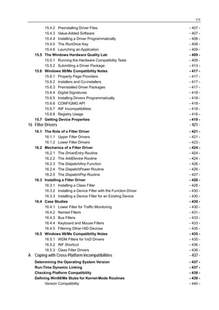
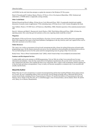
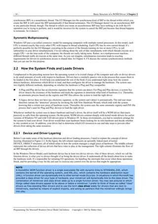
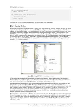
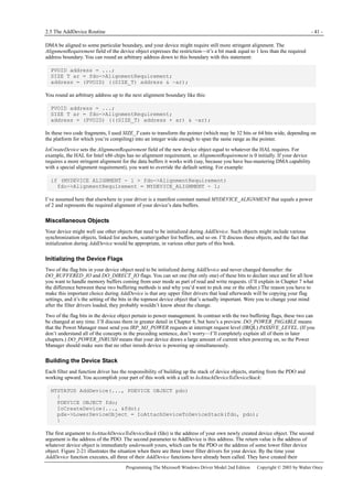
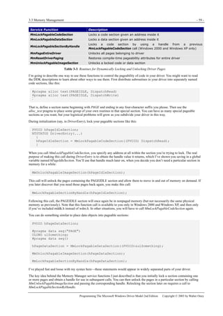
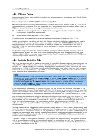
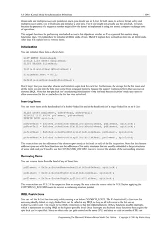
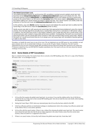
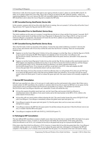
1.2.1 Windows XP Overview
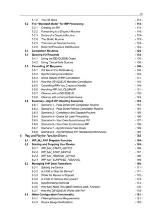
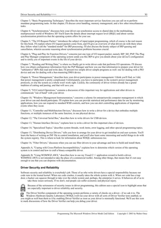
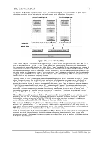
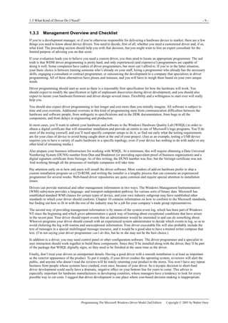
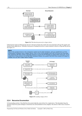
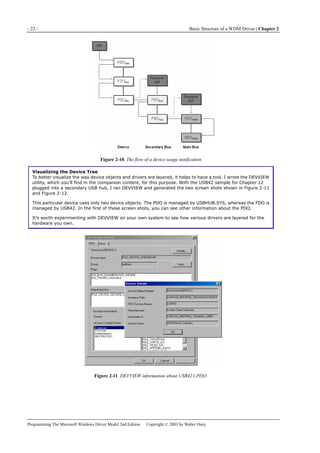
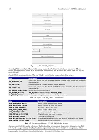
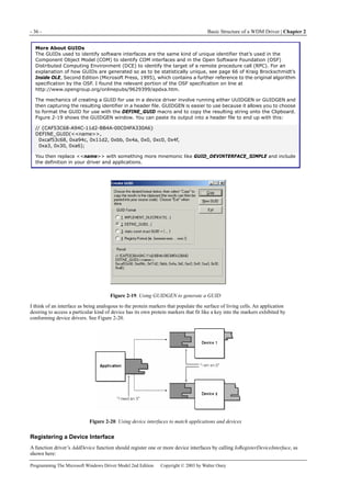
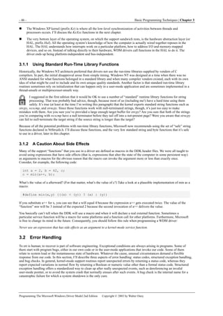
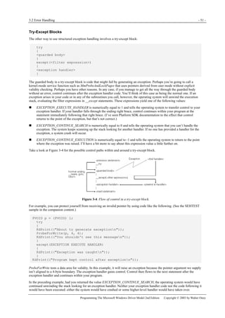
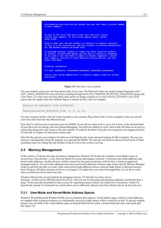
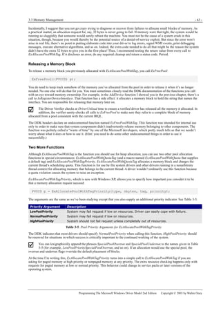
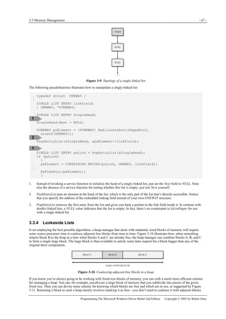
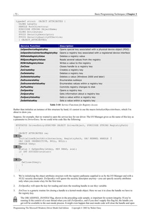
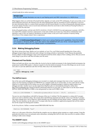
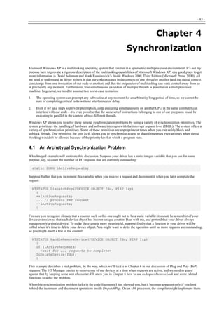
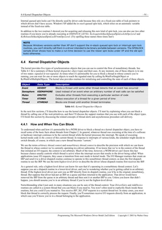
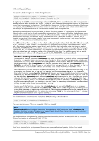
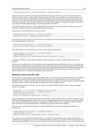
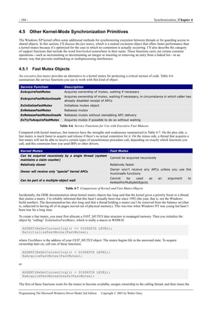
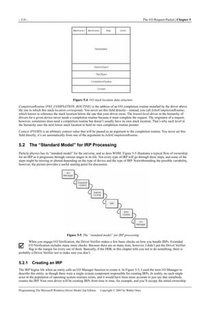
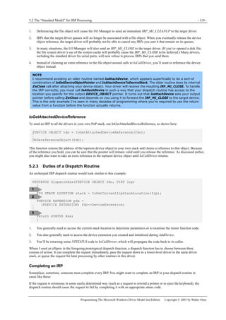
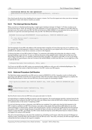
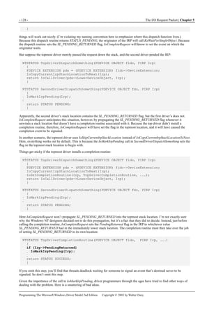
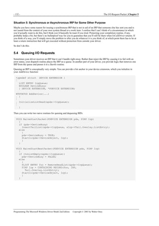
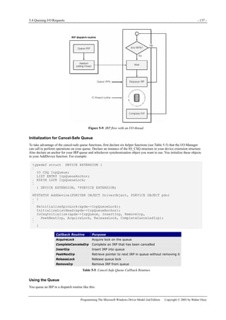
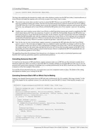
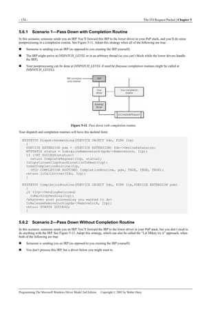
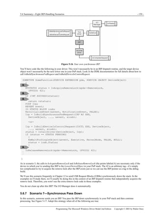
Figure 1-1. Windows XP architecture.
Figure 1-1 is a highly abbreviated functional diagram of the Windows XP operating system, wherein I emphasize the features
that are important to people who write device drivers. Every platform where Windows XP runs supports two modes of
execution. Software executes either in user mode or in kernel mode. A user-mode program that wants to, say, read some data
from a device would call an application programming interface (API) such as ReadFile. A subsystem module such as
KERNEL32.DLL implements this API by invoking a native API function such as NtReadFile. Refer to the sidebar for more
information about the native API.
We often say that NtReadFile is part of a system component called the I/O Manager. The term I/O Manager is perhaps a little
misleading because there isn’t any single executable module with that name. We need a name to use when discussing the
“cloud” of operating system services that surrounds our own driver, though, and this name is the one we usually pick.
Many routines serve a purpose similar to NtReadFile. They operate in kernel mode in order to service an application’s request
to interact with a device in some way. They all validate their parameters, thereby ensuring that they don’t inadvertently allow a
security breach by performing an operation, or accessing some data, that the user-mode program wouldn’t have been able to
perform or access by itself. They then create a data structure called an I/O request packet (IRP) that they pass to an entry point
in some device driver. In the case of an original ReadFile call, NtReadFile would create an IRP with the major function code
IRP_MJ_READ (a constant in a DDK [Driver Development Kit] header file). Processing details at this point can differ, but a
likely scenario is for a routine such as NtReadFile to return to the user-mode caller with an indication that the operation
described by the IRP hasn’t finished yet. The user-mode program might continue about its business and then wait for the
operation to finish, or it might wait immediately. Either way, the device driver proceeds independently of the application to
service the request.](https://image.slidesharecdn.com/2-programming-151105001030-lva1-app6892/85/2-programming-the-microsoft-windows-driver-model-2nd-edition-21-320.jpg)
![- 12 - Basic Structure of a WDM Driver | Chapter 2
Programming The Microsoft Windows Driver Model 2nd Edition Copyright © 2003 by Walter Oney
int main(int argc, char* argv[])
{
printf("Hello, world!n");
return 0;
}
This program consists of a main program named main and a library of helper routines, most of which we don’t explicitly call.
One of the helper routines, printf, prints a message to the standard output file. After compiling the source module containing
the main program and linking it with a runtime library containing printf and the other helper routines needed by the main
program, you would end up with an executable module that you might name HELLO.EXE. I’ll go so far as to call this module
by the grandiose name application because it’s identical in principle to every other application now in existence or hereafter
written. You could invoke this application from a command prompt this way:
C:>hello
Hello, world!
C:>
Here are some other common facts about applications:
Some of the helper routines an application uses come from a static library, from which the linkage editor extracts them as
part of the build process. printf is one of these functions.
Other helper routines are dynamically linked from system dynamic-link libraries (DLLs). For these routines, the linkage
editor places special import references in the executable file, and the runtime loader fixes up these references to point to
the actual system code. As a matter of fact, the entire Win32 API used by application programs is dynamically linked, so
you can see that dynamic linking is a very important concept in Windows programming.
Executable files can contain symbolic information that allows debuggers to associate runtime addresses with the original
source code.
Executable files can also contain resource data, such as dialog box templates, text strings, and version identification.
Placing this sort of data within the file is better than using separate auxiliary files because it avoids the problem of having
mismatched files.
The interesting thing about HELLO.EXE is that once the operating system gives it control, it doesn’t return until it’s
completely done with the task it performs. That’s a characteristic of every application you’ll ever use in Windows, actually. In
a console-mode application such as HELLO, the operating system initially transfers control to an initialization function that’s
part of the compiler’s runtime library. The initialization function eventually calls main to do the application’s work.
Graphical applications in Windows work in much the same way except that the main program is named WinMain instead of
main. WinMain operates a message pump to receive and dispatch messages to window procedures. It returns to the operating
system when the user closes the main window. If the only Windows applications you ever build use Microsoft Foundation
Classes (MFC), the WinMain procedure is buried in the library where you might never spot it, but rest assured it’s there.
More than one application can appear to be running simultaneously on a computer, even a computer that has just one central
processing unit. The operating system kernel contains a scheduler that gives short blocks of time, called time slices, to all the
threads that are currently eligible to run. An application begins life with a single thread and can create more if it wants. Each
thread has a priority, given to it by the system and subject to adjustment up and down for various reasons. At each decision
point, the scheduler picks the highest-priority eligible thread and gives it control by loading a set of saved register images,
including an instruction pointer, into the processor registers. A processor interrupt accompanies expiration of the thread’s time
slice. As part of handling the interrupt, the system saves the current register images, which can be restored the next time the
system decides to redispatch the same thread.
Instead of just waiting for its time slice to expire, a thread can block each time it initiates a time-consuming activity in another
thread until the activity finishes. This is better than spinning in a polling loop waiting for completion because it allows other
threads to run sooner than they would if the system had to rely solely on expiration of a time slice to turn its attention to some
other thread.
Now, I know you already knew what I just said. I just wanted to focus attention on the fact that an application is, at bottom, a
selfish thread that grabs the CPU and tries to hold on until it exits and that the operating system scheduler acts like a
playground monitor to make a bunch of selfish threads play well together.
2.1.2 Device Drivers
Like HELLO.EXE, a driver is also an executable file. It has the file extension .SYS, but structurally the disk file looks exactly
like any 32-bit Windows or console-mode application. Also like HELLO.EXE, a driver uses a number of helper routines, many
of which are dynamically linked from the operating system kernel or from a class driver or other supporting library. A driver
file can have symbolic debugging information and resource data too.](https://image.slidesharecdn.com/2-programming-151105001030-lva1-app6892/85/2-programming-the-microsoft-windows-driver-model-2nd-edition-30-320.jpg)
![- 28 - Basic Structure of a WDM Driver | Chapter 2
Programming The Microsoft Windows Driver Model 2nd Edition Copyright © 2003 by Walter Oney
The last general thing I want you to notice about the prototype is that it declares this function as returning an NTSTATUS value.
NTSTATUS is actually just a long integer, but you want to use the typedef name NTSTATUS instead of LONG so that people
understand your code better. A great many kernel-mode support routines return NTSTATUS status codes, and you’ll find a list
of them in the DDK header NTSTATUS.H. I’ll have a bit more to say about status codes in the next chapter; for now, just be
aware that your DriverEntry function will be returning a status code when it finishes.
2.4.1 Overview of DriverEntry
The first argument to DriverEntry is a pointer to a barely initialized driver object that represents your driver. A WDM driver’s
DriverEntry function will finish initializing this object and return. Non-WDM drivers have a great deal of extra work to
do—they must also detect the hardware for which they’re responsible, create device objects to represent the hardware, and do
all the configuration and initialization required to make the hardware fully functional. The relatively arduous detection and
configuration steps are handled automatically for WDM drivers by the PnP Manager, as I’ll discuss in Chapter 6. If you want
to know how a non-WDM driver initializes itself, consult Art Baker and Jerry Lozano’s The Windows 2000 Device Driver
Book (Prentice Hall, 2d ed., 2001) and Viscarola and Mason’s Windows NT Device Driver Development (Macmillan, 1998).
The second argument to DriverEntry is the name of the service key in the registry. This string is not persistent—you must copy
it if you plan to use it later. In a WDM driver, the only use I’ve ever made of this string is as part of WMI registration. (See
Chapter 10.)
A WDM driver’s main job in DriverEntry is to fill in the various function pointers in the driver object. These pointers indicate
to the operating system where to find the subroutines you’ve decided to place in your driver container. They include these
pointer members of the driver object:
DriverUnload
Set this to point to whatever cleanup routine you create. The I/O Manager will call this routine just prior to unloading the
driver. If there’s nothing to clean up, you need to have a DriverUnload function for the system to be able to unload your
driver dynamically.
DriverExtension->AddDevice
Set this to point to your AddDevice function. The PnP Manager will call AddDevice once for each hardware instance
you’re responsible for. Since AddDevice is so important to the way WDM drivers work, I’ve devoted the next main
section of this chapter (“The AddDevice Routine”) to explaining what it does.
DriverStartIo
If your driver uses the standard method of queuing I/O requests, you’ll set this member of the driver object to point to
your StartIo routine. Don’t worry (yet, that is) if you don’t understand what I mean by the “standard” queuing method; all
will become clear in Chapter 5, where you’ll discover that WDM drivers shouldn’t use it.
MajorFunction
The I/O Manager initializes this vector of function pointers to point to a dummy dispatch function that fails every request.
You’re presumably going to be handling certain types of IRPs—otherwise, your driver is basically going to be deaf and
inert—so you’ll set at least some of these pointers to your own dispatch functions. Chapter 5 discusses IRPs and dispatch
functions in detail. For now, all you need to know is that you must handle two kinds of IRPs and that you’ll probably be
handling several other kinds as well.
A nearly complete DriverEntry routine will, then, look like this:
extern "C" NTSTATUS DriverEntry(IN PDRIVER_OBJECT DriverObject,
IN PUNICODE_STRING RegistryPath)
{
DriverObject->DriverUnload = DriverUnload;
DriverObject->DriverExtension->AddDevice = AddDevice;
DriverObject->MajorFunction[IRP_MJ_PNP] = DispatchPnp;
DriverObject->MajorFunction[IRP_MJ_POWER] = DispatchPower;
DriverObject->MajorFunction[IRP_MJ_SYSTEM_CONTROL] = DispatchWmi;
servkey.Buffer = (PWSTR) ExAllocatePool(PagedPool,
RegistryPath->Length + sizeof(WCHAR));
if (!servkey.Buffer)
return STATUS_INSUFFICIENT_RESOURCES;
servkey.MaximumLength = RegistryPath->Length + sizeof(WCHAR);
RtlCopyUnicodeString(&servkey, RegistryPath);
servkey.Buffer[RegistryPath->Length/sizeof(WCHAR)] = 0;
return STATUS_SUCCESS;](https://image.slidesharecdn.com/2-programming-151105001030-lva1-app6892/85/2-programming-the-microsoft-windows-driver-model-2nd-edition-46-320.jpg)
![2.5 The AddDevice Routine - 35 -
Programming The Microsoft Windows Driver Model 2nd Edition Copyright © 2003 by Walter Oney
I’ll discuss the use of RtlInitUnicodeString in the next chapter.
NOTE
Starting in Windows XP, device object names are case insensitive. In Windows 98/Me and in Windows 2000,
they are case sensitive. Be sure to spell Device exactly as shown if you want your driver to be portable across
all the systems. Note also the spelling of DosDevices, particularly if your mother tongue doesn’t inflect the
plural form of nouns!
Conventionally, drivers assign their device objects a name by concatenating a string naming their device type (“Simple” in this
code fragment) with a 0-based integer denoting an instance of that type. In general, you don’t want to hard-code a name as I
just did—you want to compose it dynamically using string-manipulation functions like the following:
UNICODE_STRING devname;
static LONG lastindex = -1;
LONG devindex = InterlockedIncrement(&lastindex);
WCHAR name[32];
_snwprintf(name, arraysize(name), L"DeviceSIMPLE%2.2d",devindex);
RtlInitUnicodeString(&devname, name);
IoCreateDevice(...);
I’ll explain the various service functions used in this code fragment in the next couple of chapters. The instance number you
derive for private device types might as well be a static variable, as shown in the code fragment.
Notes on Device Naming
The GLOBAL?? directory used to be named DosDevices. The change was made to move the often-searched
directory of user-mode names to the front of the alphabetical list of directories. Windows 98/Me doesn’t
recognize the name ?? or GLOBAL??.
Windows 2000 defines a symbolic link named DosDevices that points to the ?? directory. Windows XP treats
DosDevices differently depending on the process context at the time you create an object. If you create an
object, such as a symbolic link, in a system thread, DosDevices refers to GLOBAL??, and you end up with a
global name. If you create an object in a user thread, DosDevices refers to ??, and you end up with a
session-specific name. In most situations, a device driver creates symbolic links in its AddDevice function,
which runs in a system thread, and so ends up with globally named objects in all WDM environments simply by
putting the symbolic link in DosDevices. If you create a symbolic link at another time, you should use
GLOBAL?? in Windows XP and DosDevices in earlier systems. See Appendix A for a discussion of how to
distinguish between WDM platforms.
A quick-and-dirty shortcut for testing is to name your device object in the DosDevices directory, as many of the
sample drivers in the companion content do. A production driver should name the device object in Device,
however, to avoid the possibility of creating an object that ought to be global in a session-private namespace.
In previous versions of Windows NT, drivers for certain classes of devices (notably disks, tapes, serial ports, and
parallel ports) called IoGetConfigurationInformation to obtain a pointer to a global table containing counts of
devices in each of these special classes. A driver would use the current value of the counter to compose a name
like Harddisk0, Tape1, and so on and would also increment the counter. WDM drivers don’t need to use this
service function or the table it returns, however. Constructing names for the devices in these classes is now the
responsibility of a Microsoft type-specific class driver (such as DISK.SYS).
Device Interfaces
The older method of naming I just discussed—naming your device object and creating a symbolic link name that applications
can use—has two major problems. We’ve already discussed the security implications of giving your device object a name. In
addition, the author of an application that wants to access your device has to know the scheme you adopted to name your
devices. If you’re the only one writing the applications that will be accessing your hardware, that’s not much of a problem. But
if many different companies will be writing applications for your hardware, and especially if many hardware companies are
making similar devices, devising a suitable naming scheme is difficult.
To solve these problems, WDM introduces a new naming scheme for devices that is language-neutral, easily extensible, usable
in an environment with many hardware and software vendors, and easily documented. The scheme relies on the concept of a
device interface, which is basically a specification for how software can access hardware. A device interface is uniquely
identified by a 128-bit GUID. You can generate GUIDs by running the Platform SDK utilities UUIDGEN or GUIDGEN—both
utilities generate the same kind of number, but they output the result in different formats. The idea is that some industry group
gets together to define a standard way of accessing a certain kind of hardware. As part of the standard-making process,
someone runs GUIDGEN and publishes the resulting GUID as the identifier that will be forever after associated with that
interface standard.](https://image.slidesharecdn.com/2-programming-151105001030-lva1-app6892/85/2-programming-the-microsoft-windows-driver-model-2nd-edition-53-320.jpg)
![- 38 - Basic Structure of a WDM Driver | Chapter 2
Programming The Microsoft Windows Driver Model 2nd Edition Copyright © 2003 by Walter Oney
public:
CDeviceList(const GUID& guid);
~CDeviceList();
GUID m_guid;
CArray<CDeviceListEntry, CDeviceListEntry&> m_list;
int Initialize();
};
The classes rely on the CString class and CArray template class that are part of the Microsoft Foundation Classes (MFC)
framework. The constructors for these two classes simply copy their arguments into the obvious data members:
CDeviceList::CDeviceList(const GUID& guid)
{
m_guid = guid;
}
CDeviceListEntry::CDeviceListEntry(LPCTSTR linkname,LPCTSTR friendlyname)
{
m_linkname = linkname;
m_friendlyname = friendlyname;
}
All the interesting work occurs in the CDeviceList::Initialize function. The executive overview of what it does is this: it will
enumerate all of the devices that expose the interface whose GUID was supplied to the constructor. For each such device, it
will determine a friendly name that we’re willing to show to an unsuspecting end user. Finally it will return the number of
devices it found. Here’s the code for this function:
int CDeviceList::Initialize()
{
HDEVINFO info = SetupDiGetClassDevs(&m_guid, NULL, NULL,
DIGCF_PRESENT │ DIGCF_INTERFACEDEVICE);
if (info == INVALID_HANDLE_VALUE)
return 0;
SP_INTERFACE_DEVICE_DATA ifdata;
ifdata.cbSize = sizeof(ifdata);
DWORD devindex;
for (devindex = 0;
SetupDiEnumDeviceInterfaces(info,NULL, &m_guid, devindex, &ifdata);
++devindex)
{
DWORD needed;
SetupDiGetDeviceInterfaceDetail(info, &ifdata, NULL, 0, &needed, NULL);
PSP_INTERFACE_DEVICE_DETAIL_DATA detail =
(PSP_INTERFACE_DEVICE_DETAIL_DATA) malloc(needed);
detail->cbSize = sizeof(SP_INTERFACE_DEVICE_DETAIL_DATA);
SP_DEVINFO_DATA did = {sizeof(SP_DEVINFO_DATA)};
SetupDiGetDeviceInterfaceDetail(info, &ifdata, detail, needed, NULL, &did));
TCHAR fname[256];
if (!SetupDiGetDeviceRegistryProperty(info, &did,
SPDRP_FRIENDLYNAME, NULL, (PBYTE) fname,
sizeof(fname), NULL)
&& !SetupDiGetDeviceRegistryProperty(info, &did,
SPDRP_DEVICEDESC,
NULL, (PBYTE) fname, sizeof(fname), NULL))
_tcsncpy(fname, detail->DevicePath, 256);
fname[255] = 0;
CDeviceListEntry e(detail->DevicePath, fname);
free((PVOID) detail);
m_list.Add(e);
}](https://image.slidesharecdn.com/2-programming-151105001030-lva1-app6892/85/2-programming-the-microsoft-windows-driver-model-2nd-edition-56-320.jpg)


![3.4 String Handling - 69 -
Programming The Microsoft Windows Driver Model 2nd Edition Copyright © 2003 by Walter Oney
After reserving storage for the lookaside list object somewhere, you call the appropriate initialization routine:
PPAGED_LOOKASIDE_LIST pagedlist;
PNPAGED_LOOKASIDE_LIST nonpagedlist;
ExInitializePagedLookasideList(pagedlist, Allocate, Free, 0, blocksize, tag, 0);
ExInitializeNPagedLookasideList(nonpagedlist, Allocate, Free,
0, blocksize, tag, 0);
(The only difference between the two examples is the spelling of the function name and the first argument.)
The first argument to either of these functions points to the [N]PAGED_LOOKASIDE_LIST object for which you’ve already
reserved space. Allocate and Free are pointers to routines you can write to allocate or release memory from a random heap.
You can use NULL for either or both of these parameters, in which case ExAllocatePoolWithTag and ExFreePool will be used,
respectively. The blocksize parameter is the size of the memory blocks you will be allocating from the list, and tag is the 32-bit
tag value you want placed in front of each such block. The two zero arguments are placeholders for values that you supplied in
previous versions of Windows NT but that the system now determines on its own; these values are flags to control the type of
allocation and the depth of the lookaside list.
To allocate a memory block from the list, call the appropriate AllocateFrom function:
PVOID p = ExAllocateFromPagedLookasideList(pagedlist);
PVOID q = ExAllocateFromNPagedLookasideList(nonpagedlist);
To put a block back onto the list, call the appropriate FreeTo function:
ExFreeToPagedLookasideList(pagedlist, p);
ExFreeToNPagedLookasideList(nonpagedlist, q);
Finally, to destroy a list, call the appropriate Delete function:
ExDeletePagedLookasidelist(pagedlist);
ExDeleteNPagedLookasideList(nonpagedlist);
It is very important for you to explicitly delete a lookaside list before allowing the list object to pass out of scope. I’m
told that a common programming mistake is to place a lookaside list object in a device extension and then forget to
delete the object before calling IoDeleteDevice. If you make this mistake, the next time the system runs through its list
of lookaside lists to tune their depths, it will put its foot down on the spot where your list object used to be, probably with bad
results.
3.4 String Handling
WDM drivers can work with string data in any of four formats:
A Unicode string, normally described by a UNICODE_STRING structure, contains 16-bit characters. Unicode has
sufficient code points to accommodate the language scripts used on this planet. A whimsical attempt to standardize code
points for the Klingon language, reported in the first edition, has been rejected. A reader of the first edition sent me the
following e-mail comment about this:
I suspect this is rude, and possibly obscene.
An ANSI string, normally described by an ANSI_STRING structure, contains 8-bit characters. A variant is an
OEM_STRING, which also describes a string of 8-bit characters. The difference between the two is that an OEM string
has characters whose graphic depends on the current code page, whereas an ANSI string has characters whose graphic is
independent of code page. WDM drivers won’t normally deal with OEM strings because they would have to originate in
user mode, and some other kernel-mode component will have already translated them into Unicode strings by the time
the driver sees them.
A null-terminated string of characters. You can express constants using normal C syntax, such as “Hello, world!” Strings
employ 8-bit characters of type CHAR, which are assumed to be from the ANSI character set. The characters in string
constants originate in whatever editor you used to create your source code. If you use an editor that relies on the
then-current code page to display graphics in the editing window, be aware that some characters might have a different
meaning when treated as part of the Windows ANSI character set.](https://image.slidesharecdn.com/2-programming-151105001030-lva1-app6892/85/2-programming-the-microsoft-windows-driver-model-2nd-edition-87-320.jpg)
![- 74 - Basic Programming Techniques | Chapter 3
Programming The Microsoft Windows Driver Model 2nd Edition Copyright © 2003 by Walter Oney
for the KEY_VALUE_PARTIAL_INFORMATION structure we’re trying to retrieve. The second call retrieves the information. I
left the error checking in this code fragment because the errors didn’t work out in practice the way I expected them to. In
particular, I initially guessed that the first call to ZwQueryValueKey would return STATUS_BUFFER_TOO_SMALL (since I
passed it a zero-length buffer). It didn’t do that, though. The important failure code is
STATUS_OBJECT_NAME_NOT_FOUND, which indicates that the value doesn’t actually exist. Hence, I test for that value
only. If there’s some other error that prevents ZwQueryValueKey from working, the second call will uncover it.
NOTE
The reason for trimming the size to PAGE_SIZE is to impose a reasonableness limit on the amount of
memory you allocate. If a malicious user were able to gain access to the key from which you’re reading, he or
she could replace the ImagePath value with an arbitrary amount of data. Your driver could then become an
unwitting accomplice to a denial of service attack by consuming mass quantities of memory. Now, drivers
ordinarily deal with registry keys that only administrators can modify, and an administrator has many other
ways of attacking the system. It’s nonetheless good to provide a defense in depth against all forms of attack.
The so-called “partial” information structure you retrieve in this way contains the value’s data and a description of its data
type:
typedef struct _KEY_VALUE_PARTIAL_INFORMATION {
ULONG TitleIndex;
ULONG Type;
ULONG DataLength;
UCHAR Data[1];
} KEY_VALUE_PARTIAL_INFORMATION, *PKEY_VALUE_PARTIAL_INFORMATION;
Type is one of the registry data types listed in Table 3-12. (Additional data types are possible but not interesting to device
drivers.) DataLength is the length of the data value, and Data is the data itself. TitleIndex has no relevance to drivers. Here are
some useful facts to know about the various data types:
REG_DWORD is a 32-bit unsigned integer in whatever format (big-endian or little-endian) is natural for the platform.
REG_SZ describes a null-terminated Unicode string value. The null terminator is included in the DataLength count.
To expand a REG_EXPAND_SZ value by substituting environment variables, you should use RtlQueryRegistryValues as
your method of interrogating the registry. The internal routines for accessing environment variables aren’t documented or
exposed for use by drivers.
RtlQueryRegistryValues is also a good way to interrogate REG_MULTI_SZ values in that it will call your designated
callback routine once for each of the potentially many strings.
NOTE
Notwithstanding the apparent utility of RtlQueryRegistryValues, I’ve avoided using it ever since it caused a
crash in one of my drivers. Apparently, the value I was reading required the function to call a helper function
that was placed in the initialization section of the kernel and that was, therefore, no longer present.
Data TypeConstant Description
REG_BINARY Variable-length binary data
REG_DWORD Unsigned long integer in natural format for the platform
REG_EXPAND_SZ
Null-terminated Unicode string containing %-escapes for environment variable
names
REG_MULTI_SZ One or more null-terminated Unicode strings, followed by an extra null
REG_SZ Null-terminated Unicode string
Table 3-12. Types of Registry Values Useful to WDM Drivers
To set a registry value, you must have KEY_SET_VALUE access to the parent key. I used KEY_READ earlier, which wouldn’t
give you such access. You could use KEY_WRITE or KEY_ALL_ACCESS, although you thereby gain more than the necessary
permission. Then call ZwSetValueKey. For example:
RtlInitUnicodeString(&valname, L"TheAnswer");
ULONG value = 42;
ZwSetValueKey(hkey, &valname, 0, REG_DWORD, &value, sizeof(value));
Deleting Subkeys or Values
To delete a value in an open key, you can use RtlDeleteRegistryValue in the following special way:](https://image.slidesharecdn.com/2-programming-151105001030-lva1-app6892/85/2-programming-the-microsoft-windows-driver-model-2nd-edition-92-320.jpg)
![3.5 Miscellaneous Programming Techniques - 75 -
Programming The Microsoft Windows Driver Model 2nd Edition Copyright © 2003 by Walter Oney
RtlDeleteRegistryValue(RTL_REGISTRY_HANDLE, (PCWSTR) hkey, L"TheAnswer");
RtlDeleteRegistryValue is a general service function whose first argument can designate one of several special places in the
registry. When you use RTL_REGISTRY_HANDLE, as I did in this example, you indicate that you already have an open handle
to the key within which you want to delete a value. You specify the key (with a cast to make the compiler happy) as the second
argument. The third and final argument is the null-terminated Unicode name of the value you want to delete. This is one time
when you don’t have to create a UNICODE_STRING structure to describe the string.
In Windows 2000 and later, you can use ZwDeleteValueKey to delete a value (it’s an oversight that this function isn’t
documented in the DDK):
UNICODE_STRING valname;
RtlInitUnicodeString(&valname, L"TheAnswer");
ZwDeleteValueKey(hkey, &valname);
You can delete only those keys that you’ve opened with at least DELETE permission (which you get with KEY_ALL_ACCESS).
You call ZwDeleteKey:
ZwDeleteKey(hkey);
The key lives on until all handles are closed, but subsequent attempts to open a new handle to the key or to access the key by
using any currently open handle will fail with STATUS_KEY_DELETED. Since you have an open handle at this point, you
must be sure to call ZwClose sometime. (The DDK documentation entry for ZwDeleteKey says the handle becomes invalid. It
doesn’t—you must still close it by calling ZwClose.)
Enumerating Subkeys or Values
A complicated activity you can carry out with an open registry key is to enumerate the elements (subkeys and values) that the
key contains. To do this, you’ll first call ZwQueryKey to determine a few facts about the subkeys and values, such as their
number, the length of the largest name, and so on. ZwQueryKey has an argument that indicates which of three types of
information you want to retrieve about the key. These types are named basic, node, and full. To prepare for an enumeration,
you’d be interested first in the full information:
typedef struct _KEY_FULL_INFORMATION {
LARGE_INTEGER LastWriteTime;
ULONG TitleIndex;
ULONG ClassOffset;
ULONG ClassLength;
ULONG SubKeys;
ULONG MaxNameLen;
ULONG MaxClassLen;
ULONG Values;
ULONG MaxValueNameLen;
ULONG MaxValueDataLen;
WCHAR Class[1];
} KEY_FULL_INFORMATION, *PKEY_FULL_INFORMATION;
This structure is actually of variable length since Class[0] is just the first character of the class name. It’s customary to make
one call to find out how big a buffer you need to allocate and a second call to get the data, as follows:
ULONG size;
ZwQueryKey(hkey, KeyFullInformation, NULL, 0, &size);
size = min(size, PAGE_SIZE);
PKEY_FULL_INFORMATION fip = (PKEY_FULL_INFORMATION)
ExAllocatePool(PagedPool, size);
ZwQueryKey(hkey, KeyFullInformation, fip, size, &size);
Were you now interested in the subkeys of your registry key, you could perform the following loop calling ZwEnumerateKey:
for (ULONG i = 0; i < fip->SubKeys; ++i)
{
ZwEnumerateKey(hkey, i, KeyBasicInformation, NULL, 0, &size);
size = min(size, PAGE_SIZE);
PKEY_BASIC_INFORMATION bip = (PKEY_BASIC_INFORMATION)
ExAllocatePool(PagedPool, size);
ZwEnumerateKey(hkey, i, KeyBasicInformation, bip, size, &size);
<do something with bip->Name>](https://image.slidesharecdn.com/2-programming-151105001030-lva1-app6892/85/2-programming-the-microsoft-windows-driver-model-2nd-edition-93-320.jpg)
![- 76 - Basic Programming Techniques | Chapter 3
Programming The Microsoft Windows Driver Model 2nd Edition Copyright © 2003 by Walter Oney
ExFreePool(bip);
}
The key fact you discover about each subkey is its name, which shows up as a counted Unicode string in the
KEY_BASIC_INFORMATION structure you retrieve inside the loop:
typedef struct _KEY_BASIC_INFORMATION {
LARGE_INTEGER LastWriteTime;
ULONG Type;
ULONG NameLength;
WCHAR Name[1];
} KEY_BASIC_INFORMATION, *PKEY_BASIC_INFORMATION;
The name isn’t null-terminated; you must use the NameLength member of the structure to determine its length. Don’t forget
that the length is in bytes! The name isn’t the full registry path either; it’s just the name of the subkey within whatever key
contains it. This is actually lucky because you can easily open a subkey given its name and an open handle to its parent key.
To accomplish an enumeration of the values in an open key, employ the following method:
ULONG maxlen = fip->MaxValueNameLen + sizeof(KEY_VALUE_BASIC_INFORMATION);
maxlen = min(maxlen, PAGE_SIZE);
PKEY_VALUE_BASIC_INFORMATION vip = (PKEY_VALUE_BASIC_INFORMATION)
ExAllocatePool(PagedPool, maxlen);
for (ULONG i = 0; i < fip->Values; ++i)
{
ZwEnumerateValueKey(hkey, i, KeyValueBasicInformation, vip, maxlen, &size);
<do something with vip->Name>
}
ExFreePool(vip);
Allocate space for the largest possible KEY_VALUE_BASIC_INFORMATION structure that you’ll ever retrieve based on the
MaxValueNameLen member of the KEY_FULL_INFORMATION structure. Inside the loop, you’ll want to do something with
the name of the value, which comes to you as a counted Unicode string in this structure:
typedef struct _KEY_VALUE_BASIC_INFORMATION {
ULONG TitleIndex;
ULONG Type;
ULONG NameLength;
WCHAR Name[1];
} KEY_VALUE_BASIC_INFORMATION, *PKEY_VALUE_BASIC_INFORMATION;
Once again, having the name of the value and an open handle to its parent key is just what you need to retrieve the value, as
shown in the preceding section.
There are variations on ZwQueryKey and on these two enumeration functions that I haven’t discussed. You can, for example,
obtain full information about a subkey when you call ZwEnumerateKey. I showed you only how to get the basic information
that includes the name. You can retrieve data values only, or names plus data values, from ZwEnumerateValueKey. I showed
you only how to get the name of a value.
3.5.2 Accessing Files
It’s sometimes useful to be able to read and write regular disk files from inside a WDM driver. Perhaps you need to download a
large amount of microcode to your hardware, or perhaps you need to create your own extensive log of information for some
purpose. There’s a set of ZwXxx routines to help you do these things.
File access via the ZwXxx routines require you be running at PASSIVE_LEVEL (see the next chapter) in a thread that can
safely be suspended. In practice, the latter requirement means that you must not have disabled Asynchronous Procedure Calls
(APCs) by calling KeEnterCriticalRegion. You’ll read in the next chapter that some synchronization primitives require you to
raise the IRQL above PASSIVE_LEVEL or to disable APCs. Just bear in mind that those synchronization primitives and file
access are incompatible.
The first step in accessing a disk file is to open a handle by calling ZwCreateFile. The full description of this function in the
DDK is relatively complex because of all the ways in which it can be used. I’m going to show you two simple scenarios,
however, that are useful if you just want to read or write a file whose name you already know.
Sample Code
The FILEIO sample driver in the companion content illustrates calls to some of the ZwXxx functions discussed
in this section. This particular sample is valuable because it provides workarounds for the platform](https://image.slidesharecdn.com/2-programming-151105001030-lva1-app6892/85/2-programming-the-microsoft-windows-driver-model-2nd-edition-94-320.jpg)
![- 100 - Synchronization | Chapter 4
Programming The Microsoft Windows Driver Model 2nd Edition Copyright © 2003 by Walter Oney
up from a wait. Your DPC routine would have the following skeletal appearance:
VOID DpcRoutine(PKDPC dpc, PVOID context, PVOID junk1, PVOID junk2)
{
}
For what it’s worth, even when you supply a DPC argument to KeSetTimer or KeSetTimerEx, you can still call KeWaitXxx to
wait at PASSIVE_LEVEL or APC_LEVEL if you want. On a single-CPU system, the DPC would occur before the wait could
finish because it executes at a higher IRQL.
Synchronization Timers
Like event objects, timer objects come in both notification and synchronization flavors. A notification timer allows any number
of waiting threads to proceed once it expires. A synchronization timer, by contrast, allows only a single thread to proceed. Once
a thread’s wait is satisfied, the timer switches to the not-signaled state. To create a synchronization timer, you must use the
extended form of the initialization service function:
ASSERT(KeGetCurrentIrql() <= DISPATCH_LEVEL);
KeInitializeTimerEx(timer, SynchronizationTimer);
SynchronizationTimer is one of the values of the TIMER_TYPE enumeration. The other value is NotificationTimer.
If you use a DPC with a synchronization timer, think of queuing the DPC as being an extra thing that happens when the timer
expires. That is, expiration puts the timer in the signaled state and queues a DPC. One thread can be released as a result of the
timer being signaled.
The only use I’ve ever found for a synchronization timer is when you want a periodic timer (see the next section).
Periodic Timers
So far, I’ve discussed only timers that expire exactly once. By using the extended set timer function, you can also request a
periodic timeout:
ASSERT(KeGetCurrentIrql() <= DISPATCH_LEVEL);
LARGE_INTEGER duetime;
BOOLEAN wascounting = KeSetTimerEx(timer, duetime, period, dpc);
Here period is a periodic timeout, expressed in milliseconds (ms), and dpc is an optional pointer to a KDPC object. A timer of
this kind expires once at the due time and periodically thereafter. To achieve exact periodic expiration, specify the same
relative due time as the interval. Specifying a zero due time causes the timer to immediately expire, whereupon the periodic
behavior takes over. It often makes sense to start a periodic timer in conjunction with a DPC object, by the way, because doing
so allows you to be notified without having to repeatedly wait for the timeout.
Be sure to call KeCancelTimer to cancel a periodic timer before the KTIMER object or the DPC routine disappears
from memory. It’s quite embarrassing to let the system unload your driver and, 10 nanoseconds later, call your
nonexistent DPC routine. Not only that, but it causes a bug check. These problems are so hard to debug that the Driver
Verifier makes a special check for releasing memory that contains an active KTIMER.
An Example
One use for kernel timers is to conduct a polling loop in a system thread dedicated to the task of repeatedly checking a device
for activity. Not many devices nowadays need to be served by a polling loop, but yours may be one of the few exceptions. I’ll
discuss this subject in Chapter 14, and the companion content includes a sample driver (POLLING) that illustrates all of the
concepts involved. Part of that sample is the following loop that polls the device at fixed intervals. The logic of the driver is
such that the loop can be broken by setting a kill event. Consequently, the driver uses KeWaitForMultipleObjects. The code is
actually a bit more complicated than the following fragment, which I’ve edited to concentrate on the part related to the timer:
VOID PollingThreadRoutine(PDEVICE_EXTENSION pdx)
{
NTSTATUS status;
KTIMER timer;
KeInitializeTimerEx(&timer, SynchronizationTimer);
PVOID pollevents[] = {
(PVOID) &pdx->evKill,](https://image.slidesharecdn.com/2-programming-151105001030-lva1-app6892/85/2-programming-the-microsoft-windows-driver-model-2nd-edition-118-320.jpg)
![- 108 - Synchronization | Chapter 4
Programming The Microsoft Windows Driver Model 2nd Edition Copyright © 2003 by Walter Oney
InterlockedExchange(&lock, 0);
}
ExInterlockedXxx Functions
Each of the ExInterlockedXxx functions requires that you create and initialize a spin lock before you call it. Note that the
operands of these functions must all be in nonpaged memory because the functions operate on the data at elevated IRQL.
ExInterlockedAddLargeInteger adds two 64-bit integers and returns the previous value
of the target:
LARGE_INTEGER value, increment;
KSPIN_LOCK spinlock;
LARGE_INTEGER prev = ExInterlockedAddLargeInteger(&value, increment, &spinlock);
Value is the target of the addition and one of the operands. Increment is an integer operand that’s added to the target. Spinlock
is a spin lock that you previously initialized. The return value is the target’s value before the addition. In other words, the
operation of this function is similar to the following function except that it occurs under protection of the spin lock:
__int64 AddLargeInteger(__int64* pvalue, __int64 increment)
{
__int64 prev = *pvalue;
*pvalue += increment;
return prev;
}
Note that the return value is the preaddition value, which contrasts with the postincrement return from InterlockedExchange
and similar functions. (Also, not all compilers support the __int64 integer data type, and not all computers can perform a 64-bit
addition operation using atomic instructions.)
ExInterlockedAddUlong is analogous to ExInterlockedAddLargeInteger except that it works with 32-bit unsigned integers:
ULONG value, increment;
KSPIN_LOCK spinlock;
ULONG prev = ExInterlockedAddUlong(&value, increment, &spinlock);
This function likewise returns the preaddition value of the target of the operation.
ExInterlockedAddLargeStatistic is similar to ExInterlockedAddUlong in that it adds a 32-bit value to a 64-bit value:
VOID ExInterlockedAddLargeStatistic(PLARGE_INTEGER Addend, ULONG Increment);
This new function is faster than ExInterlockedAddUlong because it doesn’t need to return the preincrement value of the
Addend variable. It therefore doesn’t need to employ a spin lock for synchronization. The atomicity provided by this function
is, however, only with respect to other callers of the same function. In other words, if you had code on one CPU calling
ExInterlockedAddLargeStatistic at the same time as code on another CPU was accessing the Addend variable for either reading
or writing, you could get inconsistent results. I can explain why this is so by showing you this paraphrase of the Intel x86
implementation of the function (not the actual source code):
mov eax, Addend
mov ecx, Increment
lock add [eax], ecx
lock adc [eax+4], 0
This code works correctly for purposes of incrementing the Addend because the lock prefixes guarantee atomicity of each
addition operation and because no carries from the low-order 32 bits can ever get lost. The instantaneous value of the 64-bit
Addend isn’t always consistent, however, because an incrementer might be poised between the ADD and the ADC just at the
instant someone makes a copy of the complete 64-bit value. Therefore, even a caller of ExInterlockedCompareExchange64 on
another CPU could obtain an inconsistent value.
4.5.3 Interlocked List Access
The Windows NT executive offers three sets of support functions for dealing with linked lists in a thread-safe and
multiprocessor-safe way. These functions support doubly-linked lists, singly-linked lists, and a special kind of singly-linked list
called an S-List. I discussed noninterlocked doubly-linked and singly-linked lists in the preceding chapter. To close this chapter
on synchronization within WDM drivers, I’ll explain how to use these interlocked accessing primitives.
If you need the functionality of a FIFO queue, you should use a doubly-linked list. If you need the functionality of a](https://image.slidesharecdn.com/2-programming-151105001030-lva1-app6892/85/2-programming-the-microsoft-windows-driver-model-2nd-edition-126-320.jpg)
![5.1 Data Structures - 113 -
Programming The Microsoft Windows Driver Model 2nd Edition Copyright © 2003 by Walter Oney
Tail.Overlay is a structure within a union that contains several members potentially useful to a WDM driver. Refer to Figure
5-2 for a map of the Tail union. In the figure, items at the same level as you read left to right are alternatives within a union,
while the vertical dimension portrays successive locations within a structure. Tail.Overlay.DeviceQueueEntry
(KDEVICE_QUEUE_ENTRY) and Tail.Overlay.DriverContext (PVOID[4]) are alternatives within an unnamed union within
Tail.Overlay. The I/O Manager uses DeviceQueueEntry as a linking field within the standard queue of requests for a device.
The cancel-safe queuing routines IoCsqXxx use the last entry in the DriverContext array. If these system usages don’t get in
your way, at moments when the IRP is not in some queue that uses this field and when you own the IRP, you can use the four
pointers in DriverContext in any way you please. Tail.Overlay.ListEntry (LIST_ENTRY) is available for you to use as a linking
field for IRPs in any private queue you choose to implement.
CurrentLocation (CHAR) and Tail.Overlay.CurrentStackLocation (PIO_STACK_LOCATION) aren’t documented for use by
drivers because support functions such as IoGetCurrentIrpStackLocation can be used instead. During debugging, however, it
might help you to realize that CurrentLocation is the index of the current I/O stack location and CurrentStackLocation is a
pointer to it.
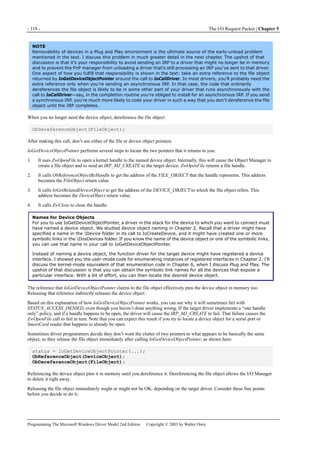
5.1.2 The I/O Stack
Whenever any kernel-mode program creates an IRP, it also creates an associated array of IO_STACK_LOCATION structures:
one stack location for each of the drivers that will process the IRP and sometimes one more stack location for the use of the
originator of the IRP. (See Figure 5-3.) A stack location contains type codes and parameter information for the IRP as well as
the address of a completion routine. Refer to Figure 5-4 for an illustration of the stack structure.
Figure 5-3. Parallelism between driver and I/O stacks.
NOTE
I’ll discuss the mechanics of creating IRPs a bit further on in this chapter. It helps to know right now that the
StackSize field of a DEVICE_OBJECT indicates how many locations to reserve for an IRP sent to that device’s
driver.
MajorFunction (UCHAR) is the major function code associated with this IRP. This code is a value such as IRP_MJ_READ that
corresponds to one of the dispatch function pointers in the MajorFunction table of a driver object. Because the code is in the
I/O stack location for a particular driver, it’s conceivable that an IRP could start life as an IRP_MJ_READ (for example) and be
transformed into something else as it progresses down the stack of drivers. I’ll show you examples in Chapter 12 of how a
USB driver changes the personality of a read or write request into an internal control operation to submit the request to the
USB bus driver.
MinorFunction (UCHAR) is a minor function code that further identifies an IRP belonging to a few major function classes.
IRP_MJ_PNP requests, for example, are divided into a dozen or so subtypes with minor function codes such as
IRP_MN_START_DEVICE, IRP_MN_REMOVE_DEVICE, and so on.
Parameters (union) is a union of substructures, one for each type of request that has specific parameters. The substructures
include, for example, Create (for IRP_MJ_CREATE requests), Read (for IRP_MJ_READ requests), and StartDevice (for the
IRP_MN_START_DEVICE subtype of IRP_MJ_PNP).
DeviceObject (PDEVICE_OBJECT) is the address of the device object that corresponds to this stack entry. IoCallDriver fills
in this field.
FileObject (PFILE_OBJECT) is the address of the kernel file object to which the IRP is directed. Drivers often use the
FileObject pointer to correlate IRPs in a queue with a request (in the form of an IRP_MJ_CLEANUP) to cancel all queued
IRPs in preparation for closing the file object.](https://image.slidesharecdn.com/2-programming-151105001030-lva1-app6892/85/2-programming-the-microsoft-windows-driver-model-2nd-edition-131-320.jpg)
![5.2 The “Standard Model” for IRP Processing - 117 -
Programming The Microsoft Windows Driver Model 2nd Edition Copyright © 2003 by Walter Oney
IRP to the driver under yours in the PnP stack. In that case, the DeviceObject in this fragment is the LowerDeviceObject you
saved in your device extension after calling IoAttachDeviceToDeviceStack. I’ll describe some other common ways of locating a
device object in a few paragraphs.
The I/O Manager initializes the stack location pointer in the IRP to 1 before the actual first location. Because the I/O stack is an
array of IO_STACK_LOCATION structures, you can think of the stack pointer as being initialized to point to the “-1” element,
which doesn’t exist. (In fact, the stack “grows” from high toward low addresses, but that detail shouldn’t obscure the concept
I’m trying to describe here.) We therefore ask for the “next” stack location when we want to initialize the first one.
What IoCallDriver Does
You can imagine IoCallDriver as looking something like this (but I hasten to add that this is not a copy of the actual source
code):
NTSTATUS IoCallDriver(PDEVICE_OBJECT DeviceObject, PIRP Irp)
{
IoSetNextIrpStackLocation(Irp);
PIO_STACK_LOCATION stack = IoGetCurrentIrpStackLocation(Irp);
stack->DeviceObject = DeviceObject;
ULONG fcn = stack->MajorFunction;
PDRIVER_OBJECT driver = DeviceObject->DriverObject;
return (*driver->MajorFunction[fcn])(DeviceObject, Irp);
}
As you can see, IoCallDriver simply advances the stack pointer and calls the appropriate dispatch routine in the driver for the
target device object. It returns the status code that that dispatch routine returns. Sometimes I see online help requests wherein
people attribute one or another unfortunate action to IoCallDriver. (For example, “IoCallDriver is returning an error code for
my IRP….”) As you can see, the real culprit is a dispatch routine in another driver.
Locating Device Objects
Apart from IoAttachDeviceToDeviceStack, drivers can locate device objects in at least two ways. I’ll tell you here about
IoGetDeviceObjectPointer and IoGetAttachedDeviceReference.
IoGetDeviceObjectPointer
If you know the name of the device object, you can call IoGetDeviceObjectPointer as shown here:
PUNICODE_STRING devname; // <== somebody gives you this
ACCESS_MASK access; // <== more about this later
PDEVICE_OBJECT DeviceObject;
PFILE_OBJECT FileObject;
NTSTATUS status;
ASSERT(KeGetCurrentIrql() == PASSIVE_LEVEL);
status = IoGetDeviceObjectPointer(devname, access, &FileObject, &DeviceObject);
This function returns two pointers: one to a FILE_OBJECT and one to a DEVICE_OBJECT.
To help defeat elevation-of-privilege attacks, specify the most restricted access consistent with your needs. For example,
if you’ll just be reading data, specify FILE_READ_DATA.
When you create an IRP for a target you discover this way, you should set the FileObject pointer in the first stack location.
Furthermore, it’s a good idea to take an extra reference to the file object until after IoCallDriver returns. The following
fragment illustrates both these ideas:
PIRP Irp = IoXxx(...);
PIO_STACK_LOCATION stack = IoGetNextIrpStackLocation(Irp);
ObReferenceObject(FileObject);
stack->FileObject = FileObject;<etc.>
IoCallDriver(DeviceObject, Irp);
ObDereferenceObject(FileObject);
The reason you put the file object pointer in each stack location is that the target driver might be using fields in the file object
to record per-handle information. The reason you take an extra reference to the file object is that you’ll have code somewhere
in your driver that dereferences the file object in order to release your hold on the target device. (See the next paragraph.)
Should that code execute before the target driver’s dispatch routine returns, the target driver might be removed from memory
before its dispatch routine returns. The extra reference prevents that bad result.](https://image.slidesharecdn.com/2-programming-151105001030-lva1-app6892/85/2-programming-the-microsoft-windows-driver-model-2nd-edition-135-320.jpg)
![- 122 - The I/O Request Packet | Chapter 5
Programming The Microsoft Windows Driver Model 2nd Edition Copyright © 2003 by Walter Oney
driver will use to obtain its parameters. One way of doing this is to perform a physical copy, like this:
IoCopyCurrentIrpStackLocationToNext(Irp);
status = IoCallDriver(pdx->LowerDeviceObject, Irp);
IoCopyCurrentIrpStackLocationToNext is a macro in WDM.H that copies all the fields in an IO_STACK_LOCATION—except
for the ones that pertain to the I/O completion routines—from the current stack location to the next one. In previous versions of
Windows NT, kernel-mode driver writers sometimes copied the entire stack location, which would cause the caller’s
completion routine to be called twice. The IoCopyCurrentIrpStackLocationToNext macro, which is new with the WDM, avoids
the problem.
If you don’t care what happens to an IRP after you pass it down the stack, use the following alternative to
IoCopyCurrentIrpStackLocationToNext:
NTSTATUS ForwardAndForget(PDEVICE_OBJECT fdo, PIRP Irp)
{
PDEVICE_EXTENSION pdx = (PDEVICE_EXTENSION) fdo->DeviceExtension;
IoSkipCurrentIrpStackLocation(Irp);
return IoCallDriver(pdx->LowerDeviceObject, Irp);
}
IoSkipCurrentIrpStackLocation retards the IRP’s stack pointer by one position. IoCallDriver will immediately advance the
stack pointer. The net effect is to not change the stack pointer. When the next driver’s dispatch routine calls
IoGetCurrentIrpStackLocation, it will retrieve exactly the same IO_STACK_LOCATION pointer that we were working with,
and it will thereby process exactly the same request (same major and minor function codes) with the same parameters.
Figure 5-6. Comparison of copying vs. skipping I/O stack locations.
CAUTION
The version of IoSkipCurrentIrpStackLocation that you get when you use the Windows Me or Windows 2000
build environment in the DDK is a macro that generates two statements without surrounding braces. Therefore,
you mustn’t use it in a construction like this:
if (<expression>)
IoSkipCurrentIrpStackLocation(Irp); // <== don't do this!
The explanation of why IoSkipCurrentIrpStackLocation works is so tricky that I thought an illustration might help. Figure 5-6
illustrates a situation in which three drivers are in a particular stack: yours (the function device object [FDO]) and two others
(an upper filter device object [FiDO] and the PDO). In the picture on the left, you see the relationship between stack locations,
parameters, and completion routines when we do the copy step with IoCopyCurrentIrpStackLocationToNext. In the picture on
the right, you see the same relationships when we use the IoSkipCurrentIrpStackLocation shortcut. In the right-hand picture,
the third and last stack location is fallow, but nobody gets confused by that fact.](https://image.slidesharecdn.com/2-programming-151105001030-lva1-app6892/85/2-programming-the-microsoft-windows-driver-model-2nd-edition-140-320.jpg)
![5.4 Queuing I/O Requests - 135 -
Programming The Microsoft Windows Driver Model 2nd Edition Copyright © 2003 by Walter Oney
NTSTATUS AddDevice(...)
{
PDEVICE_EXTENSION pdx = ...;
InitializeQueue(&pdx->dqReadWrite, StartIo);
}
Figure 5-8. IRP flow with a DEVQUEUE and a StartIo routine.
You can specify a common dispatch function for both IRP_MJ_READ and IRP_MJ_WRITE:
NTSTATUS DriverEntry(PDRIVER_OBJECT DriverObject, PUNICODE_STRING RegistryPath)
{
DriverObject->MajorFunction[IRP_MJ_READ] = DispatchReadWrite;
DriverObject->MajorFunction[IRP_MJ_WRITE] = DispatchReadWrite;
}
#pragma PAGEDCODE
NTSTATUS DispatchReadWrite(PDEVICE_OBJECT fdo, PIRP Irp)
{
PAGED_CODE();
PDEVICE_EXTENSION pdx = (PDEVICE_EXTENSION) fdo->DeviceExtension;
IoMarkIrpPending(Irp);
StartPacket(&pdx->dqReadWrite, fdo, Irp, CancelRoutine);
return STATUS_PENDING;
}
#pragma LOCKEDCODE
VOID CancelRoutine(PDEVICE_OBJECT fdo, PIRP Irp)
{
PDEVICE_EXTENSION pdx = (PDEVICE_EXTENSION) fdo->DeviceExtension;
CancelRequest(&pdx->dqReadWrite, Irp);
}
Note that the cancel argument to StartPacket is not optional: you must supply a cancel routine, but you can see how simple that
routine will be.
If you complete IRPs in a DPC routine, you’ll also call StartNextPacket:
VOID DpcForIsr(PKPDC junk1, PDEVICE_OBJECT fdo, PIRP junk2,
PDEVICE_EXTENSION pdx)
{
StartNextPacket(&pdx->dqReadWrite, fdo);
}
If you complete IRPs in your StartIo routine, schedule a DPC to make the call to StartNextPacket in order to avoid excessive](https://image.slidesharecdn.com/2-programming-151105001030-lva1-app6892/85/2-programming-the-microsoft-windows-driver-model-2nd-edition-153-320.jpg)
![5.6 Summary—Eight IRP-Handling Scenarios - 153 -
Programming The Microsoft Windows Driver Model 2nd Edition Copyright © 2003 by Walter Oney
3. If we’re being called to help out with IRP_MJ_CLEANUP, the fop argument is the address of a file object that’s about to
be closed. We’re supposed to isolate the IRPs that pertain to the same file object, which requires us to first find the stack
location.
4. If we decide to remove this IRP from the queue, we won’t thereafter have an easy way to find the next IRP in the main
queue. We therefore perform the loop increment step here.
5. This especially clever statement comes to us courtesy of Jamie Hanrahan. We need to worry that someone might be trying
to cancel the IRP that we’re currently looking at during this iteration. They could get only as far as the point where
CancelRequest tries to acquire the spin lock. Before getting that far, however, they necessarily had to execute the
statement inside IoCancelIrp that nullifies the cancel routine pointer. If we find that pointer set to NULL when we call
IoSetCancelRoutine, therefore, we can be sure that someone really is trying to cancel this IRP. By simply skipping the
IRP during this iteration, we allow the cancel routine to complete it later on.
6. Here’s where we take the IRP out of the main queue and put it in the private queue instead.
7. Once we finish moving IRPs into the private queue, we can release our spin lock. Then we cancel all the IRPs we moved.
5.5.8 Cleanup with a Cancel-Safe Queue
To easily clean up IRPs that you’ve queued by calling IoCsqInsertIrp, simply adopt the convention that the peek context
parameter you use with IoCsqRemoveNextIrp, if not NULL, will be the address of a FILE_OBJECT. Your IRP_MJ_CANCEL
routine will look like this (compare with the Cancel sample in the DDK):
NTSTATUS DispatchCleanup(PDEVICE_OBJECT fdo, PIRP Irp)
{
PDEVICE_EXTENSION pdx = (PDEVICE_EXTENSION) fdo->DeviceExtension;
PIO_STACK_LOCATION stack = IoGetCurrentIrpStackLocation(Irp);
PFILE_OBJECT fop = stack->FileObject;
PIRP qirp;
while ((qirp = IoCsqRemoveNextIrp(&pdx->csq, fop)))
CompleteRequest(qirp, STATUS_CANCELLED, 0);
return CompleteRequest(Irp, STATUS_SUCCESS, 0);
}
Implement your PeekNextIrp callback routine this way:
PIRP PeekNextIrp(PIO_CSQ csq, PIRP Irp, PVOID PeekContext)
{
PDEVICE_EXTENSION pdx = GET_DEVICE_EXTENSION(csq);
PLIST_ENTRY next = Irp ? Irp->Tail.Overlay.ListEntry.Flink
: pdx->IrpQueueAnchor.Flink;
while (next != &pdx->IrpQueueAnchor)
{
PIRP NextIrp = CONTAINING_RECORD(next, IRP,
Tail.Overlay.ListEntry);
PIO_STACK_LOCATION stack =
IoGetCurrentIrpStackLocation(NextIrp);
if (!PeekContext ││ (PFILE_OBJECT) PeekContext == stack->FileObject)
return NextIrp;
next = next->Flink;
}
return NULL;
}
5.6 Summary—Eight IRP-Handling Scenarios
Notwithstanding the length of the preceding explanations, IRP handling is actually quite easy. By my reckoning, only eight
significantly different scenarios are in common use, and the code required to handle those scenarios is pretty simple. In this
final section of this chapter, I’ve assembled some pictures and code samples to help you sort out all the theoretical knowledge.
Because this section is intended as a cookbook that you can use without completely understanding every last nuance, I’ve
included calls to the remove lock functions that I’ll discuss in detail in Chapter 6. I’ve also used the shorthand
IoSetCompletionRoutine[Ex] to indicate places where you ought to call IoSetCompletionRoutineEx, in a system where it’s
available, to install a completion routine. I’ve also used an overloaded version of my CompleteRequest helper routine that
doesn’t change IoStatus.Information in these examples because that would be correct for IRP_MJ_PNP and not incorrect for
other types of IRP.](https://image.slidesharecdn.com/2-programming-151105001030-lva1-app6892/85/2-programming-the-microsoft-windows-driver-model-2nd-edition-171-320.jpg)
 CompletionRoutine, pdx,
TRUE, TRUE, TRUE);
ObReferenceObject(DeviceObject);
IoCallDriver(DeviceObject, Irp);
ObDereferenceObject(DeviceObject);
}
NTSTATUS CompletionRoutine(PDEVICE_OBJECT junk, PIRP Irp, PDEVICE_EXTENSION pdx)](https://image.slidesharecdn.com/2-programming-151105001030-lva1-app6892/85/2-programming-the-microsoft-windows-driver-model-2nd-edition-175-320.jpg)
 CompletionRoutine,
&event, TRUE, TRUE, TRUE);
status = IoCallDriver(DeviceObject, Irp);
if (status == STATUS_PENDING)
KeWaitForSingleObject(&event, Executive, KernelMode, FALSE, NULL);
IoReleaseRemoveLock(&pdx->RemoveLock, (PVOID) 42);
}
NTSTATUS CompletionRoutine(PDEVICE_OBJECT junk, PIRP Irp, PKEVENT pev)
{
if (Irp->PendingReturned)
KeSetEvent(pev, EVENT_INCREMENT, FALSE);
<IRP cleanup -- see above>
IoFreeIrp(Irp);
return STATUS_MORE_PROCESSING_REQUIRED;
}
The portions that differ from scenario 5 are in boldface.
As in earlier scenarios, the calls to IoAcquireRemoveLock and IoReleaseRemoveLock (the points labeled A) are necessary only
if the device to which you’re sending this IRP is the LowerDeviceObject in your PnP stack. The 42 is an arbitrary tag—it’s
simply too complicated to try to acquire the remove lock after the IRP exists just so we can use the IRP pointer as a tag in the
debug build.
Note that you must still perform all the same cleanup discussed earlier because the I/O Manager doesn’t clean up after an
asynchronous IRP. You might also need to provide for cancelling this IRP, in which case you should use the technique](https://image.slidesharecdn.com/2-programming-151105001030-lva1-app6892/85/2-programming-the-microsoft-windows-driver-model-2nd-edition-179-320.jpg)

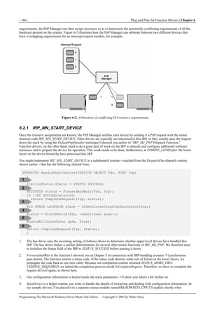
![- 164 - Plug and Play for Function Drivers | Chapter 6
Programming The Microsoft Windows Driver Model 2nd Edition Copyright © 2003 by Walter Oney
Figure 6-1. State diagram for a device.
This chapter also discusses PnP notifications, which provide a way for drivers and user-mode programs to learn
asynchronously about the arrival and departure of devices. Properly handling these notifications is important for applications
that work with devices that can be hot plugged and unplugged.
I’ve devoted a separate chapter (Chapter 11) to bus and multifunction drivers.
TIP
You can save yourself a lot of work by copying and using my GENERIC.SYS library. Instead of writing your own
elaborate dispatch function for IRP_MJ_PNP, simply delegate this IRP to GenericDispatchPnp. See the
Introduction for a table that lists the callback functions your driver supplies to perform device-specific
operations. I’ve used the same callback function names in this chapter. In addition, I’m basically using
GENERIC’s PnP handling code for all of the examples.
6.1 IRP_MJ_PNP Dispatch Function
A simplified version of the dispatch function for IRP_MJ_PNP might look like the following:
NTSTATUS DispatchPnp(PDEVICE_OBJECT fdo, PIRP Irp)
{
PIO_STACK_LOCATION stack = IoGetCurrentIrpStackLocation(Irp);
ULONG fcn = stack->MinorFunction;
static NTSTATUS (*fcntab[])(PDEVICE_OBJECT, PIRP) = {
HandleStartDevice, // IRP_MN_START_DEVICE
HandleQueryRemove, // IRP_MN_QUERY_REMOVE_DEVICE
<etc.>,
};
if (fcn >= arraysize(fcntab))
return DefaultPnpHandler(fdo, Irp);
return (*fcntab[fcn])(fdo, Irp);
}
NTSTATUS DefaultPnpHandler(PDEVICE_OBJECT fdo, PIRP Irp)
{
IoSkipCurrentIrpStackLocation(Irp);
PDEVICE_EXTENSION pdx =
(PDEVICE_EXTENSION) fdo->DeviceExtension;](https://image.slidesharecdn.com/2-programming-151105001030-lva1-app6892/85/2-programming-the-microsoft-windows-driver-model-2nd-edition-182-320.jpg)
![6.2 Starting and Stopping Your Device - 165 -
Programming The Microsoft Windows Driver Model 2nd Edition Copyright © 2003 by Walter Oney
return IoCallDriver(pdx->LowerDeviceObject, Irp);
}
1. All the parameters for the IRP, including the all-important minor function code, are in the stack location. Hence, we
obtain a pointer to the stack location by calling IoGetCurrentIrpStackLocation.
2. We expect the IRP’s minor function code to be one of those listed in Table 6‐1.
3. A method of handling the two dozen possible minor function codes is to write a subdispatch function for each one we’re
going to handle and then to define a table of pointers to those subdispatch functions. Many of the entries in the table will
be DefaultPnpHandler. Subdispatch functions such as HandleStartDevice will take pointers to a device object and an IRP
as parameters and will return an NTSTATUS code.
4. If we get a minor function code we don’t recognize, it’s probably because Microsoft defined a new one in a release of the
DDK after the DDK with which we built our driver. The right thing to do is to pass the minor function code down the
stack by calling the default handler. By the way, arraysize is a macro in one of my own header files that returns the
number of elements in an array. It’s defined as #define arraysize(p) (sizeof(p)/sizeof((p)[0])).
5. This is the operative statement in the dispatch routine, in which we index the table of subdispatch functions and call the
right one.
6. The DefaultPnpHandler routine is essentially the ForwardAndForget function I showed in connection with IPR-handling
scenario 2 in the preceding chapter. We’re passing the IRP down without a completion routine and therefore use
IoSkipCurrentIrpStackLocation to retard the IRP stack pointer in anticipation that IoCallDriver will immediately advance
it.
Using a Function Pointer Table
Using a table of function pointers to dispatch handlers for minor function codes as I’m showing you in
DispatchPnp entails some slight danger. A future version of the operating system might change the meaning of
some of the codes. That’s not a practical worry except during the beta test phase of a system, though, because
a later change would invalidate an unknown number of existing drivers. I like using a table of pointers to
subdispatch functions because having separate functions for the minor function codes seems like the right
engineering solution to me. If I were designing a C++ class library, for instance, I’d define a base class that
used virtual functions for each of the minor function codes.
Most programmers would probably place a switch statement in their DispatchPnp routine. You can simply
recompile your driver to conform to any reassignment of minor function codes. Recompilation will also
highlight—by producing compilation errors!—name changes that might signal functionality shifts. That
happened a time or two during the Microsoft Windows 98 and Windows 2000 betas, in fact. Furthermore, an
optimizing compiler should be able to use a jump table to produce slightly faster code for a switch statement
than for calls to subdispatch functions.
I think the choice between a switch statement and a table of function pointers is mostly a matter of taste, with
readability and modularity winning over efficiency in my own evaluation. You can avoid uncertainty during a
beta test by placing appropriate assertions in your code. For example, the HandleStartDevice function can
assert that stack->MinorFunction == IRP_MN_START_DEVICE. If you recompile your driver with each new beta
DDK, you’ll catch any number reassignments or name changes.
6.2 Starting and Stopping Your Device
Working with the bus driver, the PnP Manager automatically detects hardware and assigns I/O resources in Windows XP and
Windows 98/Me. Most modern devices have PnP features that allow system software to detect them automatically and to
electronically determine which I/O resources they require. In the case of legacy devices that have no electronic means of
identifying themselves to the operating system or of expressing their resource requirements, the registry database contains the
information needed for the detection and assignment operations.
NOTE
I find it hard to give an abstract definition of the term I/O resource that isn’t circular (for example, a resource
used for I/O), so I’ll give a concrete one instead. The WDM encompasses four standard I/O resource types: I/O
ports, memory registers, direct memory access (DMA) channels, and interrupt requests.
When the PnP Manager detects hardware, it consults the registry to learn which filter drivers and function drivers will manage
the hardware. As I discussed in Chapter 2, the PnP Manager loads these drivers (if necessary—one or more of them might
already be present, having been called into memory on behalf of some other hardware) and calls their AddDevice functions.
The AddDevice functions, in turn, create device objects and link them into a stack. At this point, the stage is set for the PnP
Manager, working with all of the device drivers, to assign I/O resources.
The PnP Manager initially creates a list of resource requirements for each device and allows the drivers to filter that list. I’m
going to ignore the filtering step for now because not every driver will need to participate in this step. Given a list of](https://image.slidesharecdn.com/2-programming-151105001030-lva1-app6892/85/2-programming-the-microsoft-windows-driver-model-2nd-edition-183-320.jpg)
![6.2 Starting and Stopping Your Device - 167 -
Programming The Microsoft Windows Driver Model 2nd Edition Copyright © 2003 by Walter Oney
arguments you would pass to this routine besides the address of the device object.
5. EnableAllInterfaces enables all the device interfaces that you registered in your AddDevice routine. This step allows
applications to find your device when they use SetupDiXxx functions to enumerate instances of your registered interfaces.
6. Since ForwardAndWait short-circuited the completion process for the START_DEVICE request, we need to complete the
IRP a second time. In this example, I’m using an overloaded version of CompleteRequest that doesn’t change
IoStatus.Information, in accordance with the DDK rules for handling PnP requests.
You might guess (correctly!) that the IRP_MN_START_DEVICE handler has work to do that concerns the transition from the
initial STOPPED state to the WORKING state. I can’t explain that yet because I need to first explain the ramifications of other
PnP requests on state transitions, IRP queuing, and IRP cancellation. So I’m going to concentrate for a while on the
configuration aspects of the PnP requests.
The I/O stack location’s Parameters union has a substructure named StartDevice that contains the configuration information
you pass to the StartDevice helper function. See Table 6-2.
Field Name Description
AllocatedResources Contains raw resource assignments
AllocatedResourcesTranslated Contains translated resource assignments
Table 6-2. Fields in the Parameters.StartDevice Substructure of an I/O Stack Location
Both AllocatedResources and AllocatedResourcesTranslated are instances of the same kind of data structure, called a
CM_RESOURCE_LIST. This seems like a very complicated data structure if you judge only by its declaration in WDM.H. As
used in a start device IRP, however, all that remains of the complication is a great deal of typing. The “lists” will have just one
entry, a CM_PARTIAL_RESOURCE_LIST that describes all of the I/O resources assigned to the device. You can use statements
like the following to access the two lists:
PCM_PARTIAL_RESOURCE_LIST raw, translated;
raw = &stack->Parameters.StartDevice
.AllocatedResources->List[0].PartialResourceList;
translated = &stack->Parameters.StartDevice
.AllocatedResourcesTranslated->List[0].PartialResourceList;
The only difference between the last two statements is the reference to either the AllocatedResources or
AllocatedResourcesTranslated member of the parameters structure.
The raw and translated resource lists are the logical arguments to send to the StartDevice helper function, by the way:
status = StartDevice(fdo, raw, translated);
There are two different lists of resources because I/O buses and the CPU can address the same physical hardware in different
ways. The raw resources contain numbers that are bus-relative, whereas the translated resources contain numbers that are
system-relative. Prior to the WDM, a kernel-mode driver might expect to retrieve raw resource values from the registry, the
Peripheral Component Interconnect (PCI) configuration space, or some other source, and to translate them by calling routines
such as HalTranslateBusAddress and HalGetInterruptVector. See, for example, Art Baker’s The Windows NT Device Driver
Book: A Guide for Programmers (Prentice Hall, 1997), pages 122-62. Both the retrieval and translation steps are done by the
PnP Manager now, and all a WDM driver needs to do is access the parameters of a start device IRP as I’m now describing.
What you actually do with the resource descriptions inside your StartDevice function is a subject for Chapter 7.
6.2.2 IRP_MN_STOP_DEVICE
The stop device request tells you to shut your device down so that the PnP Manager can reassign I/O resources. At the
hardware level, shutting down involves pausing or halting current activity and preventing further interrupts. At the software
level, it involves releasing the I/O resources you configured at start device time. Within the framework of the
dispatch/subdispatch architecture I’ve been illustrating, you might have a subdispatch function like this one:
NTSTATUS HandleStopDevice(PDEVICE_OBJECT fdo, PIRP Irp)
{
<complicated stuff>
StopDevice(fdo, oktouch);
Irp->IoStatus.Status = STATUS_SUCCESS;
return DefaultPnpHandler(fdo, Irp);
}](https://image.slidesharecdn.com/2-programming-151105001030-lva1-app6892/85/2-programming-the-microsoft-windows-driver-model-2nd-edition-185-320.jpg)
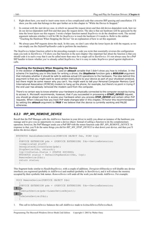
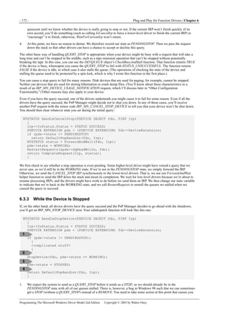
;
if (fcn != IRP_MN_REMOVE_DEVICE)
IoReleaseRemoveLock(&pdx->RemoveLock, Irp);
return status;
}
In other words, DispatchPnp locks the device, calls the subdispatch routine, and then (usually) unlocks the device afterward.
The subdispatch routine for IRP_MN_REMOVE_DEVICE has additional special logic that you also haven’t seen yet:
NTSTATUS HandleRemoveDevice(PDEVICE_OBJECT fdo, PIRP Irp)
{
Irp->IoStatus.Status = STATUS_SUCCESS;
PDEVICE_EXTENSION pdx = (PDEVICE_EXTENSION) fdo->DeviceExtension;
AbortRequests(&pdx->dqReadWrite, STATUS_DELETE_PENDING);
DeregisterAllInterfaces(pdx);
StopDevice(fdo, pdx->state == WORKING);
pdx->state = REMOVED;
NTSTATUS status = DefaultPnpHandler(pdx->LowerDeviceObject, Irp);
IoReleaseRemoveLockAndWait(&pdx->RemoveLock, Irp);
RemoveDevice(fdo);
return status;
}
1. Windows 98/Me doesn’t send the SURPRISE_REMOVAL request, so this REMOVE IRP may be the first indication you
have that the device has disappeared. Calling StopDevice allows you to release all your I/O resources in case you didn’t
get an earlier IRP that caused you to release them. Calling AbortRequests causes you to complete any queued IRPs and to
start rejecting any new IRPs.
2. We pass this request to the lower layers now that we’ve done our work.
3. The PnP dispatch routine acquired the remove lock. We now call the special function IoReleaseRemoveLockAndWait to
release that lock reference and wait until all references to the lock are released. Once you call
IoReleaseRemoveLockAndWait, any subsequent call to IoAcquireRemoveLock will elicit a STATUS_DELETE_PENDING
status to indicate that device removal is under way.
NOTE
You’ll notice that the IRP_MN_REMOVE_DEVICE handler might block while an IRP finishes. This is certainly OK
in Windows 98/Me and Windows XP, which were designed with this possibility in mind—the IRP gets sent in the
context of a system thread that’s allowed to block. Some WDM functionality (a Microsoft developer even called
it “embryonic”) is present in OEM releases of Microsoft Windows 95, but you can’t block a remove device
request there. Consequently, if your driver needs to run in Windows 95, you need to discover that fact and avoid
blocking. That discovery process is left as an exercise for you.
It bears repeating that you need to use the remove lock only for an IRP that you pass down the PnP stack. If you have the
stamina, you can read the next section to understand exactly why this conclusion is true—and note that it differs from the
conventional wisdom that I and others have been espousing for several years. If someone sends you an IRP that you handle
entirely inside your own driver, you can rely on whoever sent you the IRP to make sure your driver remains in memory until
you both complete the IRP and return from your dispatch routine. If you send an IRP to someone outside your PnP stack, you’ll
use other means (such as a referenced file or device object) to keep the target driver in memory until it both completes the IRP
and returns from its dispatch routine.](https://image.slidesharecdn.com/2-programming-151105001030-lva1-app6892/85/2-programming-the-microsoft-windows-driver-model-2nd-edition-193-320.jpg)
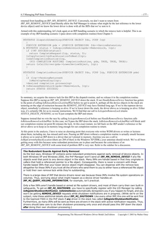
![6.4 Other Configuration Functionality - 181 -
Programming The Microsoft Windows Driver Model 2nd Edition Copyright © 2003 by Walter Oney
NOTE
If your device might be removed in such a way that an outstanding request simply hangs, you should also have
some sort of watchdog timer running that will let you kill the IRP after a specified period of time. See the
“Watchdog Timers“ section in Chapter 14.
Sometimes we need to undo the effect of a previous call to AbortRequest. AllowRequests lets us do that:
VOID NTAPI AllowRequests(PDEVQUEUE pdq)
{
pdq->abortstatus = (NTSTATUS) 0;
}
6.4 Other Configuration Functionality
Up to this point, I’ve talked about the important concepts you need to know to write a hardware device driver. I’ll discuss two
less important minor function codes—IRP_MN_FILTER_RESOURCE_REQUIREMENTS and IRP_MN_DEVICE_
USAGE_NOTIFICATION—that you might need to process in a practical driver. Finally I’ll mention how you can register to
receive notifications about PnP events that affect devices other than your own.
6.4.1 Filtering Resource Requirements
Sometimes the PnP Manager is misinformed about the resource requirements of your driver. This can occur because of
hardware and firmware bugs, mistakes in the INF file for a legacy device, or other reasons. The system provides an escape
valve in the form of the IRP_MN_FILTER_RESOURCE_REQUIREMENTS request, which affords you a chance to examine
and possibly alter the list of resources before the PnP Manager embarks on the arbitration and assignment process that
culminates in your receiving a start device IRP.
When you receive a filter request, the FilterResourceRequirements substructure of the Parameters union in your stack location
points to an IO_RESOURCE_REQUIREMENTS_LIST data structure that lists the resource requirements for your device. In
addition, if any of the drivers above you have processed the IRP and modified the resource requirements, the
IoStatus.Information field of the IRP will point to a second IO_RESOURCE_REQUIREMENTS_LIST, which is the one from
which you should work. Your overall strategy will be as follows: If you want to add a resource to the current list of
requirements, you do so in your dispatch routine. Then you pass the IRP down the stack synchronously—that is, by using the
ForwardAndWait method you use with a start device request. When you regain control, you can modify or delete any of the
resource descriptions that appear in the list.
Here’s a brief and not very useful example that illustrates the mechanics of the filtering process:
NTSTATUS HandleFilterResources(PDEVICE_OBJECT fdo, PIRP Irp)
{
PDEVICE_EXTENSION pdx = (PDEVICE_EXTENSION) fdo->DeviceExtension;
PIO_STACK_LOCATION stack = IoGetCurrentIrpStackLocation(Irp);
PIO_RESOURCE_REQUIREMENTS_LIST original = stack->Parameters
.FilterResourceRequirements.IoResourceRequirementList;
PIO_RESOURCE_REQUIREMENTS_LIST filtered =
(PIO_RESOURCE_REQUIREMENTS_LIST) Irp->IoStatus.Information;
PIO_RESOURCE_REQUIREMENTS_LIST source = filtered ? filtered : original;
if (source->AlternativeLists != 1)
return DefaultPnpHandler(fdo, Irp);
ULONG sizelist = source->ListSize;
PIO_RESOURCE_REQUIREMENTS_LIST newlist =
(PIO_RESOURCE_REQUIREMENTS_LIST) ExAllocatePool(PagedPool,
sizelist + sizeof(IO_RESOURCE_DESCRIPTOR));
if (!newlist)
return DefaultPnpHandler(fdo, Irp);
RtlCopyMemory(newlist, source, sizelist);
newlist->ListSize += sizeof(IO_RESOURCE_DESCRIPTOR);
PIO_RESOURCE_DESCRIPTOR resource =
&newlist->List[0].Descriptors[newlist->List[0].Count++];
RtlZeroMemory(resource, sizeof(IO_RESOURCE_DESCRIPTOR));](https://image.slidesharecdn.com/2-programming-151105001030-lva1-app6892/85/2-programming-the-microsoft-windows-driver-model-2nd-edition-199-320.jpg)
![- 182 - Plug and Play for Function Drivers | Chapter 6
Programming The Microsoft Windows Driver Model 2nd Edition Copyright © 2003 by Walter Oney
resource->Type = CmResourceTypeDevicePrivate;
resource->ShareDisposition = CmResourceShareDeviceExclusive;
resource->u.DevicePrivate.Data[0] = 42;
Irp->IoStatus.Information = (ULONG_PTR) newlist;
if (filtered && filtered != original)
ExFreePool(filtered);
NTSTATUS status = ForwardAndWait(fdo, Irp);
if (NT_SUCCESS(status))
{
// stuff
}
Irp->IoStatus.Status = status;
IoCompleteRequest(Irp, IO_NO_INCREMENT);
return status;
}
1. The parameters for this request include a list of I/O resource requirements. These are derived from the device’s
configuration space, the registry, or wherever the bus driver happens to find them.
2. Higher-level drivers might have already filtered the resources by adding requirements to the original list. If so, they set
the IoStatus.Information field to point to the expanded requirements list structure.
3. If there’s no filtered list, we’ll extend the original list. If there’s a filtered list, we’ll extend that.
4. Theoretically, several alternative lists of requirements could exist, but dealing with that situation is beyond the scope of
this simple example.
5. We need to add any resources before we pass the request down the stack. First we allocate a new requirements list and
copy the old requirements into it.
6. Taking care to preserve the preexisting order of the descriptors, we add our own resource description. In this example,
we’re adding a resource that’s private to the driver.
7. We store the address of the expanded list of requirements in the IRP’s IoStatus.Information field, which is where
lower-level drivers and the PnP system will be looking for it. If we just extended an already filtered list, we need to
release the memory occupied by the old list.
8. We pass the request down using the same ForwardAndWait helper function that we used for IRP_MN_START_DEVICE.
If we weren’t going to modify any resource descriptors on the IRP’s way back up the stack, we could just call
DefaultPnpHandler here and propagate the returned status.
9. When we complete this IRP, whether we indicate success or failure, we must take care not to modify the Information
field of the I/O status block: it might hold a pointer to a resource requirements list that some driver—maybe even
ours!—installed on the way down. The PnP Manager will release the memory occupied by that structure when it’s no
longer needed.
6.4.2 Device Usage Notifications
Disk drivers (and the drivers for disk controllers) in particular sometimes need to know extrinsic facts about how they’re being
used by the operating system, and the IRP_MN_DEVICE_USAGE_NOTIFICATION request provides a means to gain that
knowledge. The I/O stack location for the IRP contains two parameters in the Parameters.UsageNotification substructure. See
Table 6-4. The InPath value (a Boolean) indicates whether the device is in the device path required to support that usage, and
the Type value indicates one of several possible special usages.
Parameter Description
InPath TRUE if device is in the path of the Type usage; FALSE if not
Type Type of usage to which the IRP applies
Table 6-4. Fields in the Parameters.UsageNotification Substructure of an I/O Stack Location
In the subdispatch routine for the notification, you should have a switch statement (or other logic) that differentiates among the
notifications you know about. In most cases, you’ll pass the IRP down the stack. Consequently, a skeleton for the subdispatch
function is as follows:
NTSTATUS HandleUsageNotification(PDEVICE_OBJECT fdo, PIRP Irp)
{
PDEVICE_EXTENSION pdx = (PDEVICE_EXTENSION) fdo->DeviceExtension;](https://image.slidesharecdn.com/2-programming-151105001030-lva1-app6892/85/2-programming-the-microsoft-windows-driver-model-2nd-edition-200-320.jpg)
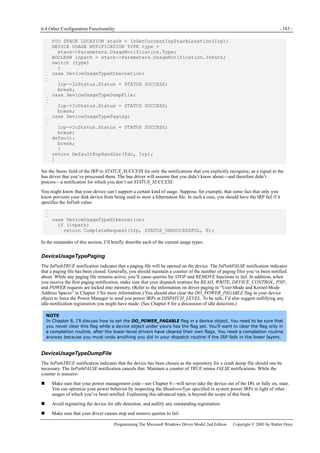
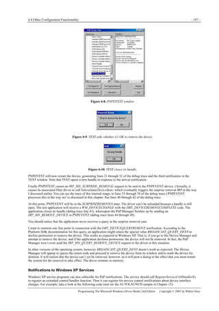
![- 190 - Plug and Play for Function Drivers | Chapter 6
Programming The Microsoft Windows Driver Model 2nd Edition Copyright © 2003 by Walter Oney
This doesn’t have any more information than the header structure itself—just a different typedef name.
One way to use these notifications is to implement a filter driver for an entire class of device interfaces. (There is a standard
way to implement filter drivers, either for a single driver or for a class of devices, based on setting entries in the registry. I’ll
discuss that subject in Chapter 16. Here I’m talking about filtering all devices that register a particular interface, for which
there’s no other mechanism.) In your driver’s DriverEntry routine, you register for PnP notifications about one or more
interface GUIDs. When you receive the arrival notification, you use IoGetDeviceObjectPointer to open a file object and then
register for target device notifications about the associated device. You also get a device object pointer from
IoGetDeviceObjectPointer, and you can send IRPs to that device by calling IoCallDriver. Be on the lookout for the
GUID_TARGET_DEVICE_QUERY_REMOVE notification because you have to dereference the file object before the removal
can continue.
The PNPMON Sample
The PNPMON sample illustrates how to register for and process PnP notifications in kernel mode. To give you
something you can run on your computer and actually see working, I designed PNPMON to simply pass
notifications back to a user-mode application (named TEST—what else?). This is pretty silly in that a user-mode
application can get these notifications on its own by calling RegisterDeviceNotification.
PNPMON is different from the other driver samples in this book. It’s intended to be dynamically loaded as a
helper for a user-mode application. The other drivers we look at are intended to manage hardware, real or
imagined. The user-mode application uses service manager API calls to load PNPMON, which creates exactly
one device object in its DriverEntry routine so that the application can use DeviceIoControl to get things done
in kernel mode. When the application exits, it closes its handle and calls the service manager to terminate the
driver.
PNPMON also includes a Windows 98/Me virtual device driver (VxD) that the test application can dynamically
load. It’s possible to dynamically load a WDM driver in Windows 98/Me by using an undocumented function
(_NtKernLoadDriver, if you care), but there’s no way to unload a driver that you’ve loaded in this way. You don’t
need to resort to undocumented functions, though, because VxDs can call most of the WDM support routines
directly by means of the WDMVXD import library in the Windows 98 DDK. (This library is missing from the
Windows Me portion of the Windows XP DDK.) Just about the only extra things you need to do in your VxD
project are include WDM.H ahead of the VxD header files and add WDMVXD.CLB to the list of inputs to the linker.
So PNPMON.VXD simply registers for PnP notifications as if it were a WDM driver and supports the same IOCTL
interface that PNPMON.SYS supports.
Custom Notifications
I’ll close this section by explaining how a WDM driver can generate custom PnP notifications. To signal a custom PnP event,
create an instance of the custom notification structure and call one of IoReportTargetDeviceChange or
IoReportTargetDeviceChangeAsynchronous. The asynchronous flavor returns immediately. The synchronous flavor waits—a
long time, in my experience—until the notification has been sent. The notification structure has this declaration:
typedef struct _TARGET_DEVICE_CUSTOM_NOTIFICATION {
USHORT Version;
USHORT Size;
GUID Event;
PFILE_OBJECT FileObject;
LONG NameBufferOffset;
UCHAR CustomDataBuffer[1];
} TARGET_DEVICE_CUSTOM_NOTIFICATION, *PTARGET_DEVICE_CUSTOM_NOTIFICATION;
Event is the custom GUID you’ve defined for the notification. FileObject is NULL—the PnP Manager will be sending
notifications to drivers who opened file objects for the same PDO as you specify in the IoReportXxx call. CustomDataBuffer
contains whatever binary data you elect followed by Unicode string data. NameBufferOffset is -1 if you don’t have any string
data; otherwise, it’s the length of the binary data that precedes the strings. You can tell how big the total data payload is by
subtracting the field offset of CustomDataBuffer from the Size value.
Here’s how PNPEVENT generates a custom notification when you press the Send Event button in the associated test dialog:
struct _RANDOM_NOTIFICATION : public _TARGET_DEVICE_CUSTOM_NOTIFICATION {
WCHAR text[14];
};
_RANDOM_NOTIFICATION notify;
notify.Version = 1;
notify.Size = sizeof(notify);
notify.Event = GUID_PNPEVENT_EVENT;
notify.FileObject = NULL;
notify.NameBufferOffset = FIELD_OFFSET(RANDOM_NOTIFICATION, text)](https://image.slidesharecdn.com/2-programming-151105001030-lva1-app6892/85/2-programming-the-microsoft-windows-driver-model-2nd-edition-208-320.jpg)

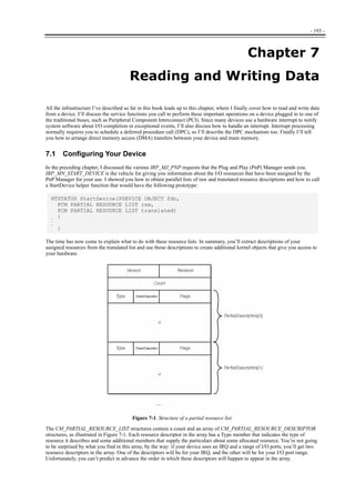
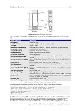
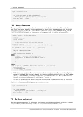
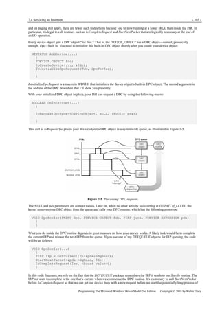
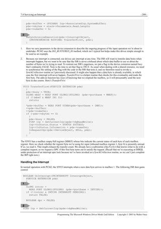
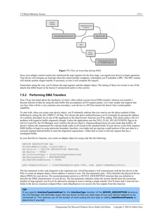
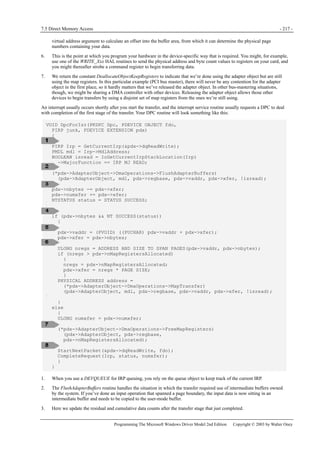
![- 218 - Reading and Writing Data | Chapter 7
Programming The Microsoft Windows Driver Model 2nd Edition Copyright © 2003 by Walter Oney
4. At this point, you determine whether the current stage of the transfer completed successfully or with an error. You might,
for example, read a status port or inspect the results of a similar operation performed by your interrupt routine. In this
example, I set the status variable to STATUS_SUCCESS with the expectation that you’d change it if you discovered an
error here.
5. If the transfer hasn’t finished yet, you need to program another stage. The first step in this process is to calculate the
virtual address of the next portion of the user-mode buffer. Bear in mind that this calculation is merely working with a
number—we’re not actually trying to access memory by using this virtual address. Accessing the memory would be a bad
idea, of course, because we’re currently executing in an arbitrary thread context.
6. The next few statements are almost identical to the ones we performed in the first stage for StartIo and AdapterControl.
The end result will be a logical address that can be programmed into your device. It might or might not correspond to a
physical address as understood by the CPU. One slight wrinkle is that we’re constrained to use only as many map
registers as were allocated by the adapter control routine; StartIo saved that number in the nMapRegistersAllocated field
of the device extension.
7. If the entire transfer is now complete, we need to release the map registers we’ve been using.
8. The remaining few statements in the DPC routine handle the mechanics of completing the IRP that got us here in the first
place.
Transfers Using Scatter/Gather Lists
If your hardware has scatter/gather support, the system has a much easier time doing DMA transfers to and from your device.
The scatter/gather capability permits the device to perform a transfer involving pages that aren’t contiguous in physical
memory.
Your StartDevice routine creates its adapter object in just about the same way I’ve already discussed, except (of course) that
you’ll set the ScatterGather flag to TRUE.
The traditional method—that is, the method you would have used in previous versions of Windows NT—to program a DMA
transfer involving scatter/gather functionality is practically identical to the packet-based example considered in the section on
Performing DMA Transfers. The only difference is that instead of making one call to MapTransfer for each stage of the transfer,
you need to make multiple calls. Each call gives you the information you need for a single element in a scatter/gather list that
contains a physical address and length. When you’re done with the loop, you can send the scatter/gather list to your device by
using some device-specific method, and you can then initiate the transfer.
I’m going to make some assumptions about the framework into which you’ll fit the construction of a scatter/gather list. First,
I’ll assume that you’ve defined a manifest constant named MAXSG that represents the maximum number of scatter/gather list
elements your device can handle. To make life as simple as possible, I’m also going to assume that you can just use the
SCATTER_GATHER_LIST structure defined in WDM.H to construct the list:
typedef struct _SCATTER_GATHER_ELEMENT {
PHYSICAL_ADDRESS Address;
ULONG Length;
ULONG_PTR Reserved;
} SCATTER_GATHER_ELEMENT, *PSCATTER_GATHER_ELEMENT;
typedef struct _SCATTER_GATHER_LIST {
ULONG NumberOfElements;
ULONG_PTR Reserved;
SCATTER_GATHER_ELEMENT Elements[];
} SCATTER_GATHER_LIST, *PSCATTER_GATHER_LIST;
Finally, I’m going to suppose that you can simply allocate a maximum-size scatter/gather list in your AddDevice function and
leave it lying around for use whenever you need it:
pdx->sglist = (PSCATTER_GATHER_LIST)
ExAllocatePool(NonPagedPool, sizeof(SCATTER_GATHER_LIST) +
MAXSG * sizeof(SCATTER_GATHER_ELEMENT));
With this infrastructure in place, your AdapterControl procedure will look like this:
IO_ALLOCATION_ACTION AdapterControl(PDEVICE_OBJECT fdo,
PIRP junk, PVOID regbase, PDEVICE_EXTENSION pdx)
{
PIRP Irp = GetCurrentIrp(&pdx->dqReadWrite);
PMDL mdl = Irp->MdlAddress;
BOOLEAN isread = IoGetCurrentIrpStackLocation(Irp)](https://image.slidesharecdn.com/2-programming-151105001030-lva1-app6892/85/2-programming-the-microsoft-windows-driver-model-2nd-edition-236-320.jpg)
![7.5 Direct Memory Access - 219 -
Programming The Microsoft Windows Driver Model 2nd Edition Copyright © 2003 by Walter Oney
->MajorFunction == IRP_MJ_READ;
pdx->regbase = regbase;
KeFlushIoBuffers(mdl, isread, TRUE);
PSCATTER_GATHER_LIST sglist = pdx->sglist;
ULONG xfer = pdx->xfer;
PVOID vaddr = pdx->vaddr;
pdx->xfer = 0;
ULONG isg = 0;
while (xfer && isg < MAXSG)
{
ULONG elen = xfer;
sglist->Elements[isg].Address =
(*pdx->AdapterObject->DmaOperations->MapTransfer)
(pdx->AdapterObject, mdl, regbase, pdx->vaddr, &elen, !isread);
sglist->Elements[isg].Length = elen;
xfer -= elen;
pdx->xfer += elen;
vaddr = (PVOID) ((PUCHAR) vaddr + elen);
++isg;
}
sglist->NumberOfElements = isg;
return DeallocateObjectKeepRegisters;
}
1. See the earlier discussion of how to get a pointer to the correct IRP in an adapter control procedure.
2. We previously (in StartIo) calculated pdx->xfer based on the allowable number of map registers. We’re going to try to
transfer that much data now, but the allowable number of scatter/gather elements might further limit the amount we can
transfer during this stage. During the following loop, xfer will be the number of bytes that we haven’t yet mapped, and
we’ll recalculate pdx->xfer as we go.
3. Here’s the loop I promised you, where we call MapTransfer to construct scatter/gather elements. We’ll continue the loop
until we’ve mapped the entire stage of this transfer or until we run out of scatter/gather elements, whichever happens
first.
4. When we call MapTransfer for a scatter/gather device, it will modify the length argument (elen) to indicate how much of
the MDL starting at the given virtual address (vaddr) is physically contiguous and can therefore be mapped by a single
scatter/gather list element. It will also return the physical address of the beginning of the contiguous region.
5. Here’s where we update the variables that describe the current stage of the transfer. When we leave the loop, xfer will be
down to 0 (or else we’ll have run out of scatter/gather elements), pdx->xfer will be up to the total of all the elements we
were able to map, and vaddr will be up to the byte after the last one we mapped. We don’t update the pdx->vaddr field in
the device extension—we’re doing that in our DPC routine. Just another one of those pesky details….
6. Here’s where we increment the scatter/gather element index to reflect the fact that we’ve just used one up.
7. At this point, we have isg scatter/gather elements that we should program into our device in whatever
hardware-dependent way is appropriate. Then we should start the device working on the request.
8. Returning DeallocateObjectKeepRegisters is appropriate for a bus-mastering device. You can theoretically have a
nonmaster device with scatter/gather capability, and it would return KeepObject instead.
Your device now performs its DMA transfer and, presumably, interrupts to signal completion. Your ISR requests a DPC, and
your DPC routine initiates the next stage in the operation. The DPC routine will perform a MapTransfer loop like the one I just
showed you as part of that initiation process. I’ll leave the details of that code as an exercise for you.
Using GetScatterGatherList
Windows 2000 and Windows XP provide a shortcut to avoid the relatively cumbersome loop of calls to MapTransfer in the
common case in which you can accomplish the entire transfer by using either no map registers or no more than the maximum
number of map registers returned by IoGetDmaAdapter. The shortcut, which is illustrated in the SCATGATH sample in the
companion content, involves calling the GetScatterGatherList routine instead of AllocateAdapterChannel. Your StartIo routine](https://image.slidesharecdn.com/2-programming-151105001030-lva1-app6892/85/2-programming-the-microsoft-windows-driver-model-2nd-edition-237-320.jpg)
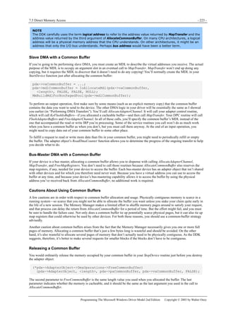

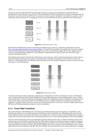
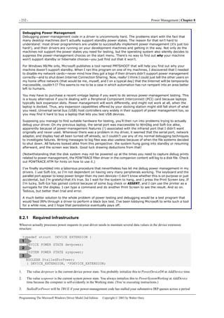
![8.2 Managing Power Transitions - 235 -
Programming The Microsoft Windows Driver Model 2nd Edition Copyright © 2003 by Walter Oney
work item (see Chapter 14) and return without destroying the state machine. The work-item callback routine then
reinvokes the state machine at PASSIVE_LEVEL to finish up.
DestroyContext is the last action performed by the state machine for any given power IRP. It releases the context structure
that the machinery has been using to keep track of state information.
I want you to notice what the net result of all of this motion has been: we have requested a device power IRP. I don’t want to
negatively characterize the kernel power-management architecture because I surely lack encyclopedic knowledge of all the
constituencies it serves and all the problems it solves. But all this motion does seem a trifle complex given the net result.
Mapping the System State to a Device State
Our obligation as power policy owner for a device is to originate a device power IRP, either a set or a query, with an
appropriate device power state. I broke this into two steps: SelectDState and SendDeviceIrp. I’ll discuss the first of these steps
now.
In general, we always want to put our device into the lowest power state that’s consistent with current device activity, with our
own wake-up feature (if any), with device capabilities, and with the impending state of the system. These factors can interplay
in a relatively complex way. To explain them fully, I need to digress briefly and talk about a PnP IRP that I avoided discussing
in Chapter 6: IRP_MN_QUERY_CAPABILITIES.
The PnP Manager sends a capabilities query shortly after starting your device and perhaps at other times. The parameter for the
request is a DEVICE_CAPABILITIES structure that contains several fields relevant to power management. Since this is the
only time in this book I’m going to discuss this structure, I’m showing you the entire declaration:
typedef struct _DEVICE_CAPABILITIES {
USHORT Size;
USHORT Version;
ULONG DeviceD1:1;
ULONG DeviceD2:1;
ULONG LockSupported:1;
ULONG EjectSupported:1;
ULONG Removable:1;
ULONG DockDevice:1;
ULONG UniqueID:1;
ULONG SilentInstall:1;
ULONG RawDeviceOK:1;
ULONG SurpriseRemovalOK:1;
ULONG WakeFromD0:1;
ULONG WakeFromD1:1;
ULONG WakeFromD2:1;
ULONG WakeFromD3:1;
ULONG HardwareDisabled:1;
ULONG NonDynamic:1;
ULONG Reserved:16;
ULONG Address;
ULONG UINumber;
DEVICE_POWER_STATE DeviceState[PowerSystemMaximum];
SYSTEM_POWER_STATE SystemWake;
DEVICE_POWER_STATE DeviceWake;
ULONG D1Latency;
ULONG D2Latency;
ULONG D3Latency;
} DEVICE_CAPABILITIES, *PDEVICE_CAPABILITIES;
Table 8-4 describes the fields in this structure that relate to power management.](https://image.slidesharecdn.com/2-programming-151105001030-lva1-app6892/85/2-programming-the-microsoft-windows-driver-model-2nd-edition-253-320.jpg)
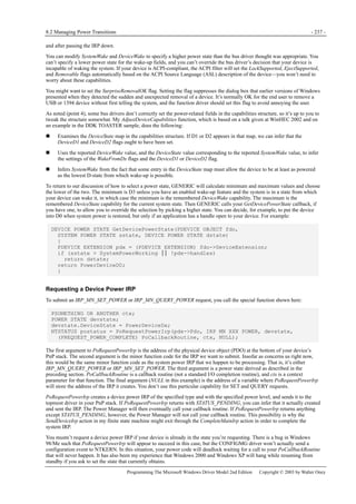
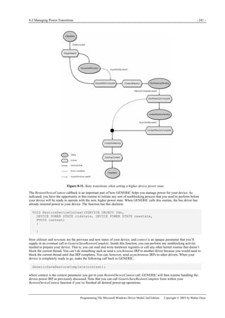
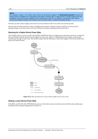
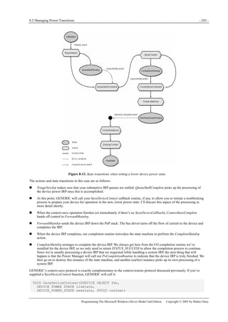
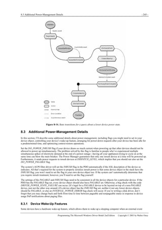
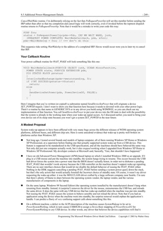
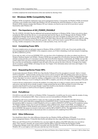

![- 255 -
Chapter 9
9 I/O Control Operations
If you look at the various types of requests that come to a device, most of them involve reading or writing data. On occasion,
however, an application needs to communicate “out of band” with the driver. For most types of device, the application can use
the standard MicrosoftWin32 API function DeviceIoControl. On the driver side, an application’s call to DeviceIoControl turns
into an I/O request packet (IRP) with the major function code IRP_MJ_DEVICE_CONTROL.
I’ll discuss the user-mode and kernel-mode sides of DeviceIoControl in this chapter. With several specific types of device,
however, an application isn’t supposed to (or can’t) use DeviceIoControl to talk to a driver. See Table 9-1.
Driver Type Alternative to DeviceIoControl
Human Interface Device (HID) minidriver (see
Chapter 13)
HidD_GetFeature, HidD_SetFeature
SCSI miniport driver IOCTL_SCSI_PASS_THROUGH
Network Driver Interface Specification (NDIS)
miniport driver
WMI request using custom GUID. You’re on your own for Win98
Gold, where WMI doesn’t work.
SmartCard reader driver (Interface Device
[IFD] Handler in PC/SC terms)
ScardControl
Table 9-1. Alternatives to DeviceIoControl for Certain Types of Driver
There is also a special problem associated with using DeviceIoControl to communicate with a filter driver. I’ll discuss that
problem and its solution in Chapter 16.
9.1 The DeviceIoControl API
The user-mode DeviceIoControl API has the following prototype:
result = DeviceIoControl(Handle, Code, InputData, InputLength,
OutputData, OutputLength, &Feedback, &Overlapped);
Handle (HANDLE) is an open handle open to the device. You obtain this handle by calling CreateFile in the following manner:
Handle = CreateFile(".IOCTL", GENERIC_READ │ GENERIC_WRITE,
0, NULL, OPEN_EXISTING, flags, NULL);
if (Handle == INVALID_HANDLE_VALUE)
<error>
CloseHandle(Handle);
The flags argument to CreateFile is either FILE_FLAG_OVERLAPPED or 0 to indicate whether you’ll be performing
asynchronous operations with this file handle. While you have the handle open, you can make calls to ReadFile, WriteFile, or
DeviceIoControl. When you’re done accessing the device, you should explicitly close the handle by calling CloseHandle. Bear
in mind, though, that the operating system automatically closes any handles that are left open when your process terminates.
The Code (DWORD) argument to DeviceIoControl is a control code that indicates the control operation you want to perform.
I’ll discuss how you define these codes a bit further on (in “Defining I/O Control Codes”). The InputData (PVOID) and
InputLength (DWORD) arguments describe a data area that you’re sending to the device driver. (That is, this data is input from
the perspective of the driver.) The OutputData (PVOID) and OutputLength (DWORD) arguments describe a data area that the
driver can completely or partially fill with information that it wants to send back to you. (That is, this data is output from the
perspective of the driver.) The driver will update the Feedback variable (a DWORD) to indicate how many bytes of output data
it gave you back. Figure 9-1 illustrates the relationship of these buffers with the application and the driver. The Overlapped
(OVERLAPPED) structure is used to help control an asynchronous operation, which is the subject of the next section. If you
specified FILE_FLAG_OVERLAPPED in the call to CreateFile, you must specify the OVERLAPPED structure pointer. If you
didn’t specify FILE_FLAG_OVERLAPPED, you might as well supply NULL for this last argument because the system is
going to ignore it anyway.](https://image.slidesharecdn.com/2-programming-151105001030-lva1-app6892/85/2-programming-the-microsoft-windows-driver-model-2nd-edition-273-320.jpg)
![9.1 The DeviceIoControl API - 257 -
Programming The Microsoft Windows Driver Model 2nd Edition Copyright © 2003 by Walter Oney
}
CloseHandle(Overlapped.hEvent);
if (code != 0)
<error>
Two major differences exist between this asynchronous example and the earlier synchronous example. First, we specify the
FILE_FLAG_OVERLAPPED flag in the call to CreateFile. Second, the call to DeviceIoControl specifies the address of an
OVERLAPPED structure, within which we’ve initialized the hEvent event handle to describe a manual reset event. (For more
information about events and thread synchronization in general, see Jeffrey Richter’s Programming Applications for Microsoft
Windows, Fourth Edition [Microsoft Press, 1999].)
The asynchronous call to DeviceIoControl will have one of three results. First, it might return TRUE, meaning that the device
driver’s dispatch routine was able to complete the request right away. Second, it might return FALSE, and GetLastError might
retrieve the special error code ERROR_IO_PENDING. This result indicates that the driver’s dispatch routine returned
STATUS_PENDING and will complete the control operation later. Note that ERROR_IO_PENDING isn’t really an error—it’s
one of the two ways in which the system indicates that everything is proceeding normally. The third possible result from the
asynchronous call to DeviceIoControl is a FALSE return value coupled with a GetLastError value other than
ERROR_IO_PENDING. Such a result would be a real error.
At the point at which the application needs the result of the control operation, it calls one of the Win32 synchronization
primitives—GetOverlappedResult, WaitForSingleObject, or the like. GetOverlappedResult, the synchronization primitive I use
in this example, is especially convenient because it also retrieves the bytes-transferred feedback value and sets the
GetLastError result to indicate the result of the I/O operation. Although you can call WaitForSingleObject or a related
API—passing the Overlapped.hEvent event handle as an argument—you won’t be able to learn the results of the
DeviceIoControl operation; you’ll just learn that the operation has finished.
9.1.2 Defining I/O Control Codes
The Code argument to DeviceIoControl is a 32-bit numeric constant that you define using the CTL_CODE preprocessor macro
that’s part of both the DDK and the Platform SDK. Figure 9-2 illustrates the way in which the operating system partitions one
of these 32-bit codes into subfields.
Figure 9-2. Fields in an I/O control code.
The fields have the following interpretation:
The device type (16 bits, first argument to CTL_CODE) indicates the type of device that implements this control
operation. You should use the same value (for example, FILE_DEVICE_UNKNOWN) that you use in the driver when you
call IoCreateDevice. (File system device type codes cause the I/O Manager to use a different major function code for the
IRP it sends you.)
The access code (2 bits, fourth argument to CTL_CODE) indicates the access rights an application needs to its device
handle to issue this control operation.
The function code (12 bits, second argument to CTL_CODE) indicates precisely which control operation this code
describes. Microsoft reserves the first half of the range of this field—that is, values 0 through 2047—for standard control
operations. You and I therefore assign values in the range 2048 through 4095. The main purpose of this convention is to
allow you to define private control operations for standard devices.
The buffering method (2 bits, third argument to CTL_CODE) indicates how the I/O Manager is to handle the input and
output buffers supplied by the application. I’ll have a great deal to say about this field in the next section, when I describe
how to implement IRP_MJ_DEVICE_CONTROL in a driver.
I want to clarify one point of possible confusion. When you create your driver, you’re free to design a series of IOCTL
operations that applications can use in talking to your driver. Although some other driver author might craft a set of IOCTL
operations that uses exactly the same numeric values for control codes, the system will never be confused by the overlap
because IOCTL codes are interpreted by only the driver to which they’re addressed. Mind you, if you opened a handle to a
device belonging to that hypothetical other driver and then tried to send what you thought was one of your own IOCTLs to it,
confusion would definitely ensue.
The access code in an I/O control code gives you the ability to divide the world of users into four parts, based on a
security descriptor you attach to your device object:
Users to whom the security descriptor denies all access can’t open a handle, so they can’t issue any IOCTLs at all.
Users whom the security descriptor allows to open handles for reading but not writing can issue IOCTLs whose function
code specifies FILE_READ_ACCESS or FILE_ANY_ACCESS, but not those whose code specifies
FILE_WRITE_ACCESS.](https://image.slidesharecdn.com/2-programming-151105001030-lva1-app6892/85/2-programming-the-microsoft-windows-driver-model-2nd-edition-275-320.jpg)
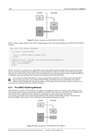
![- 264 - I/O Control Operations | Chapter 9
Programming The Microsoft Windows Driver Model 2nd Edition Copyright © 2003 by Walter Oney
DriverObject->MajorFunction[IRP_MJ_DEVICE_CONTROL] =
DispatchControl;
DriverObject->MajorFunction[IRP_MJ_INTERNAL_DEVICE_CONTROL] =
DispatchControl;
}
NTSTATUS DispatchControl(...)
{
switch (code)
{
case IOCTL_GET_VERSION:
case IOCTL_INTERNAL_GET_SECRET:
// <== exposed for user-mode calls
}
}
If an application is able to somehow determine the numeric value of IOCTL_INTERNAL_GET_SECRET, it can issue a regular
DeviceIoControl call and bypass the intended security on that function.
9.5 Notifying Applications of Interesting Events
One extremely important use of IOCTL operations is to give a WDM driver a way to notify an application that an interesting
event (however you define “interesting,” that is) has occurred. To motivate this discussion, suppose you had an application that
needed to work closely with your driver in such a way that whenever a certain kind of hardware event occurred your driver
would alert the application so that it could take some sort of user-visible action. For example, a button press on an instrument
might trigger an application to begin collecting and displaying data. Whereas Windows 98/Me provides a couple of ways for a
driver to signal an application in this kind of situation—namely, asynchronous procedure calls or posted window
messages—those methods don’t work in Windows XP because the operating system lacks (or doesn’t expose) the necessary
infrastructure to make them work.
A WDM driver can notify an application about an interesting event in two ways:
The application can create an event that it shares with the driver. An application thread waits on the event, and the driver
sets the event when something interesting happens.
The application can issue a DeviceIoControl that the driver pends by returning STATUS_PENDING. The driver completes
the IRP when something interesting happens.
In either case, the application typically dedicates a thread to the task of waiting for the notification. That is, when you’re
sharing an event, you have a thread that spends most of its life asleep on a call to WaitForSingleObject. When you use a
pending IOCTL, you have a thread that spends most of its life waiting for DeviceIoControl to return. This thread doesn’t do
anything else except, perhaps, post a window message to a user interface thread to make something happen that will be visible
to the end user.
How to Organize Your Notification Thread
When using either notification method, you can avoid some “plumbing” problems by not having the notification
thread block simply on the event or the IOCTL, as the case may be. Instead, proceed as follows: First define a
“kill” event that your main application thread will set when it’s time for the notification thread to exit.
If you’re using the shared event scheme for notification, call WaitForMultipleObjects to wait for either the kill
event or the event you’re sharing with the driver.
If you’re using the pending IOCTL scheme, make asynchronous calls to DeviceIoControl. Instead of calling
GetOverlappedResult to block, call WaitForMultipleObjects to wait for either the kill event or the event
associated with the OVERLAPPED structure. If the return code indicates that the DeviceIoControl operation has
finished, you make a nonblocking call to GetOverlappedResult to get the return code and bytes-transferred
values. If the return code indicates that the kill event has been signaled, you call CancelIo to knock down the
DeviceIoControl, and you then exit from the thread procedure. Leave out the call to CancelIo if your application
has to run in Windows 98 Second Edition.
These two methods of solving the notification problem have the relative strengths and weaknesses shown in Table 9-3.
Notwithstanding that it appears superficially as though the pending IOCTL method has all sorts of advantages over the shared
event method, I recommend you use the shared event method because of the complexity of the race conditions you must
handle with the pending IOCTL method.](https://image.slidesharecdn.com/2-programming-151105001030-lva1-app6892/85/2-programming-the-microsoft-windows-driver-model-2nd-edition-282-320.jpg)
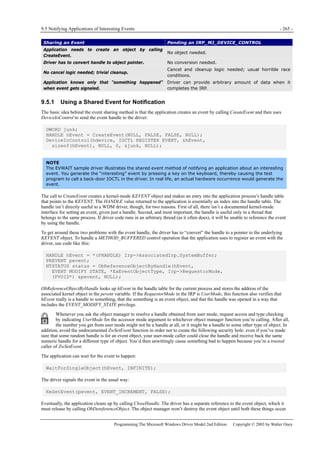
![9.5 Notifying Applications of Interesting Events - 267 -
Programming The Microsoft Windows Driver Model 2nd Edition Copyright © 2003 by Walter Oney
NOTE
You can easily generalize the scheme I’m describing to permit an application to have an IRP of each type
outstanding for each open handle. Instead of putting the current IRP pointers in your device extension, put
them instead into a structure that you associate with the FILE_OBJECT that corresponds to the handle. You’ll
get a pointer to this FILE_OBJECT in the I/O stack location for IRP_MJ_CREATE, IRP_MJ_CLOSE, and, in fact, all
other IRPs generated for the file handle. You can use either the FsContext or FsContext2 field of the file object
for any purpose you choose.
Later, when whatever event the application is waiting for occurs, we execute code like this:
PIRP nfyirp = UncacheControlRequest(pdx, &pdx->NotifyIrp);if (nfyirp)
{
<do something>
CompleteRequest(nfyirp, STATUS_SUCCESS, <info value>);
}
This logic retrieves the address of the pending IOCTL_WAIT_NOTIFY request, does something to provide data back to the
application, and then completes the pending I/O request packet.
How the Helper Routines Work
I hid a wealth of complications inside the CacheControlRequest and UncacheControlRequest functions. These two functions
provide a thread-safe and multiprocessor-safe mechanism for keeping track of asynchronous IOCTL requests. They use a
variation on the techniques we’ve discussed elsewhere in the book for safely queuing and dequeuing IRPs at times when
someone else might be flitting about trying to cancel the IRP. I actually packaged these routines in GENERIC.SYS, and the
NOTIFY sample in the companion content shows how to call them. Here’s how those functions work (but note that the
GENERIC.SYS versions have ‘Generic’ in their names):
typedef struct _DEVICE_EXTENSION {
KSPIN_LOCK IoctlListLock;
LIST_ENTRY PendingIoctlList;
} DEVICE_EXTENSION, *PDEVICE_EXTENSION;
NTSTATUS CacheControlRequest(PDEVICE_EXTENSION pdx, PIRP Irp, PIRP* pIrp)
{
KIRQL oldirql;
KeAcquireSpinLock(&pdx->IoctlListLock, &oldirql);
NTSTATUS status;
if (*pIrp)
status = STATUS_UNSUCCESSFUL;
else if (pdx->IoctlAbortStatus)
status = pdx->IoctlAbortStatus;
else
{
IoSetCancelRoutine(Irp, OnCancelPendingIoctl);
if (Irp->Cancel && IoSetCancelRoutine(Irp, NULL))
status = STATUS_CANCELLED;
else
{
IoMarkIrpPending(Irp);
status = STATUS_PENDING;
Irp->Tail.Overlay.DriverContext[0] = pIrp;
*pIrp = Irp;
InsertTailList(&pdx->PendingIoctlList, &Irp->Tail.Overlay.ListEntry);
}
}
KeReleaseSpinLock(&pdx->IoctlListLock, oldirql);
return status;
}
VOID OnCancelPendingIoctl(PDEVICE_OBJECT fdo, PIRP Irp)](https://image.slidesharecdn.com/2-programming-151105001030-lva1-app6892/85/2-programming-the-microsoft-windows-driver-model-2nd-edition-285-320.jpg)
![- 268 - I/O Control Operations | Chapter 9
Programming The Microsoft Windows Driver Model 2nd Edition Copyright © 2003 by Walter Oney
{
KIRQL oldirql = Irp->CancelIrql;
IoReleaseCancelSpinLock(DISPATCH_LEVEL);
PDEVICE_EXTENSION pdx = (PDEVICE_EXTENSION) fdo->DeviceExtension;
KeAcquireSpinLockAtDpcLevel(&pdx->IoctlListLock);
RemoveEntryList(&Irp->Tail.Overlay.ListEntry);
PIRP* pIrp = (PIRP*) Irp->Tail.Overlay.DriverContext[0];
InterlockedCompareExchange((PVOID*) pIrp, Irp, NULL);
KeReleaseSpinLock(&pdx->IoctlListLock, oldirql);
Irp->IoStatus.Status = STATUS_CANCELLED;
IoCompleteRequest(Irp, IO_NO_INCREMENT);
}
PIRP UncacheControlRequest(PDEVICE_EXTENSION pdx, PIRP* pIrp)
{
KIRQL oldirql;
KeAcquireSpinLock(&pdx->IoctlListLock, &oldirql);
PIRP Irp = (PIRP) InterlockedExchangePointer(pIrp, NULL);
if (Irp)
{
if (IoSetCancelRoutine(Irp, NULL))
{
RemoveEntryList(&Irp->Tail.Overlay.ListEntry);
}
else
Irp = NULL;
}
KeReleaseSpinLock(&pdx->IoctlListLock, oldirql);
return Irp;
}
1. We use a spin lock to guard the list of pending IOCTLs and also to guard all of the pointer cells that are reserved to point
to the current instance of each different type of asynchronous IOCTL request.
2. This is where we enforce the rule—it’s more of a design decision, really—that only one IRP of each type can be
outstanding at one time.
3. This if statement accommodates the fact that we may need to start failing incoming IRPs at some point because of PnP or
power events.
4. Since we’ll pend this IRP for what might be a long time, we should have a cancel routine for it. I’ve discussed cancel
logic so many times in this book that I feel sure you’d rather not read about it once more.
5. Here we’ve decided to go ahead and cache this IRP so that we can complete it later. Since we’re going to end up
returning STATUS_PENDING from our DispatchControl function, we need to call IoMarkIrpPending.
6. We need to have a way to NULL out the cache pointer cell when we cancel the IRP. Since there’s no way to get a context
parameter passed to our cancel routine, I decided to co-opt one of the DriverContext fields in the IRP to hold a pointer to
the cache pointer cell.
7. In the normal course of events, this statement uncaches an IRP.
8. Now that we’ve uncached our IRP, we don’t want it to be cancelled any more. If IoSetCancelRoutine returns NULL,
however, we know that this IRP is currently in the process of being cancelled. We return a NULL IRP pointer in that case.
NOTIFY also has an IRP_MJ_CLEANUP handler for pending IOCTLs that looks just about the same as the cleanup handlers
I’ve discussed for read and write operations. Finally, it includes an AbortPendingIoctls helper function for use at power-down
or surprise removal time, as follows:
VOID AbortPendingIoctls(PDEVICE_EXTENSION pdx, NTSTATUS status)
{
InterlockedExchange(&pdx->IoctlAbortStatus, status);
CleanupControlRequests(pdx, status, NULL);
}
CleanupControlRequests is the handler for IRP_MJ_CLEANUP. I wrote it in such a way that it cancels all outstanding IRPs if
the third argument—normally a file object pointer—is NULL.
NOTIFY is a bit too simple to serve as a complete model for a real-world driver. Here are some additional considerations for](https://image.slidesharecdn.com/2-programming-151105001030-lva1-app6892/85/2-programming-the-microsoft-windows-driver-model-2nd-edition-286-320.jpg)

![- 272 - Windows Management Instrumentation | Chapter 10
Programming The Microsoft Windows Driver Model 2nd Edition Copyright © 2003 by Walter Oney
Figure 10-2. The world of WMI.
WMI allows for multiple namespaces, each of which contains classes belonging to one or more providers. A namespace
contains attributes and classes, each of which must have a unique name within that namespace. Each namespace can have its
own security descriptor, which an administrator can specify in the Computer Management applet. Consumers and providers
alike specify the namespace within which they will operate. Table 10-1 lists some of the namespaces that exist on one of my
computers. The WMI namespace is the one we’re concerned with in this chapter since it’s where the classes are located that
drivers work with.
Namespace Name Description
rootCIMV2 Industry-standard classes
rootDEFAULT Registry access and monitoring
rootDirectoryLDAP Active Directory objects
rootMSAPPS Microsoft application classes
rootWMI WDM device driver classes
Table 10-1. WMI Namespaces on One of the Author’s Computers
A WDM driver can provide instances of one or more WMI classes in the rootwmi namespace. Many drivers support standard
classes defined by Microsoft in the DDK file named WMICORE.MOF. Drivers can also implement a customschema that
includes vendor-specific or device-specific classes. You define a schema by using a language named the Managed Object
Format, or MOF. The system maintains a data dictionary known as the repository that contains the definitions of all known
schemas. Assuming you do all the right things in your driver, the system will automatically put your schema into the repository
when it initializes your driver.
More Info
Another way of thinking about WMI is in terms of a classical relational database. A WMI class is the same thing
as a table. Instances of a class correspond to records, and the class members to fields in a record. The
repository plays the same role as a traditional data dictionary. There is even a query language associated with
WMI that includes concepts drawn from Structured Query Language (SQL), which database programmers are
familiar with.
10.1.1 A Sample Schema
Later in this chapter, I’ll show you a sample named WMI42.SYS, which is available in the companion content. This sample
has the following MOF schema:
[Dynamic, Provider("WMIProv"),
WMI,
Description("Wmi42 Sample Schema"),
guid("A0F95FD4-A587-11d2-BB3A-00C04FA330A6"),
locale("MS0x409")]
class Wmi42
{
[key, read]
string InstanceName;
[read] boolean Active;
[WmiDataId(1),
Description("The Answer to the Ultimate Question")](https://image.slidesharecdn.com/2-programming-151105001030-lva1-app6892/85/2-programming-the-microsoft-windows-driver-model-2nd-edition-290-320.jpg)
![10.1 WMI Concepts - 273 -
Programming The Microsoft Windows Driver Model 2nd Edition Copyright © 2003 by Walter Oney
]
uint32 TheAnswer;
};
I don’t propose to describe all the details of the MOF syntax; that information is available as part of the Platform SDK and
WMI SDK documentation. You can either construct your MOF by hand, as I did for this simple example, or use a tool named
WBEM CIM Studio that comes with the WMI SDK. Here, however, is a brief explanation of the contents of this MOF file:
1. The provider named WMIProv is the system component that knows how to instantiate this class. It understands, for
example, how to call into kernel mode and send an I/O request packet (IRP) to an appropriate driver. It can find the right
driver by means of the globally unique identifier (GUID) that appears near the beginning of the file.
2. This schema declares a class named WMI42, which coincidentally has the same name as our driver. Instances of the class
have properties named InstanceName, Active, and TheAnswer.
As developers, we run the MOF compiler on this schema definition to produce a binary file that eventually ends up as a
resource in our driver executable file. Resource in this sense is the same concept that application developers have in mind
when they build dialog box templates, string tables, and other things that are part of their project’s resource script.
10.1.2 Mapping WMI Classes to C Structures
The WMI42 class is especially simple because it has just a single data member that happens to be a 32-bit integer. The mapping
from the class data structure used by WMI to the C structure used by the driver is therefore completely obvious. The mapping
of a more complex WMI class is harder to determine, especially if you declare the data items in a different order than the
WmiDataId ordinals. Rather than trying to predict how WMI will map a class, I recommend that you ask WMIMOFCK to
create a header file containing the declarations you’ll need. You can issue commands like these at a command prompt:
mofcomp -wmi -b:wmi42.bmf wmi42.mof
wmimofck -hwmi42.h -m wmi42.bmf
The mofcomp step yields a binary MOF file (wmi42.bmf). Among other things, the wmimofck step creates a header file
(wmi42.h) like this one:
#ifndef _wmi42_h_
#define _wmi42_h_
// Wmi42 - Wmi42
// Wmi42 Sample Schema
#define Wmi42Guid
{ 0xa0f95fd4,0xa587,0x11d2,
{ 0xbb,0x3a,0x00,0xc0,0x4f,0xa3,0x30,0xa6 } }
DEFINE_GUID(Wmi42_GUID,
0xa0f95fd4,0xa587,0x11d2,0xbb,0x3a,
0x00,0xc0,0x4f,0xa3,0x30,0xa6);
typedef struct _Wmi42
{
// The Answer to the Ultimate Question of Life,
// the Universe, and Everything
ULONG TheAnswer;
#define Wmi42_TheAnswer_SIZE sizeof(ULONG)
#define Wmi42_TheAnswer_ID 1
} Wmi42, *PWmi42;
#define Wmi42_SIZE (FIELD_OFFSET(Wmi42, TheAnswer)
+ Wmi42_TheAnswer_SIZE)
#endif
Note that the size of the structure is not simply sizeof(Wmi42). The reason for the curious definition of Wmi42_SIZE is that
WMI class structures aren’t padded to a multiple of the most stringent interior alignment as are C structures.
TIP
All of the examples in this chapter rely on the version of WMIMOFCK that is part of beta versions of the
Windows .NET Server DDK. If you try to use an earlier DDK to build and test these samples, you’ll probably have](https://image.slidesharecdn.com/2-programming-151105001030-lva1-app6892/85/2-programming-the-microsoft-windows-driver-model-2nd-edition-291-320.jpg)
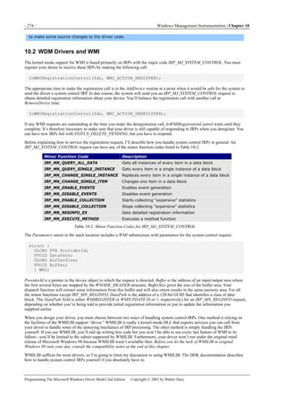
![10.2 WDM Drivers and WMI - 275 -
Programming The Microsoft Windows Driver Model 2nd Edition Copyright © 2003 by Walter Oney
10.2.1 Delegating IRPs to WMILIB
In your dispatch routine for system control IRPs, you delegate most of the work to WMILIB with code like the following:
WMIGUIDREGINFO guidlist[] = {
{&Wmi42_GUID, 1, 0},
};
WMILIB_CONTEXT libinfo = {
arraysize(guidlist),
guidlist,
QueryRegInfo,
QueryDataBlock,
SetDataBlock,
SetDataItem,
ExecuteMethod,
FunctionControl,
};
NTSTATUS DispatchWmi(IN PDEVICE_OBJECT fdo, IN PIRP Irp)
{
PDEVICE_EXTENSION pdx = (PDEVICE_EXTENSION) fdo->DeviceExtension;
NTSTATUS status;
SYSCTL_IRP_DISPOSITION disposition;
status = WmiSystemControl(&libinfo, fdo, Irp, &disposition);
switch (disposition)
{
case IrpProcessed:
break;
case IrpNotCompleted:
IoCompleteRequest(Irp, IO_NO_INCREMENT);
break;
default:
case IrpNotWmi:
case IrpForward:
IoSkipCurrentIrpStackLocation(Irp);
status = IoCallDriver(pdx->LowerDeviceObject, Irp);
break;
}
return status;
}
1. The WMILIB_CONTEXT structure declared at file scope describes the class GUIDs your driver supports and lists several
callback functions that WMILIB uses to handle WMI requests in the appropriate device-dependent and driver-dependent
way. It’s OK to use a static context structure if the information in it doesn’t change from one IRP to the next.
2. This statement calls WMILIB to handle the IRP. We pass the address of our WMILIB_CONTEXT structure.
WmiSystemControl returns two pieces of information: an NTSTATUS code and a SYSCTL_IRP_DISPOSITION value.
3. Depending on the disposition code, we might have additional work to perform on this IRP. If the code is IrpProcessed,
the IRP has already been completed and we need do nothing more with it. This case would be the normal one for minor
functions other than IRP_MN_REGINFO.
4. If the disposition code is IrpNotCompleted, completing the IRP is our responsibility. This case would be the normal one
for IRP_MN_REGINFO. WMILIB has already filled in the IoStatus block of the IRP, so we need only call
IoCompleteRequest.
5. The default and IrpNotWmi cases shouldn’t arise in Windows XP. We’d get to the default label if we weren’t handling all
possible disposition codes; we’d get to the IrpNotWmi case label if we sent an IRP to WMILIB that didn’t have one of the](https://image.slidesharecdn.com/2-programming-151105001030-lva1-app6892/85/2-programming-the-microsoft-windows-driver-model-2nd-edition-293-320.jpg)
![- 278 - Windows Management Instrumentation | Chapter 10
Programming The Microsoft Windows Driver Model 2nd Edition Copyright © 2003 by Walter Oney
PWmi42 pvalue = (PWmi42) buffer;
pvalue->TheAnswer = pdx->TheAnswer;
instlength[0] = Wmi42_SIZE;
return WmiCompleteRequest(fdo, Irp, STATUS_SUCCESS,
Wmi42_SIZE, IO_NO_INCREMENT);
}
1. The WMI subsystem should already have verified that we’re being queried for an instance of a class that we actually
support. Thus, guidindex should ordinarily be within the bounds of the GUID list, and instindex and instcount ought not
to exceed the number of instances we’ve said we own. If, however, we’ve just changed our registration information, we
might be servicing a request that was already “in flight,” and these tests would be needed to avoid mistakes.
2. We’re obliged to make this check to verify that the buffer area is large enough to accommodate the data and data length
values we’re going to put there. The first part of the test—is there an instlength array?—is boilerplate. The second part of
the test—is the buffer big enough for a Wmi42 structure?—is where we verify that all of our data values will fit.
3. The buffer parameter points to a memory area where we can put our data. The instlength parameter points to an array
where we’re supposed to place the length of each data instance we’re returning. Here we install the single data value our
schema calls for—the value of the TheAnswer property—and its length. Figuring out what TheAnswer actually is
numerically is left as an exercise for the reader.
4. The WMILIB specification requires us to complete the IRP by calling the WmiCompleteRequest helper routine. The
fourth argument indicates how much of the buffer area we used for data values. By now, the other arguments should be
self-explanatory.
Figure 10-4. Control flow for data queries.
The SetDataBlock Callback
The system might ask you to change an entire instance of one of your classes by sending you an
IRP_MN_CHANGE_SINGLE_INSTANCE request. WmiSystemControl processes this IRP by calling your SetDataBlock
callback routine. A simple version of this routine might look like this:
NTSTATUS SetDataBlock(PDEVICE_OBJECT fdo, PIRP Irp,
ULONG guidindex, ULONG instindex, ULONG bufsize,
PUCHAR buffer)
{
PDEVICE_EXTENSION pdx = (PDEVICE_EXTENSION) fdo->DeviceExtension;](https://image.slidesharecdn.com/2-programming-151105001030-lva1-app6892/85/2-programming-the-microsoft-windows-driver-model-2nd-edition-296-320.jpg)
![- 280 - Windows Management Instrumentation | Chapter 10
Programming The Microsoft Windows Driver Model 2nd Edition Copyright © 2003 by Walter Oney
however, use the “-h” option of WMIMOFCK as described earlier in this chapter, because there’s no good alternative for
getting the correct structure mapping.
10.2.2 Advanced Features
The preceding discussion covers much of what you need to know to provide meaningful performance information for metering
applications. Use your imagination here: instead of providing just a single statistic (TheAnswer), you can accumulate and
return any number of performance measures that are relevant to your specific device. You can support some additional WMI
features for more specialized purposes. I’ll discuss these features now.
Dealing with Multiple Instances
WMI allows you to create multiple instances of a particular class data block for a single device object. You might want to
provide multiple instances if your device is a controller or some other device in to which other devices plug; each instance
might represent data about one of the child devices. Mechanically, you specify the number of instances of a class in the
WMIGUIDREGINFO structure for the GUID associated with the class. If WMI42 had three different instances of its standard
data block, for example, it would have used the following GUID list in its WMILIB_CONTEXT structure:
WMIGUIDREGINFO guidlist[] = {
{&Wmi42_GUID, 3, 0},
};
The only difference between this GUID list and the one I showed you earlier is that the instance count here is 3 instead of 1.
This list declares that there will be three instances of the WMI42 data block, each with its own value for the three properties
(that is, InstanceName, Active, and TheAnswer) that belong in that block.
If the number of instances changes over time, you can call IoWmiRegistrationControl with the action code
WMIREG_ACTION_UPDATE_GUID to cause the system to send you another registration request, which you’ll process using
an updated copy of your WMILIB_CONTEXT structure. If you’re going to be changing your registration information, you
should probably allocate the WMILIB_CONTEXT structure and GUID list from the free pool rather than use static variables, by
the way.
If user-mode code were to enumerate all instances of GUID_WMI42_SCHEMA, it would find three instances. This result might
present a confusing picture to user-mode code, though. Depending on which WDM platform you’re running on, it may be
difficult to tell a priori that the three instances disclosed by the enumeration belong to a single device, as opposed to a situation
in which three WMI42 devices each expose a single instance of the same class. To allow WMI clients to sort out the difference
between the two situations, your schema should include a property (a device name or the like) that can function as a key.
Once you allow for the possibility of multiple instances, several of your WMILIB callbacks will require changes from the
simple examples I showed you earlier. In particular:
QueryDataBlock should be able to return the data block for a single instance or for any number of instances beginning at
a specific index.
SetDataBlock should interpret its instance number argument to decide which instance to change.
SetDataItem should likewise interpret its instance number argument to locate the instance within which the affected data
item will be found.
Figure 10-5. Getting multiple data block instances.
Figure 10-5 illustrates how your QueryDataBlock function uses the output buffer when it’s asked to provide more than one
instance of a data block. Imagine that you were asked to provide data for two instances beginning at instance number 2. You’ll
copy the data values, which I’ve shown as being of different sizes, into the data buffer. You start each instance on an 8-byte](https://image.slidesharecdn.com/2-programming-151105001030-lva1-app6892/85/2-programming-the-microsoft-windows-driver-model-2nd-edition-298-320.jpg)
![10.2 WDM Drivers and WMI - 281 -
Programming The Microsoft Windows Driver Model 2nd Edition Copyright © 2003 by Walter Oney
boundary. You indicate the total number of bytes you consume when you complete the query, and you indicate the lengths of
each individual instance by filling in the instlength array, as shown in the figure.
Instance Naming
Each instance of a WMI class has a unique name. Consumers who know the name of an instance can perform queries and
invoke method routines. Consumers who don’t know the name or names of the instance or instances you provide can learn
them by enumerating the class. In any case, you’re responsible for generating the names that consumers use or discover.
I showed you the simplest way—from the driver’s perspective, that is—of naming instances of a custom data block, which is
to request that WMI automatically generate a static, unique name based on the name of the PDO for your device. If your PDO
has the name RootSAMPLE0000, for example, a PDO-based name for a single instance of a given data block will be
RootSAMPLE0000_0.
Basing instance names on the PDO name is obviously convenient because all you need to do in the driver is set the
WMIREG_FLAG_INSTANCE_PDO flag in the flags variable that WMILIB passes to your QueryRegInfo callback routine. The
author of a consumer application can’t know what this name will be, however, because the name will vary depending on how
your device was installed. To make the instance names slightly more predictable, you can elect to use a constant base name for
object instances instead. You indicate this choice by responding in the following way to the registration query:
NTSTATUS QueryRegInfo(PDEVICE_OBJECT fdo, PULONG flags,
PUNICODE_STRING instname, PUNICODE_STRING* regpath,
PUNICODE_STRING resname, PDEVICE_OBJECT* pdo)
{
*flags = WMIREG_FLAG_INSTANCE_BASENAME;
*regpath = &servkey;
RtlInitUnicodeString(resname, L"MofResource");
static WCHAR basename[] = L"WMIEXTRA";
instname->Buffer = (PWCHAR) ExAllocatePool(PagedPool, sizeof(basename));
if (!instname->Buffer)
return STATUS_INSUFFICIENT_RESOURCES;
instname->MaximumLength = sizeof(basename);
instname->Length = sizeof(basename) - 2;
RtlCopyMemory(instname->Buffer, basename, sizeof(basename));
}
The parts of this function that differ from the previous example of QueryRegInfo are in boldface. In the WMIEXTRA sample,
only one instance of each data block exists, and each receives the instance name WMIEXTRA with no additional decoration.
If you elect to use a base name, try to avoid generic names such as Toys because of the confusion that can ensue. The purpose
of this feature is to let you use specific names such as TailspinToys.
In some circumstances, static instance names won’t suit your needs. If you maintain a population of data blocks that changes
frequently, using static names means that you have to request a registration update each time the population changes. The
update is relatively expensive, and you should avoid requesting one often. You can assign dynamic instance names to the
instances of your data blocks instead of static names. The instance names then become part of the queries and replies that you
deal with in your driver. Unfortunately, WMILIB doesn’t support the use of dynamic instance names. To use this feature,
therefore, you’ll have to fully implement support for the IRP_MJ_SYSTEM_CONTROL requests that WMILIB would
other](https://image.slidesharecdn.com/2-programming-151105001030-lva1-app6892/85/2-programming-the-microsoft-windows-driver-model-2nd-edition-299-320.jpg)
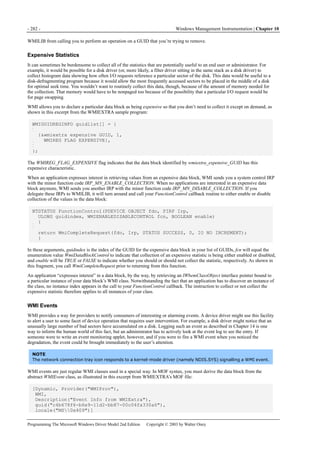

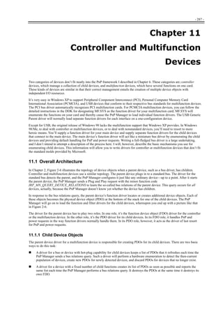
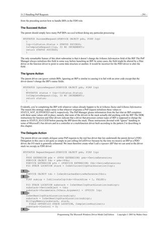
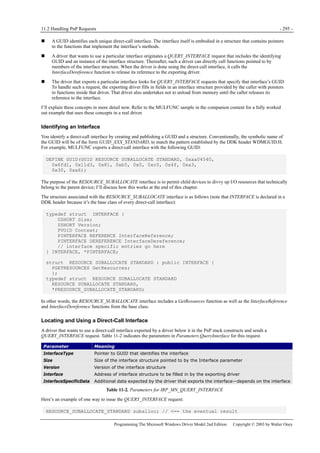
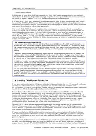

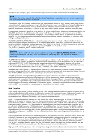
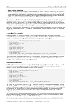
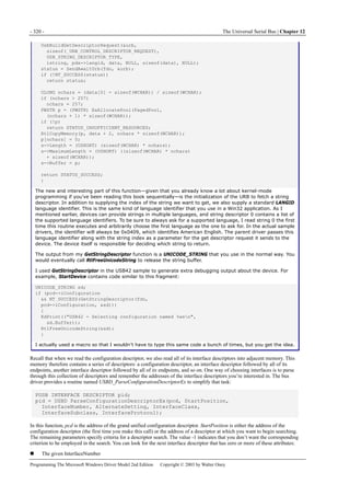
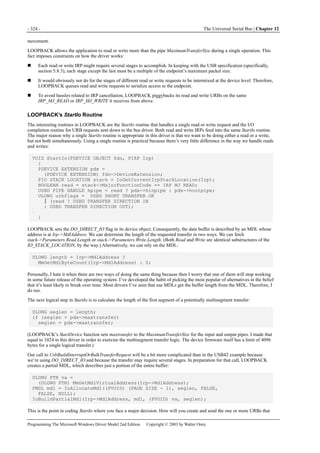
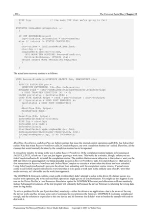
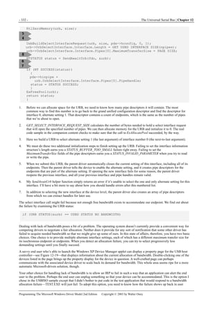
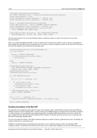
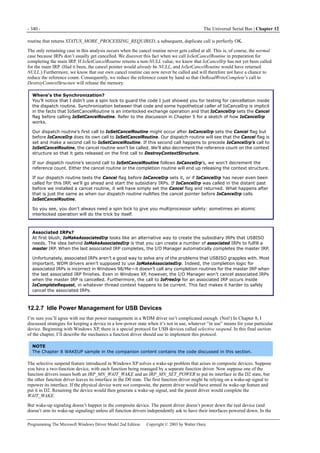

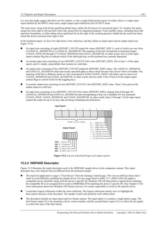
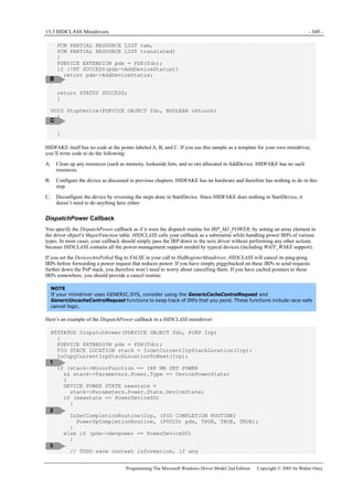
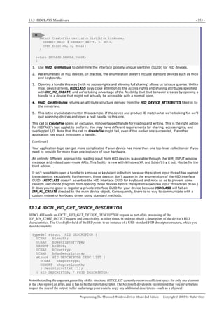
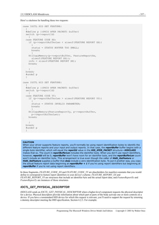


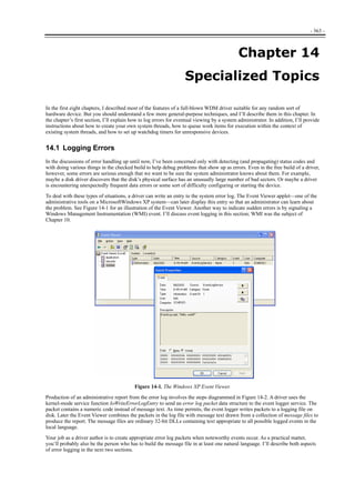
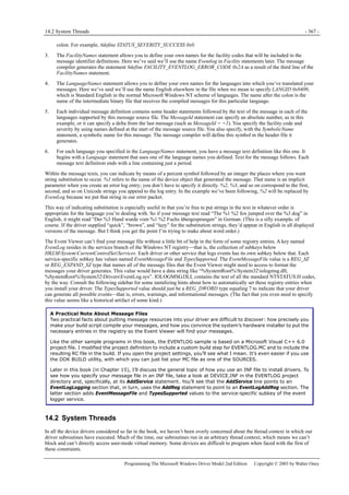
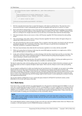
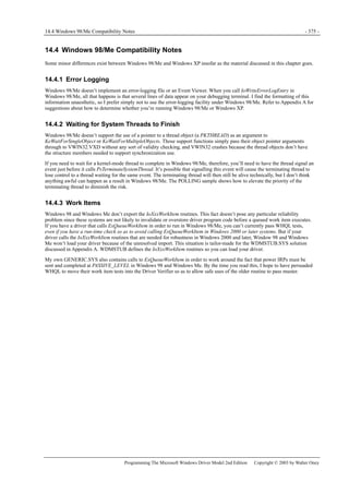

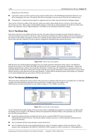
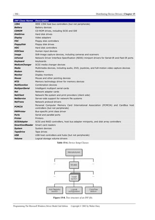
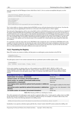
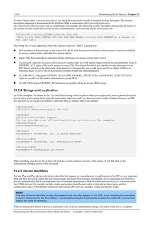
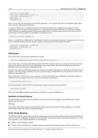
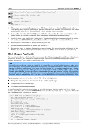
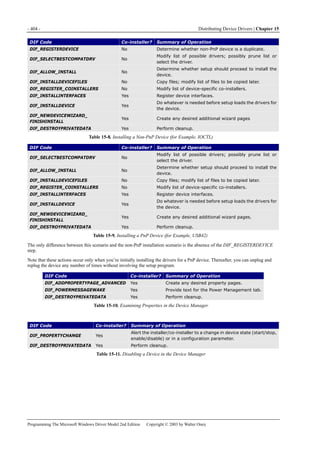
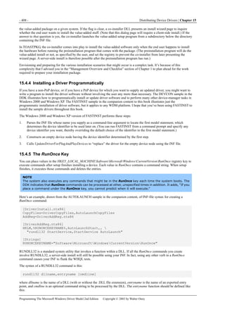
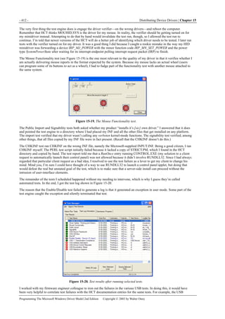
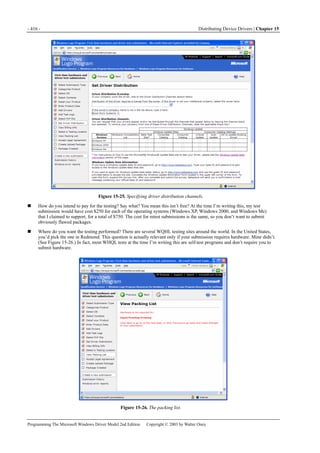

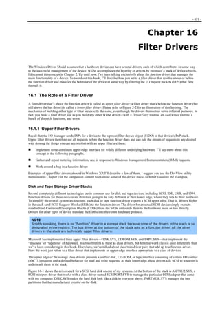
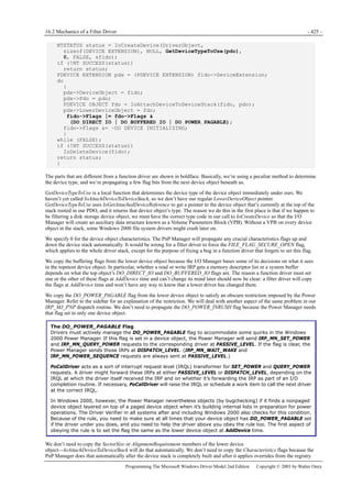
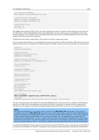
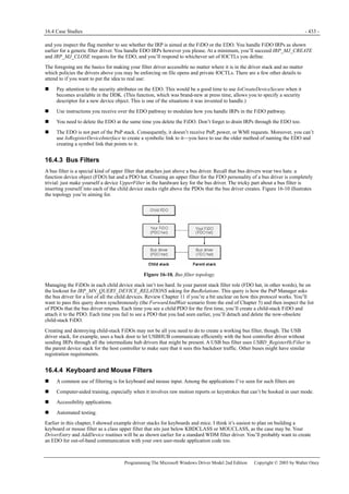
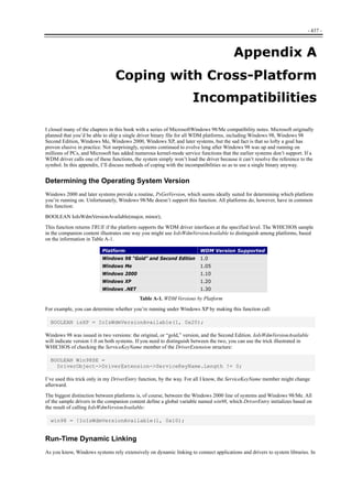
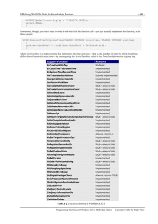

This document provides an overview of programming device drivers for the Windows Driver Model (WDM). It discusses the basic structure of WDM drivers, including the driver entry point, device objects, I/O request packets, and Plug and Play support. It also covers key programming techniques for kernel-mode drivers such as memory management, synchronization, power management, and handling I/O control operations. The document is intended to help programmers begin developing their own WDM drivers.


![Revo Uninstaller Pro 5.2.6 Crack + License Key 2025 [Full Latest]](https://cdn.slidesharecdn.com/ss_thumbnails/windowsntinternals-chapter5-250311141151-a04115dd-250311182343-70671553-250325161717-8b824cb4-thumbnail.jpg?width=640&height=640&fit=bounds)


