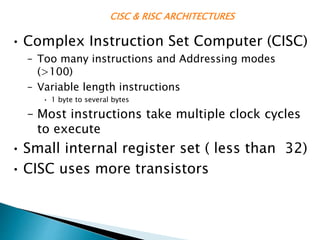
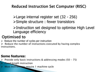
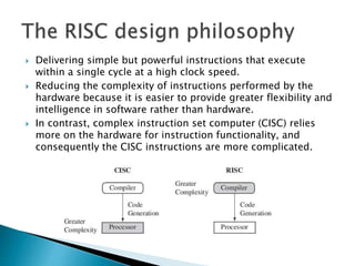
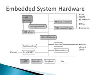
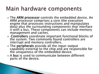
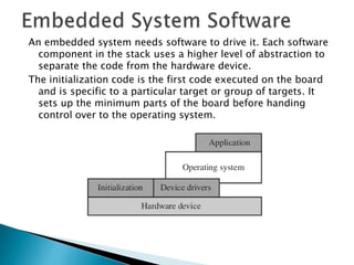
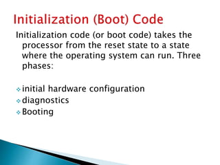
SlideShare a Scribd company logo
ARM Processor architecture
CISC & RISC ARCHITECTURES
• Complex Instruction Set Computer (CISC)
– Too many instructions and Addressing modes
(>100)
– Variable length instructions
• 1 byte to several bytes
– Most instructions take multiple clock cycles
to execute
• Small internal register set ( less than 32)
• CISC uses more transistors
CISC vs RISC
Reduced Instruction Set Computer (RISC)
Optimised to
 Reduce the number of cycles per instruction
 Reduce the number of instructions executed by having complex
instructions.
Some features:
 Provide only basic instructions & addressing modes (50 - 75)
 Fixed length instruction
 Most Instructions require 1 machine cycle
Large internal register set (32 - 256)
Simple structure : fewer transistors
Instruction set designed to optimise High Level
Language efficiency
CISC & RISC ARCHITECTURES
• Way back in late 1970’s, researchers were shocked to
notice that CISC processors were spending most of their
time performing relatively simple instructions.
It was also recognized that complex instructions
required potentially complex decoding circuit.
Reduction in complexity could lead to
improvement in execution time.
The top 10 instructions for the 80x86.
Rank 80x86 instruction Integer average (% total executed)
1 load 22%
2 conditional branch 20%
3 compare 16%
4 store 12%
5 add 8%
6 and 6%
7 sub 5%
8 move register-register 4%
9 call 1%
10 return 1%
Total 96%
Simple instructions dominate this list, and are responsible
for 96% of the instructions executed.
 Delivering simple but powerful instructions that execute
within a single cycle at a high clock speed.
 Reducing the complexity of instructions performed by the
hardware because it is easier to provide greater flexibility and
intelligence in software rather than hardware.
 In contrast, complex instruction set computer (CISC) relies
more on the hardware for instruction functionality, and
consequently the CISC instructions are more complicated.
 The ARM processor controls the embedded device. An
ARM processor comprises a core (the execution
engine that processes instructions and manipulates
data) plus the surrounding components that interface
it with a bus. These components can include memory
management and caches.
 Controllers coordinate important functional blocks of
the system. Two commonly found controllers are
interrupt and memory controllers.
 The peripherals provide all the input-output
capability external to the chip and are responsible for
the uniqueness of the embedded device.
 A bus is used to communicate between different
parts of the device.
Embedded devices use an on-chip bus that is internal to the chip
and that allows different peripheral devices to be interconnected
with an ARM core.
There are two different classes of devices attached to the bus.
 The ARM processor core is a bus master—a logical device
capable of initiating a data transfer with another device across the
same bus.
 Peripherals tend to be bus slaves —logical devices capable only of
responding to a transfer request from a bus master device.
A bus has two architecture levels.
1. Physical level that covers the electrical characteristics and bus
width (16, 32, or 64 bits).
2. Protocol—the logical rules that govern the communication
between the processor and a peripheral.
An embedded system has to have some form of memory to store and execute code.
You have to compare price, performance, and power consumption when deciding
upon specific memory characteristics, such as hierarchy, width, and type.
Hierarchy
All computer systems have memory arranged in some form of hierarchy.
The fastest memory cache is physically located nearer the ARM processor core and
the slowest secondary memory is set further away. Generally the closer memory is
to the processor core, the more it costs and the smaller its capacity.
The cache is placed between main memory and the core. It is used to speed up data
transfer between the processor and main memory.
capacity order:
Cache memory < main memory < Secondary storage memory
processor
Registers
Main Memory
Cache
Secondary Memory e.g. Hard Drive
The memory width is the number of bits the memory returns
on each access—typically 8, 16, 32, or 64 bits. The memory
width has a direct effect on the overall performance and cost
ratio.
If you have an un-cached system using 32-bit ARM
instructions and 16-bit-wide memory chips, then the
processor will have to make two memory fetches per
instruction. Each fetch requires two 16-bit loads. this reduce
system performance, but the benefit is that 16-bit memory
is less expensive.
In contrast, if the core executes 16-bit Thumb instructions, it
will achieve better performance with a 16-bit memory. The
higher performance is a result of the core making only a
single fetch to memory to load an instruction. Hence, using
Thumb instructions with 16-bit-wide memory devices
provides both improved performance and reduced cost.
Instruction
size
8-bit
memory
16-bit
memory
32-bit
memory
ARM 32-bit 4 cycles 2 cycles 1 cycles
Thumb 16-
bit
2 cycles 1 cycles 1 cycles
 Read-only memory (ROM) is the least flexible of all memory
types because it contains an image that is permanently set
at production time and cannot be reprogrammed. ROMs are
used in high-volume devices that require no updates or
corrections. Many devices also use a ROM to hold boot code.
 Flash ROM: Its main use is for holding the device firmware
or storing long-term data that needs to be preserved after
power is off. The erasing and writing of flash ROM are
completely software controlled with no additional hardware
circuits required, which reduces the manufacturing costs.
Flash ROM has become the most popular of the read-only
memory types and is currently being used as an alternative
for mass or secondary storage.
Dynamic random access memory (DRAM) is the most commonly used RAM for
devices.
It has the lowest cost per megabyte compared with other types of RAM. DRAM is
dynamic—it needs to have its storage cells refreshed and given a new electronic
charge every few milliseconds, so you need to set up a DRAM controller before
using the memory.
Static random access memory (SRAM) is faster than the more traditional DRAM, but
requires more silicon area. SRAM is static—the RAM does not require refreshing. The
access time for SRAM is considerably shorter than the equivalent DRAM because SRAM
does not require a pause between data accesses. Because of its higher cost, it is used
mostly for smaller high-speed tasks, such as fast memory and caches.
Synchronous dynamic random access memory (SDRAM) is one of many subcategories
of DRAM. It can run at much higher clock speeds than conventional memory. SDRAM
synchronizes itself with the processor bus because it is clocked. Internally the data is
fetched from memory cells, pipelined, and finally brought out on the bus in a burst.
The old-style DRAM is asynchronous, so does not burst as efficiently as SDRAM
Embedded systems that interact with the outside world need some
form of peripheral device. A peripheral device performs input and
output functions for the chip by connecting to other devices or
sensors that are off-chip. Each peripheral device usually
performs a single function and may reside on-chip.
All ARM peripherals are memory mapped—the programming
interface is a set of memory-addressed registers. The address of
these registers is an offset from a specific peripheral base
address.
Controllers are specialized peripherals that implement higher levels
of functionality within an embedded system. Two important types
of controllers are memory controllers and interrupt controllers.
Memory controllers connect different types of memory to the
processor bus. On power-up a memory controller is
configured in hardware to allow certain memory devices to be
active. These memory devices allow the initialization code to
be executed.
When a peripheral or device requires attention, it raises
an interrupt to the processor.
An interrupt controller provides a programmable
governing policy that allows software to determine
which peripheral or device can interrupt the
processor at any specific time by setting the
appropriate bits in the interrupt controller registers.
The standard interrupt controller sends an interrupt signal to
the processor core when an external device requests
servicing. It can be programmed to ignore or mask an
individual device or set of devices. The interrupt handler
determines which device requires servicing by reading a
device bitmap register in the interrupt controller.
The vector interrupt controller (VIC) is more powerful than the
standard interrupt controller because it prioritizes
interrupts and simplifies the determination of which device
caused the interrupt. After associating a priority and a
handler address with each interrupt, the VIC only asserts an
interrupt signal to the core if the priority of a new interrupt
is higher than the currently executing interrupt handler.
An embedded system needs software to drive it. Each software
component in the stack uses a higher level of abstraction to
separate the code from the hardware device.
The initialization code is the first code executed on the board
and is specific to a particular target or group of targets. It
sets up the minimum parts of the board before handing
control over to the operating system.
Initialization code (or boot code) takes the
processor from the reset state to a state
where the operating system can run. Three
phases:
 initial hardware configuration
 diagnostics
 Booting
Initial hardware configuration involves setting up the
target platform so it can boot an image. Although the
target platform itself comes up in a standard
configuration, this configuration normally requires
modification to satisfy the requirements of the booted
image.
Diagnostic code tests the system by exercising the
hardware target to check if the target is in working
order. The primary purpose of diagnostic code is fault
identification and isolation.
Booting involves loading an image and handing control
over to that image.
Loading an image involves anything from copying
program and data into RAM. Once booted, the system
hands over control by modifying the program counter to
point into the start of the image.
 The initialization process prepares the hardware
for an operating system to take control.
 An operating system organizes the system
resources: the peripherals, memory and
processing time.
 With an operating system controlling these
resources, they can be efficiently used by
different applications running within the
operating system environment.
Two main categories: real-time operating systems
(RTOSs) and platform operating systems
RTOSs provide guaranteed response times to events. A
hard real-time application requires a guaranteed
response to work at all. It do not need secondary
storage.
Platform operating systems require a memory
management unit to manage large, non-real-time
applications. It need secondary storage.
**there are operating systems that use an ARM core
with a memory management unit and have real-time
characteristics.

More Related Content

What's hot

Arm instruction set
Arm instruction setArm instruction set
Arm instruction set
Mathivanan Natarajan
 
Unit vi (1)
Unit vi (1)Unit vi (1)
Unit vi (1)
Siva Nageswararao
 
Unit II arm 7 Instruction Set
Unit II arm 7 Instruction SetUnit II arm 7 Instruction Set
Unit II arm 7 Instruction Set
Dr. Pankaj Zope
 
ARM Architecture
ARM ArchitectureARM Architecture
ARM Architecture
Kshitij Gorde
 
Assembly Language and microprocessor
Assembly Language and microprocessorAssembly Language and microprocessor
Assembly Language and microprocessor
Khaled Sany
 
Real Time Operating system (RTOS) - Embedded systems
Real Time Operating system (RTOS) - Embedded systemsReal Time Operating system (RTOS) - Embedded systems
Real Time Operating system (RTOS) - Embedded systems
Hariharan Ganesan
 
06. thumb instructions
06. thumb instructions06. thumb instructions
06. thumb instructions
balaji raja rajan Venkatachalam
 
Introduction to ARM LPC2148
Introduction to ARM LPC2148Introduction to ARM LPC2148
Introduction to ARM LPC2148
Veera Kumar
 
Lect 2 ARM processor architecture
Lect 2 ARM processor architectureLect 2 ARM processor architecture
Lect 2 ARM processor architecture
Dr.YNM
 
Embedded system introduction
Embedded system introductionEmbedded system introduction
Embedded system introduction
RajalakshmiSermadurai
 
Pin diagram 8085 microprocessor(For College Seminars)
Pin diagram 8085 microprocessor(For College Seminars)Pin diagram 8085 microprocessor(For College Seminars)
Pin diagram 8085 microprocessor(For College Seminars)
Naman Joshi
 
RISC - Reduced Instruction Set Computing
RISC - Reduced Instruction Set ComputingRISC - Reduced Instruction Set Computing
RISC - Reduced Instruction Set Computing
Tushar Swami
 
1: Interfacing using ARM Cortex M4 || IEEE SSCS AlexSC
1: Interfacing using ARM Cortex M4 || IEEE SSCS AlexSC 1: Interfacing using ARM Cortex M4 || IEEE SSCS AlexSC
1: Interfacing using ARM Cortex M4 || IEEE SSCS AlexSC
IEEE SSCS AlexSC
 
Semiconductor memory
Semiconductor memorySemiconductor memory
Semiconductor memory
Then Murugeshwari
 
Arm modes
Arm modesArm modes
Arm modes
abhi165
 
8257 DMA Controller
8257 DMA Controller8257 DMA Controller
8257 DMA Controller
ShivamSood22
 
Embedded linux
Embedded linuxEmbedded linux
Embedded linux
Wingston
 
ARM CORTEX M3 PPT
ARM CORTEX M3 PPTARM CORTEX M3 PPT
ARM CORTEX M3 PPT
Gaurav Verma
 
TMS320C6X Architecture
TMS320C6X ArchitectureTMS320C6X Architecture
TMS320C6X Architecture
Shweta Tripathi
 
Arm cortex-m4 programmer model
Arm cortex-m4 programmer modelArm cortex-m4 programmer model
Arm cortex-m4 programmer model
Mohammed Gomaa
 

What's hot (20)

Arm instruction set
Arm instruction setArm instruction set
Arm instruction set
 
Unit vi (1)
Unit vi (1)Unit vi (1)
Unit vi (1)
 
Unit II arm 7 Instruction Set
Unit II arm 7 Instruction SetUnit II arm 7 Instruction Set
Unit II arm 7 Instruction Set
 
ARM Architecture
ARM ArchitectureARM Architecture
ARM Architecture
 
Assembly Language and microprocessor
Assembly Language and microprocessorAssembly Language and microprocessor
Assembly Language and microprocessor
 
Real Time Operating system (RTOS) - Embedded systems
Real Time Operating system (RTOS) - Embedded systemsReal Time Operating system (RTOS) - Embedded systems
Real Time Operating system (RTOS) - Embedded systems
 
06. thumb instructions
06. thumb instructions06. thumb instructions
06. thumb instructions
 
Introduction to ARM LPC2148
Introduction to ARM LPC2148Introduction to ARM LPC2148
Introduction to ARM LPC2148
 
Lect 2 ARM processor architecture
Lect 2 ARM processor architectureLect 2 ARM processor architecture
Lect 2 ARM processor architecture
 
Embedded system introduction
Embedded system introductionEmbedded system introduction
Embedded system introduction
 
Pin diagram 8085 microprocessor(For College Seminars)
Pin diagram 8085 microprocessor(For College Seminars)Pin diagram 8085 microprocessor(For College Seminars)
Pin diagram 8085 microprocessor(For College Seminars)
 
RISC - Reduced Instruction Set Computing
RISC - Reduced Instruction Set ComputingRISC - Reduced Instruction Set Computing
RISC - Reduced Instruction Set Computing
 
1: Interfacing using ARM Cortex M4 || IEEE SSCS AlexSC
1: Interfacing using ARM Cortex M4 || IEEE SSCS AlexSC 1: Interfacing using ARM Cortex M4 || IEEE SSCS AlexSC
1: Interfacing using ARM Cortex M4 || IEEE SSCS AlexSC
 
Semiconductor memory
Semiconductor memorySemiconductor memory
Semiconductor memory
 
Arm modes
Arm modesArm modes
Arm modes
 
8257 DMA Controller
8257 DMA Controller8257 DMA Controller
8257 DMA Controller
 
Embedded linux
Embedded linuxEmbedded linux
Embedded linux
 
ARM CORTEX M3 PPT
ARM CORTEX M3 PPTARM CORTEX M3 PPT
ARM CORTEX M3 PPT
 
TMS320C6X Architecture
TMS320C6X ArchitectureTMS320C6X Architecture
TMS320C6X Architecture
 
Arm cortex-m4 programmer model
Arm cortex-m4 programmer modelArm cortex-m4 programmer model
Arm cortex-m4 programmer model
 

Similar to ARM Processor architecture

Module-2 Instruction Set Cpus.pdf
Module-2 Instruction Set Cpus.pdfModule-2 Instruction Set Cpus.pdf
Module-2 Instruction Set Cpus.pdf
Sitamarhi Institute of Technology
 
Microcontroller(18CS44) module 1
Microcontroller(18CS44)  module 1Microcontroller(18CS44)  module 1
Microcontroller(18CS44) module 1
Swetha A
 
15CS44 MP & MC Module 4
15CS44 MP & MC Module 415CS44 MP & MC Module 4
15CS44 MP & MC Module 4
RLJIT
 
Mces MOD 1.pptx
Mces MOD 1.pptxMces MOD 1.pptx
Mces MOD 1.pptx
RadhaC10
 
IRJET- Design And VLSI Verification of DDR SDRAM Controller Using VHDL
IRJET- Design And VLSI Verification of DDR SDRAM Controller Using VHDLIRJET- Design And VLSI Verification of DDR SDRAM Controller Using VHDL
IRJET- Design And VLSI Verification of DDR SDRAM Controller Using VHDL
IRJET Journal
 
Lesson three hardware basics
Lesson three hardware basicsLesson three hardware basics
Lesson three hardware basics
Mik Endale
 
Basic computer hardware terminology
Basic computer hardware terminologyBasic computer hardware terminology
Basic computer hardware terminology
Imtiyaz Husaini
 
Internal components technical
Internal components technicalInternal components technical
Internal components technical
LiamSewell
 
Coa presentation3
Coa presentation3Coa presentation3
Coa presentation3
rickypatel151
 
COMPONENTS OF SYSTEM UNIT
COMPONENTS OF SYSTEM UNITCOMPONENTS OF SYSTEM UNIT
COMPONENTS OF SYSTEM UNIT
arunakshidatta
 
Components of the System Unit.pdf
Components of the System Unit.pdfComponents of the System Unit.pdf
Components of the System Unit.pdf
ODINARARCH
 
11. Computer Systems Hardware 1
11. Computer Systems   Hardware 111. Computer Systems   Hardware 1
11. Computer Systems Hardware 1
New Era University
 
esunit1.pptx
esunit1.pptxesunit1.pptx
esunit1.pptx
AmitKumar7572
 
Multilevel arch & str org.& mips, 8086, memory
Multilevel arch & str org.& mips, 8086, memoryMultilevel arch & str org.& mips, 8086, memory
Multilevel arch & str org.& mips, 8086, memory
Mahesh Kumar Attri
 
CPU & RAM
CPU & RAMCPU & RAM
CPU & RAM
Redoan Ur Rahman
 
System Unit
System UnitSystem Unit
System Unit
Reina Mae Salido
 
12429908.ppt
12429908.ppt12429908.ppt
12429908.ppt
ssuser4ca1eb
 
Computer Hardware Components
Computer Hardware ComponentsComputer Hardware Components
Ram and types of ram.Cache
Ram and types of ram.CacheRam and types of ram.Cache
Ram and types of ram.Cache
hamza mukhtiar
 
Computer hardware ppt1
Computer hardware ppt1Computer hardware ppt1

Similar to ARM Processor architecture (20)

Module-2 Instruction Set Cpus.pdf
Module-2 Instruction Set Cpus.pdfModule-2 Instruction Set Cpus.pdf
Module-2 Instruction Set Cpus.pdf
 
Microcontroller(18CS44) module 1
Microcontroller(18CS44)  module 1Microcontroller(18CS44)  module 1
Microcontroller(18CS44) module 1
 
15CS44 MP & MC Module 4
15CS44 MP & MC Module 415CS44 MP & MC Module 4
15CS44 MP & MC Module 4
 
Mces MOD 1.pptx
Mces MOD 1.pptxMces MOD 1.pptx
Mces MOD 1.pptx
 
IRJET- Design And VLSI Verification of DDR SDRAM Controller Using VHDL
IRJET- Design And VLSI Verification of DDR SDRAM Controller Using VHDLIRJET- Design And VLSI Verification of DDR SDRAM Controller Using VHDL
IRJET- Design And VLSI Verification of DDR SDRAM Controller Using VHDL
 
Lesson three hardware basics
Lesson three hardware basicsLesson three hardware basics
Lesson three hardware basics
 
Basic computer hardware terminology
Basic computer hardware terminologyBasic computer hardware terminology
Basic computer hardware terminology
 
Internal components technical
Internal components technicalInternal components technical
Internal components technical
 
Coa presentation3
Coa presentation3Coa presentation3
Coa presentation3
 
COMPONENTS OF SYSTEM UNIT
COMPONENTS OF SYSTEM UNITCOMPONENTS OF SYSTEM UNIT
COMPONENTS OF SYSTEM UNIT
 
Components of the System Unit.pdf
Components of the System Unit.pdfComponents of the System Unit.pdf
Components of the System Unit.pdf
 
11. Computer Systems Hardware 1
11. Computer Systems   Hardware 111. Computer Systems   Hardware 1
11. Computer Systems Hardware 1
 
esunit1.pptx
esunit1.pptxesunit1.pptx
esunit1.pptx
 
Multilevel arch & str org.& mips, 8086, memory
Multilevel arch & str org.& mips, 8086, memoryMultilevel arch & str org.& mips, 8086, memory
Multilevel arch & str org.& mips, 8086, memory
 
CPU & RAM
CPU & RAMCPU & RAM
CPU & RAM
 
System Unit
System UnitSystem Unit
System Unit
 
12429908.ppt
12429908.ppt12429908.ppt
12429908.ppt
 
Computer Hardware Components
Computer Hardware ComponentsComputer Hardware Components
Computer Hardware Components
 
Ram and types of ram.Cache
Ram and types of ram.CacheRam and types of ram.Cache
Ram and types of ram.Cache
 
Computer hardware ppt1
Computer hardware ppt1Computer hardware ppt1
Computer hardware ppt1
 

Recently uploaded

22CYT12-Unit-V-E Waste and its Management.ppt
22CYT12-Unit-V-E Waste and its Management.ppt22CYT12-Unit-V-E Waste and its Management.ppt
22CYT12-Unit-V-E Waste and its Management.ppt
KrishnaveniKrishnara1
 
原版制作(unimelb毕业证书)墨尔本大学毕业证Offer一模一样
原版制作(unimelb毕业证书)墨尔本大学毕业证Offer一模一样原版制作(unimelb毕业证书)墨尔本大学毕业证Offer一模一样
原版制作(unimelb毕业证书)墨尔本大学毕业证Offer一模一样
obonagu
 
14 Template Contractual Notice - EOT Application
14 Template Contractual Notice - EOT Application14 Template Contractual Notice - EOT Application
14 Template Contractual Notice - EOT Application
SyedAbiiAzazi1
 
PPT on GRP pipes manufacturing and testing
PPT on GRP pipes manufacturing and testingPPT on GRP pipes manufacturing and testing
PPT on GRP pipes manufacturing and testing
anoopmanoharan2
 
introduction to solar energy for engineering.pdf
introduction to solar energy for engineering.pdfintroduction to solar energy for engineering.pdf
introduction to solar energy for engineering.pdf
ravindarpurohit26
 
BPV-GUI-01-Guide-for-ASME-Review-Teams-(General)-10-10-2023.pdf
BPV-GUI-01-Guide-for-ASME-Review-Teams-(General)-10-10-2023.pdfBPV-GUI-01-Guide-for-ASME-Review-Teams-(General)-10-10-2023.pdf
BPV-GUI-01-Guide-for-ASME-Review-Teams-(General)-10-10-2023.pdf
MIGUELANGEL966976
 
New techniques for characterising damage in rock slopes.pdf
New techniques for characterising damage in rock slopes.pdfNew techniques for characterising damage in rock slopes.pdf
New techniques for characterising damage in rock slopes.pdf
wisnuprabawa3
 
[JPP-1] - (JEE 3.0) - Kinematics 1D - 14th May..pdf
[JPP-1] - (JEE 3.0) - Kinematics 1D - 14th May..pdf[JPP-1] - (JEE 3.0) - Kinematics 1D - 14th May..pdf
[JPP-1] - (JEE 3.0) - Kinematics 1D - 14th May..pdf
awadeshbabu
 
Recycled Concrete Aggregate in Construction Part III
Recycled Concrete Aggregate in Construction Part IIIRecycled Concrete Aggregate in Construction Part III
Recycled Concrete Aggregate in Construction Part III
Aditya Rajan Patra
 
一比一原版(UMich毕业证)密歇根大学|安娜堡分校毕业证成绩单专业办理
一比一原版(UMich毕业证)密歇根大学|安娜堡分校毕业证成绩单专业办理一比一原版(UMich毕业证)密歇根大学|安娜堡分校毕业证成绩单专业办理
一比一原版(UMich毕业证)密歇根大学|安娜堡分校毕业证成绩单专业办理
zwunae
 
Technical Drawings introduction to drawing of prisms
Technical Drawings introduction to drawing of prismsTechnical Drawings introduction to drawing of prisms
Technical Drawings introduction to drawing of prisms
heavyhaig
 
Unbalanced Three Phase Systems and circuits.pptx
Unbalanced Three Phase Systems and circuits.pptxUnbalanced Three Phase Systems and circuits.pptx
Unbalanced Three Phase Systems and circuits.pptx
ChristineTorrepenida1
 
Adaptive synchronous sliding control for a robot manipulator based on neural ...
Adaptive synchronous sliding control for a robot manipulator based on neural ...Adaptive synchronous sliding control for a robot manipulator based on neural ...
Adaptive synchronous sliding control for a robot manipulator based on neural ...
IJECEIAES
 
Tutorial for 16S rRNA Gene Analysis with QIIME2.pdf
Tutorial for 16S rRNA Gene Analysis with QIIME2.pdfTutorial for 16S rRNA Gene Analysis with QIIME2.pdf
Tutorial for 16S rRNA Gene Analysis with QIIME2.pdf
aqil azizi
 
CHINA’S GEO-ECONOMIC OUTREACH IN CENTRAL ASIAN COUNTRIES AND FUTURE PROSPECT
CHINA’S GEO-ECONOMIC OUTREACH IN CENTRAL ASIAN COUNTRIES AND FUTURE PROSPECTCHINA’S GEO-ECONOMIC OUTREACH IN CENTRAL ASIAN COUNTRIES AND FUTURE PROSPECT
CHINA’S GEO-ECONOMIC OUTREACH IN CENTRAL ASIAN COUNTRIES AND FUTURE PROSPECT
jpsjournal1
 
A review on techniques and modelling methodologies used for checking electrom...
A review on techniques and modelling methodologies used for checking electrom...A review on techniques and modelling methodologies used for checking electrom...
A review on techniques and modelling methodologies used for checking electrom...
nooriasukmaningtyas
 
spirit beverages ppt without graphics.pptx
spirit beverages ppt without graphics.pptxspirit beverages ppt without graphics.pptx
spirit beverages ppt without graphics.pptx
Madan Karki
 
Building Electrical System Design & Installation
Building Electrical System Design & InstallationBuilding Electrical System Design & Installation
Building Electrical System Design & Installation
symbo111
 
RAT: Retrieval Augmented Thoughts Elicit Context-Aware Reasoning in Long-Hori...
RAT: Retrieval Augmented Thoughts Elicit Context-Aware Reasoning in Long-Hori...RAT: Retrieval Augmented Thoughts Elicit Context-Aware Reasoning in Long-Hori...
RAT: Retrieval Augmented Thoughts Elicit Context-Aware Reasoning in Long-Hori...
thanhdowork
 
哪里办理(csu毕业证书)查尔斯特大学毕业证硕士学历原版一模一样
哪里办理(csu毕业证书)查尔斯特大学毕业证硕士学历原版一模一样哪里办理(csu毕业证书)查尔斯特大学毕业证硕士学历原版一模一样
哪里办理(csu毕业证书)查尔斯特大学毕业证硕士学历原版一模一样
insn4465
 

Recently uploaded (20)

22CYT12-Unit-V-E Waste and its Management.ppt
22CYT12-Unit-V-E Waste and its Management.ppt22CYT12-Unit-V-E Waste and its Management.ppt
22CYT12-Unit-V-E Waste and its Management.ppt
 
原版制作(unimelb毕业证书)墨尔本大学毕业证Offer一模一样
原版制作(unimelb毕业证书)墨尔本大学毕业证Offer一模一样原版制作(unimelb毕业证书)墨尔本大学毕业证Offer一模一样
原版制作(unimelb毕业证书)墨尔本大学毕业证Offer一模一样
 
14 Template Contractual Notice - EOT Application
14 Template Contractual Notice - EOT Application14 Template Contractual Notice - EOT Application
14 Template Contractual Notice - EOT Application
 
PPT on GRP pipes manufacturing and testing
PPT on GRP pipes manufacturing and testingPPT on GRP pipes manufacturing and testing
PPT on GRP pipes manufacturing and testing
 
introduction to solar energy for engineering.pdf
introduction to solar energy for engineering.pdfintroduction to solar energy for engineering.pdf
introduction to solar energy for engineering.pdf
 
BPV-GUI-01-Guide-for-ASME-Review-Teams-(General)-10-10-2023.pdf
BPV-GUI-01-Guide-for-ASME-Review-Teams-(General)-10-10-2023.pdfBPV-GUI-01-Guide-for-ASME-Review-Teams-(General)-10-10-2023.pdf
BPV-GUI-01-Guide-for-ASME-Review-Teams-(General)-10-10-2023.pdf
 
New techniques for characterising damage in rock slopes.pdf
New techniques for characterising damage in rock slopes.pdfNew techniques for characterising damage in rock slopes.pdf
New techniques for characterising damage in rock slopes.pdf
 
[JPP-1] - (JEE 3.0) - Kinematics 1D - 14th May..pdf
[JPP-1] - (JEE 3.0) - Kinematics 1D - 14th May..pdf[JPP-1] - (JEE 3.0) - Kinematics 1D - 14th May..pdf
[JPP-1] - (JEE 3.0) - Kinematics 1D - 14th May..pdf
 
Recycled Concrete Aggregate in Construction Part III
Recycled Concrete Aggregate in Construction Part IIIRecycled Concrete Aggregate in Construction Part III
Recycled Concrete Aggregate in Construction Part III
 
一比一原版(UMich毕业证)密歇根大学|安娜堡分校毕业证成绩单专业办理
一比一原版(UMich毕业证)密歇根大学|安娜堡分校毕业证成绩单专业办理一比一原版(UMich毕业证)密歇根大学|安娜堡分校毕业证成绩单专业办理
一比一原版(UMich毕业证)密歇根大学|安娜堡分校毕业证成绩单专业办理
 
Technical Drawings introduction to drawing of prisms
Technical Drawings introduction to drawing of prismsTechnical Drawings introduction to drawing of prisms
Technical Drawings introduction to drawing of prisms
 
Unbalanced Three Phase Systems and circuits.pptx
Unbalanced Three Phase Systems and circuits.pptxUnbalanced Three Phase Systems and circuits.pptx
Unbalanced Three Phase Systems and circuits.pptx
 
Adaptive synchronous sliding control for a robot manipulator based on neural ...
Adaptive synchronous sliding control for a robot manipulator based on neural ...Adaptive synchronous sliding control for a robot manipulator based on neural ...
Adaptive synchronous sliding control for a robot manipulator based on neural ...
 
Tutorial for 16S rRNA Gene Analysis with QIIME2.pdf
Tutorial for 16S rRNA Gene Analysis with QIIME2.pdfTutorial for 16S rRNA Gene Analysis with QIIME2.pdf
Tutorial for 16S rRNA Gene Analysis with QIIME2.pdf
 
CHINA’S GEO-ECONOMIC OUTREACH IN CENTRAL ASIAN COUNTRIES AND FUTURE PROSPECT
CHINA’S GEO-ECONOMIC OUTREACH IN CENTRAL ASIAN COUNTRIES AND FUTURE PROSPECTCHINA’S GEO-ECONOMIC OUTREACH IN CENTRAL ASIAN COUNTRIES AND FUTURE PROSPECT
CHINA’S GEO-ECONOMIC OUTREACH IN CENTRAL ASIAN COUNTRIES AND FUTURE PROSPECT
 
A review on techniques and modelling methodologies used for checking electrom...
A review on techniques and modelling methodologies used for checking electrom...A review on techniques and modelling methodologies used for checking electrom...
A review on techniques and modelling methodologies used for checking electrom...
 
spirit beverages ppt without graphics.pptx
spirit beverages ppt without graphics.pptxspirit beverages ppt without graphics.pptx
spirit beverages ppt without graphics.pptx
 
Building Electrical System Design & Installation
Building Electrical System Design & InstallationBuilding Electrical System Design & Installation
Building Electrical System Design & Installation
 
RAT: Retrieval Augmented Thoughts Elicit Context-Aware Reasoning in Long-Hori...
RAT: Retrieval Augmented Thoughts Elicit Context-Aware Reasoning in Long-Hori...RAT: Retrieval Augmented Thoughts Elicit Context-Aware Reasoning in Long-Hori...
RAT: Retrieval Augmented Thoughts Elicit Context-Aware Reasoning in Long-Hori...
 
哪里办理(csu毕业证书)查尔斯特大学毕业证硕士学历原版一模一样
哪里办理(csu毕业证书)查尔斯特大学毕业证硕士学历原版一模一样哪里办理(csu毕业证书)查尔斯特大学毕业证硕士学历原版一模一样
哪里办理(csu毕业证书)查尔斯特大学毕业证硕士学历原版一模一样
 

ARM Processor architecture

  • 2. CISC & RISC ARCHITECTURES • Complex Instruction Set Computer (CISC) – Too many instructions and Addressing modes (>100) – Variable length instructions • 1 byte to several bytes – Most instructions take multiple clock cycles to execute • Small internal register set ( less than 32) • CISC uses more transistors
  • 3. CISC vs RISC Reduced Instruction Set Computer (RISC) Optimised to  Reduce the number of cycles per instruction  Reduce the number of instructions executed by having complex instructions. Some features:  Provide only basic instructions & addressing modes (50 - 75)  Fixed length instruction  Most Instructions require 1 machine cycle Large internal register set (32 - 256) Simple structure : fewer transistors Instruction set designed to optimise High Level Language efficiency
  • 4. CISC & RISC ARCHITECTURES • Way back in late 1970’s, researchers were shocked to notice that CISC processors were spending most of their time performing relatively simple instructions. It was also recognized that complex instructions required potentially complex decoding circuit. Reduction in complexity could lead to improvement in execution time.
  • 5. The top 10 instructions for the 80x86. Rank 80x86 instruction Integer average (% total executed) 1 load 22% 2 conditional branch 20% 3 compare 16% 4 store 12% 5 add 8% 6 and 6% 7 sub 5% 8 move register-register 4% 9 call 1% 10 return 1% Total 96% Simple instructions dominate this list, and are responsible for 96% of the instructions executed.
  • 6.  Delivering simple but powerful instructions that execute within a single cycle at a high clock speed.  Reducing the complexity of instructions performed by the hardware because it is easier to provide greater flexibility and intelligence in software rather than hardware.  In contrast, complex instruction set computer (CISC) relies more on the hardware for instruction functionality, and consequently the CISC instructions are more complicated.
  • 7.
  • 8.  The ARM processor controls the embedded device. An ARM processor comprises a core (the execution engine that processes instructions and manipulates data) plus the surrounding components that interface it with a bus. These components can include memory management and caches.  Controllers coordinate important functional blocks of the system. Two commonly found controllers are interrupt and memory controllers.  The peripherals provide all the input-output capability external to the chip and are responsible for the uniqueness of the embedded device.  A bus is used to communicate between different parts of the device.
  • 9. Embedded devices use an on-chip bus that is internal to the chip and that allows different peripheral devices to be interconnected with an ARM core. There are two different classes of devices attached to the bus.  The ARM processor core is a bus master—a logical device capable of initiating a data transfer with another device across the same bus.  Peripherals tend to be bus slaves —logical devices capable only of responding to a transfer request from a bus master device. A bus has two architecture levels. 1. Physical level that covers the electrical characteristics and bus width (16, 32, or 64 bits). 2. Protocol—the logical rules that govern the communication between the processor and a peripheral.
  • 10. An embedded system has to have some form of memory to store and execute code. You have to compare price, performance, and power consumption when deciding upon specific memory characteristics, such as hierarchy, width, and type. Hierarchy All computer systems have memory arranged in some form of hierarchy. The fastest memory cache is physically located nearer the ARM processor core and the slowest secondary memory is set further away. Generally the closer memory is to the processor core, the more it costs and the smaller its capacity. The cache is placed between main memory and the core. It is used to speed up data transfer between the processor and main memory. capacity order: Cache memory < main memory < Secondary storage memory
  • 12.
  • 13.
  • 14. The memory width is the number of bits the memory returns on each access—typically 8, 16, 32, or 64 bits. The memory width has a direct effect on the overall performance and cost ratio. If you have an un-cached system using 32-bit ARM instructions and 16-bit-wide memory chips, then the processor will have to make two memory fetches per instruction. Each fetch requires two 16-bit loads. this reduce system performance, but the benefit is that 16-bit memory is less expensive. In contrast, if the core executes 16-bit Thumb instructions, it will achieve better performance with a 16-bit memory. The higher performance is a result of the core making only a single fetch to memory to load an instruction. Hence, using Thumb instructions with 16-bit-wide memory devices provides both improved performance and reduced cost. Instruction size 8-bit memory 16-bit memory 32-bit memory ARM 32-bit 4 cycles 2 cycles 1 cycles Thumb 16- bit 2 cycles 1 cycles 1 cycles
  • 15.  Read-only memory (ROM) is the least flexible of all memory types because it contains an image that is permanently set at production time and cannot be reprogrammed. ROMs are used in high-volume devices that require no updates or corrections. Many devices also use a ROM to hold boot code.  Flash ROM: Its main use is for holding the device firmware or storing long-term data that needs to be preserved after power is off. The erasing and writing of flash ROM are completely software controlled with no additional hardware circuits required, which reduces the manufacturing costs. Flash ROM has become the most popular of the read-only memory types and is currently being used as an alternative for mass or secondary storage.
  • 16. Dynamic random access memory (DRAM) is the most commonly used RAM for devices. It has the lowest cost per megabyte compared with other types of RAM. DRAM is dynamic—it needs to have its storage cells refreshed and given a new electronic charge every few milliseconds, so you need to set up a DRAM controller before using the memory. Static random access memory (SRAM) is faster than the more traditional DRAM, but requires more silicon area. SRAM is static—the RAM does not require refreshing. The access time for SRAM is considerably shorter than the equivalent DRAM because SRAM does not require a pause between data accesses. Because of its higher cost, it is used mostly for smaller high-speed tasks, such as fast memory and caches. Synchronous dynamic random access memory (SDRAM) is one of many subcategories of DRAM. It can run at much higher clock speeds than conventional memory. SDRAM synchronizes itself with the processor bus because it is clocked. Internally the data is fetched from memory cells, pipelined, and finally brought out on the bus in a burst. The old-style DRAM is asynchronous, so does not burst as efficiently as SDRAM
  • 17. Embedded systems that interact with the outside world need some form of peripheral device. A peripheral device performs input and output functions for the chip by connecting to other devices or sensors that are off-chip. Each peripheral device usually performs a single function and may reside on-chip. All ARM peripherals are memory mapped—the programming interface is a set of memory-addressed registers. The address of these registers is an offset from a specific peripheral base address. Controllers are specialized peripherals that implement higher levels of functionality within an embedded system. Two important types of controllers are memory controllers and interrupt controllers.
  • 18. Memory controllers connect different types of memory to the processor bus. On power-up a memory controller is configured in hardware to allow certain memory devices to be active. These memory devices allow the initialization code to be executed.
  • 19. When a peripheral or device requires attention, it raises an interrupt to the processor. An interrupt controller provides a programmable governing policy that allows software to determine which peripheral or device can interrupt the processor at any specific time by setting the appropriate bits in the interrupt controller registers.
  • 20. The standard interrupt controller sends an interrupt signal to the processor core when an external device requests servicing. It can be programmed to ignore or mask an individual device or set of devices. The interrupt handler determines which device requires servicing by reading a device bitmap register in the interrupt controller. The vector interrupt controller (VIC) is more powerful than the standard interrupt controller because it prioritizes interrupts and simplifies the determination of which device caused the interrupt. After associating a priority and a handler address with each interrupt, the VIC only asserts an interrupt signal to the core if the priority of a new interrupt is higher than the currently executing interrupt handler.
  • 21. An embedded system needs software to drive it. Each software component in the stack uses a higher level of abstraction to separate the code from the hardware device. The initialization code is the first code executed on the board and is specific to a particular target or group of targets. It sets up the minimum parts of the board before handing control over to the operating system.
  • 22. Initialization code (or boot code) takes the processor from the reset state to a state where the operating system can run. Three phases:  initial hardware configuration  diagnostics  Booting
  • 23. Initial hardware configuration involves setting up the target platform so it can boot an image. Although the target platform itself comes up in a standard configuration, this configuration normally requires modification to satisfy the requirements of the booted image. Diagnostic code tests the system by exercising the hardware target to check if the target is in working order. The primary purpose of diagnostic code is fault identification and isolation. Booting involves loading an image and handing control over to that image. Loading an image involves anything from copying program and data into RAM. Once booted, the system hands over control by modifying the program counter to point into the start of the image.
  • 24.  The initialization process prepares the hardware for an operating system to take control.  An operating system organizes the system resources: the peripherals, memory and processing time.  With an operating system controlling these resources, they can be efficiently used by different applications running within the operating system environment.
  • 25. Two main categories: real-time operating systems (RTOSs) and platform operating systems RTOSs provide guaranteed response times to events. A hard real-time application requires a guaranteed response to work at all. It do not need secondary storage. Platform operating systems require a memory management unit to manage large, non-real-time applications. It need secondary storage. **there are operating systems that use an ARM core with a memory management unit and have real-time characteristics.

Editor's Notes

  1. 2
  2. 3
  3. 4
  4. 5