Downloaded 164 times

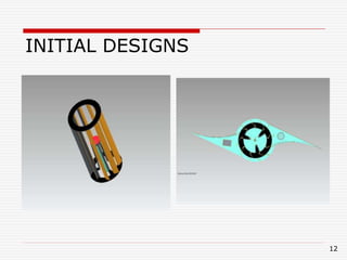
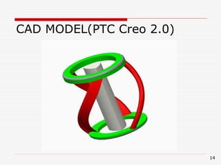


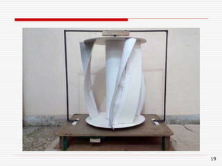
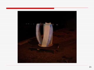

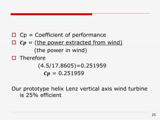


This document summarizes the design and analysis of a vertical axis wind turbine for use on highways in India. It includes the following key points: 1) The motivation was to design a wind turbine that could harness wind energy from passing vehicles to power streetlights along highways, improving nighttime visibility and safety. 2) An initial design was created based on Lenz's vertical axis wind turbine design. It was then modeled, simulated using ANSYS, and a prototype was built for testing. 3) Testing of the prototype found it was able to produce up to 4.5W of power from wind, achieving an efficiency of 25%. Analysis showed with optimized production, efficiencies over 28% could be achieved to