Downloaded 100 times
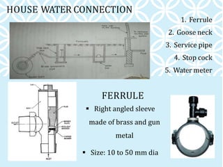
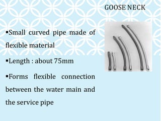
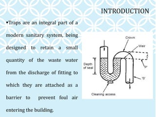
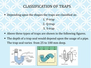
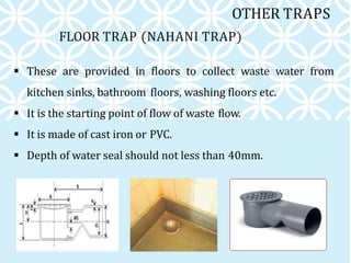


The document discusses various components of household water and drainage systems. It describes the ferrule, goose neck, service pipe, stop cock, and water meter that comprise the water connection to a house. It then explains common drainage system terms like soil pipe, waste pipe, vent pipe, and rainwater pipe. The document outlines sizes for different types of pipes and the objectives of drainage systems. Finally, it discusses different types of traps (P, Q, S traps), floor traps, gully traps, and intercepting traps used in plumbing systems.


