Downloaded 13,361 times


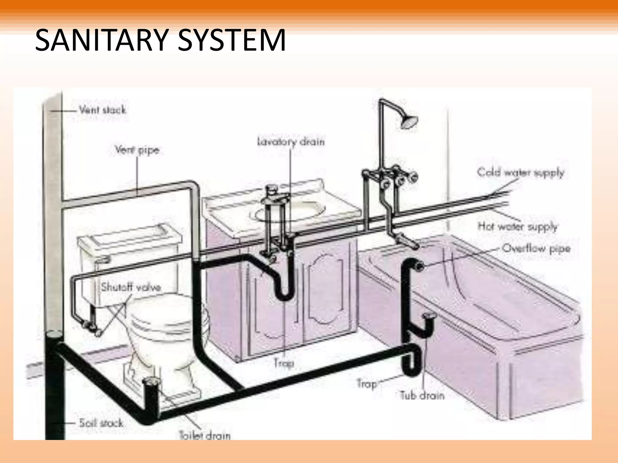


The document discusses water distribution systems and sanitary systems. It describes the main components of water distribution systems including pipes, valves, fittings and motors. It also discusses the components of sanitary systems such as traps, pipes, fittings and different plumbing systems. Plumbing systems discussed include single stack, fully ventilated stack, one pipe and dual pipe systems.